tive was to define the limitations of the web applications in a Peer-to-Peer net- .....
Flash document file. FLV. Flash video files. FMS. Flash Media Server. GPS ......
For example Flash Player version 9 and the newer ones have two separate
Action- ... released in 2010 for Linux based mobile platforms, such as Android 2.0
[46].
DEPARTMENT OF ELECTRICAL AND INFORMATION ENGINEERING DEGREE PROGRAMME IN ELECTRICAL ENGINEERING
PLATFORM INDEPENDENT WEB-BASED PEER-TO-PEER APPLICATION
Author Miika Määttä Supervisor prof. Mika Ylianttila Accepted
Grade
/
2010
Määttä M. (2010) Platform Independent Web-Based Peer-to-Peer Application. Department of Electrical and Information Engineering, University of Oulu, Oulu, Finland. Master’s thesis, 67 p.
ABSTRACT The objective of this thesis was to build a platform independent real-time web application which uses a standard Peer-to-Peer network. In addition, the objective was to define the limitations of the web applications in a Peer-to-Peer network. The contemporary web design techniques enable a fast and easy way of implementing powerful web applications that closely match the usability and performance of a native application. The platform independent nature of the web applications allows an easy way of deploying the applications for a wide device base. Also, the popularity of Peer-to-Peer computing has increased, and therefore the standardization organizations and the information technology industry have started standardizing Peer-to-Peer algorithms and protocols. Because of the increasing popularity of powerful web technologies and Peer-to-Peer networking it is important to study the possibilities of a platform independent web application that uses a standard Peer-to-Peer network. In this thesis, the constructive research method was used to reach the objective. The current Peer-to-Peer solutions are platform dependent and require separate installation from the user. The contribution of this thesis was to develop a platform independent prototype web application that does not require separate installation from the user. The performance of the web application developed in the thesis was compared to the current Peer-to-Peer solutions. In this research, it was found out that it is possible to develop a web application that uses a Peer-to-Peer network. Performance tests, in their turn, showed that the performance of the web technologies is not a bottleneck in Peer-to-Peer networking. However, there are some limitations in the contemporary platform independent web applications compared to the platform dependent applications. Communication between two platform independent applications is not possible. Therefore, a media server is required to handle the real time communication between the users. Due to this communication limitation, the web application cannot provide its own resources to the other users in a Peerto-Peer network. As a consequence, a web application can only act as a client in the Peer-to-Peer network at the moment. Keywords: software development, peer-to-peer networking, web development, Flash.
Määttä M. (2010) Alustariippumaton web-pohjainen vertaisverkkosovellus. Oulun yliopisto, sähkö- ja tietotekniikan osasto. Diplomityö, 67 s.
TIIVISTELMÄ Diplomityön tavoitteena oli rakentaa ohjelmistoalustasta riippumaton reaaliaikainen web-sovellus, joka käyttää standardia vertaisverkkoa. Lisäksi tavoitteena oli selvittää web-sovelluksien puutteita vertaisverkossa. Nykyiset websuunnittelumenetelmät nopeuttavat ja helpottavat tehokkaiden web-sovelluksien tekemistä. Lisäksi nykyisten web-sovellusten käytettävyys ja tehokkuus ovat vertailukelpoisia alustastariippuvien sovellusten kanssa. Koska web-sovellukset ovat alustariippumattomia, niitä voidaan jakaa laajalti. Vertaisverkkojen suosion kasvamisen vuoksi standardisointiorganisaatiot ja teknologiateollisuus ovat aloittaneet vertaisverkkoihin liittyvien osien standardoinnin. Web-teknologian ja vertaisverkkojen suosion vuoksi on tärkeää tutkia Web-sovellusten hyödyntämistä vertaisverkoissa. Diplomityössä käytettiin konstruktiivista tutkimusmetodia. Nykyiset vertaisverkkoa käyttävät ratkaisut ovat alustariippuvia ja käyttäjän on asennettava ne käyttämäänsä laitteeseen. Tämän työn tavoitteena oli kehittää alustariippumaton web-sovellus, jota ei tarvitse erikseen asentaa käytettävään laitteeseen. Tutkimuksessa verrattiin alustariippumattoman websovelluksen suorituskykyä olemassa oleviin vertaisverkkosovelluksiin. Tutkimuksessa havaittiin, että web-sovellus voi käyttää vertaisverkkoa. Suorituskykymittauksessa havaittiin, että web-sovelluksen suorituskyky on riittävä toimimaan vertaisverkossa. Web-sovelluksessa oli kuitenkin puutteita verrattuna aiempiin vertaisverkkosovelluksiin, sillä web-sovellusten välille ei voitu muodostaa suoraa yhteyttä. Sen sijaan sovellusten välinen realiaikainen yhteys voitiin muodostaa palvelimen kautta. Tämän vuoksi nykyisin web-sovellus voi toimia vertaisverkossa vain asiakaskoneena. Avainsanat: ohjelmistokehitys, vertaisverkot, verkko-ohjelmointi, Flash.
TABLE OF CONTENTS ABSTRACT . . . . . . . . . . . . . . . . . . . . . . . . . . . . . . . . . . . . . . . . . . . . . . . . . . . . . . . . . . . . . . . TIIVISTELMÄ . . . . . . . . . . . . . . . . . . . . . . . . . . . . . . . . . . . . . . . . . . . . . . . . . . . . . . . . . . . . . PREFACE . . . . . . . . . . . . . . . . . . . . . . . . . . . . . . . . . . . . . . . . . . . . . . . . . . . . . . . . . . . . . . . . . . ABBREVIATIONS . . . . . . . . . . . . . . . . . . . . . . . . . . . . . . . . . . . . . . . . . . . . . . . . . . . . . . . . . 1. INTRODUCTION . . . . . . . . . . . . . . . . . . . . . . . . . . . . . . . . . . . . . . . . . . . . . . . . . . . . . . 1.1. Research background . . . . . . . . . . . . . . . . . . . . . . . . . . . . . . . . . . . . . . . . . . . 1.2. Research objective . . . . . . . . . . . . . . . . . . . . . . . . . . . . . . . . . . . . . . . . . . . . . . 1.3. Introduction to the research method . . . . . . . . . . . . . . . . . . . . . . . . . . . . . . . 2. RICH INTERNET APPLICATIONS . . . . . . . . . . . . . . . . . . . . . . . . . . . . . . . . . . . . . 2.1. Basics of web . . . . . . . . . . . . . . . . . . . . . . . . . . . . . . . . . . . . . . . . . . . . . . . . . . 2.2. Web application . . . . . . . . . . . . . . . . . . . . . . . . . . . . . . . . . . . . . . . . . . . . . . . . 2.3. Structure of a web application . . . . . . . . . . . . . . . . . . . . . . . . . . . . . . . . . . . . 2.4. Requirements for the contemporary web applications . . . . . . . . . . . . . . . . . 2.5. Characteristics of rich internet systems . . . . . . . . . . . . . . . . . . . . . . . . . . . . . 2.5.1. Characteristics of Rich Internet Applications. . . . . . . . . . . . . . . . . . . . . 2.5.2. Examples of web technologies . . . . . . . . . . . . . . . . . . . . . . . . . . . . . . . . . 3. PEER-TO-PEER NETWORKING . . . . . . . . . . . . . . . . . . . . . . . . . . . . . . . . . . . . . . . 3.1. Definition of Peer-to-Peer . . . . . . . . . . . . . . . . . . . . . . . . . . . . . . . . . . . . . . . . 3.2. Classification of Peer-to-Peer architectures . . . . . . . . . . . . . . . . . . . . . . . . . 3.3. Characteristics of Peer-to-Peer system . . . . . . . . . . . . . . . . . . . . . . . . . . . . . 3.3.1. Degree of centralization . . . . . . . . . . . . . . . . . . . . . . . . . . . . . . . . . . . . . . . 3.3.2. Overlay network structure . . . . . . . . . . . . . . . . . . . . . . . . . . . . . . . . . . . . . 3.3.3. Distributed Hash Table algorithms . . . . . . . . . . . . . . . . . . . . . . . . . . . . . . 3.4. Peer-to-Peer Session Initiation Protocol . . . . . . . . . . . . . . . . . . . . . . . . . . . . 3.4.1. Session Initiation Protocol . . . . . . . . . . . . . . . . . . . . . . . . . . . . . . . . . . . . . 3.4.2. Session Initiation Protocol with Peer-to-Peer networking . . . . . . . . . . 4. DEVELOPMENT OF THE PEER-TO-PEER SOLUTION . . . . . . . . . . . . . . . . . 4.1. Defining the Peer-to-Peer service . . . . . . . . . . . . . . . . . . . . . . . . . . . . . . . . . . 4.2. Technical design . . . . . . . . . . . . . . . . . . . . . . . . . . . . . . . . . . . . . . . . . . . . . . . 4.2.1. Objective of the design . . . . . . . . . . . . . . . . . . . . . . . . . . . . . . . . . . . . . . . . 4.2.2. Development tools and environment . . . . . . . . . . . . . . . . . . . . . . . . . . . . 4.2.3. Technical requirements . . . . . . . . . . . . . . . . . . . . . . . . . . . . . . . . . . . . . . . . 4.2.4. Basic architecture of the system . . . . . . . . . . . . . . . . . . . . . . . . . . . . . . . . 4.3. Implementation . . . . . . . . . . . . . . . . . . . . . . . . . . . . . . . . . . . . . . . . . . . . . . . . 4.3.1. Objective of the implementation . . . . . . . . . . . . . . . . . . . . . . . . . . . . . . . . 4.3.2. Implementation of the application . . . . . . . . . . . . . . . . . . . . . . . . . . . . . . 5. EVALUATION . . . . . . . . . . . . . . . . . . . . . . . . . . . . . . . . . . . . . . . . . . . . . . . . . . . . . . . . . 5.1. Results . . . . . . . . . . . . . . . . . . . . . . . . . . . . . . . . . . . . . . . . . . . . . . . . . . . . . . . 5.1.1. Final application . . . . . . . . . . . . . . . . . . . . . . . . . . . . . . . . . . . . . . . . . . . . . . 5.1.2. Experiments . . . . . . . . . . . . . . . . . . . . . . . . . . . . . . . . . . . . . . . . . . . . . . . . . . 5.2. Discussion . . . . . . . . . . . . . . . . . . . . . . . . . . . . . . . . . . . . . . . . . . . . . . . . . . . . 5.2.1. Web development techniques . . . . . . . . . . . . . . . . . . . . . . . . . . . . . . . . . . . 5.2.2. Feasibility of the architecture . . . . . . . . . . . . . . . . . . . . . . . . . . . . . . . . . . 5.2.3. Functionality of the web application . . . . . . . . . . . . . . . . . . . . . . . . . . . . 6. SUMMARY . . . . . . . . . . . . . . . . . . . . . . . . . . . . . . . . . . . . . . . . . . . . . . . . . . . . . . . . . . .
2 3 6 7 9 9 9 10 11 11 11 12 14 15 15 17 19 19 20 20 20 23 24 25 25 25 27 27 28 28 28 31 32 34 34 35 38 38 38 42 46 46 47 48 50
7. REFERENCES . . . . . . . . . . . . . . . . . . . . . . . . . . . . . . . . . . . . . . . . . . . . . . . . . . . . . . . . 52 8. APPENDICES . . . . . . . . . . . . . . . . . . . . . . . . . . . . . . . . . . . . . . . . . . . . . . . . . . . . . . . . . 56
PREFACE This thesis was done for the DECICOM research project at MediaTeam group at the University of Oulu, Finland. DECICOM (Decentralized Inter-Service Communications) is a three-year project in the area of distributed Peer-to-Peer based services in mobile networks. The purpose of this thesis was to support DECICOM project to achieve its objectives. First, I would like to thank my supervisor Professor Mika Ylianttila. I would also like to thank my advisor M.Sc. Erkki Harjula for his guidance and comments during the research. I also got great help from the Ericsson Nomadiclab personnel; I wish to thank them as well. Most importantly, I would like to thank Tuulia, Saku and Riina for voluntarily helping me to complete this process - I am sure I will reward your work with a great party! April 5, 2010 Miika Määttä
ABBREVIATIONS AAC Ajax AMF API ASP AVM BBB CAN CASE CGI CPU CSS DECICOM DHT FLA FLV FMS GPS GUI HCI HTML HTTP IDE IETF IM IP LGPL LRM MP3 MPEG-4 AVC MPL OBR OOBE OSFlash P2P P2PSIP P2PSIP WG PHP PS RFC RIA RTMFP RTMP S60 SDK
Advanced Audio Coding asynchronous JavaScript and XML Action Message Format Application Interface Active Server Pages ActionScript Virtual Machine Big Blue Button Content Addressable Network Computer-Aided Software Engineering Common Gateway Interface Control Processing Unit Cascading Style Sheets Decentralized Inter-Service Communications Distributed Hash Table Flash document file Flash video files Flash Media Server Global Positioning System Graphical User Interface Human-Computer-Interaction Hypertext Modelling Language Hypertext Transfer Protocol Integrated Development Environment Internet Engineering Taskforce Instant Messaging Internet Protocol Lesser General Public Licence Local Relational Model MPEG-1 Audio Layer 3 Motion Picture Experts Group-4 Advanced Video Coding Mozilla Public License Out-Of-Box Readiness Out-Of-Box Experience Open Source Flash Peer-to-Peer Peer-to-Peer Session Initiation Protocol Peer-to-Peer Session Initiation Protocol Work Group Hypertext Preprocessor Proxy Server Request For Comments Rich Internet Application Real Time Media Flow Protocol Real-Time Messaging Protocol Series 60 Software Development Kit
SIP SMS SWF TCP TEKES TTL UA UAC UAS UI UML VoIP W3C XML XUL
Session Initiation Protocol Short Message Service Shockwave Flash Transmission Control Protocol Finnish Funding Agency for Technology and Innovation Time-To-Live User Agent User Agent Client User Agent Server User Interface Unified Modelling Language Voice Over Internet Protocol World Wide Web Consortium Extensible Markup Language XML User Interface Language
1. INTRODUCTION 1.1. Research background Use of internet has increased remarkably in the last decade. Nowadays, web applications are used in almost every web domain. Current communication and network technologies are changing the way people interact with web applications, providing them powerful mobile communication devices with ubiquitous access to network. Web services and applications must be highly tailored to users’ special requirements. [1] Contemporary design techniques enable a fast and easy way of implementing powerful web applications. Development tools enable implementing of impressive Graphical User Interfaces (GUI) that closely match the usability and performance of a native application. [2] Peer-to-Peer (P2P) based applications have gone through several evolutionary steps since the first file sharing applications. Due to increasing popularity of P2P computing, the standardization organizations as well as the information technology industry have started concentrating on standardizing P2P algorithms and protocols. [3] Recent technological advances in mobile networking and mobile device capabilities have made P2P networking possible in mobile domain as well. Session Initiation Protocol (SIP) is the most important protocol for session management, instant messaging and presence information exchange in mobile networks. Since SIP provides a possibility of connecting a mobile device with any SIP-enabled computer in the internet, it removes barriers between the mobile and fixed networking. The Internet Engineering Task Force (IETF) has formed a work group for researching the possibility of serverless usage of Session Initiation Protocol (SIP). The protocol is called Peer-to-Peer SIP (P2PSIP). [3]
1.2. Research objective The objective of this thesis was to study possibilities of using a standard P2PSIP network with the help of a platform independent web application. Using the web application should require only a web browser and therefore the usage of the application should not require any SW installation from the user. At the same time, the objective was to find possible obstacles preventing contemporary web applications from using the P2PSIP networking. The web application should utilize P2PSIP overlay network so that it is able to connect with peer computers in the network. The web application should also be able to store and retrieve data to the overlay network and to connect with other users. Besides developing a platform independent web application, the objective was to study the performance of the application. Focus was on delays associated with joining and establishing a connection between two users in P2PSIP overlay. The experiments were executed using PlanetLab test network as P2PSIP overlay. These delays were compared to corresponding results measured by Jouni Mäenpää and Gonzalo Camarillo using a prototype application implemented in Java [4] . The same PlanetLab test network was used in Mäenpää’s experiments [4] . Simply put, the research question could be presented as follows: Is it possible to develop a platform independent web
10 application which uses P2PSIP network and if so what are the limitations of the development? The research question proper relates to Decentralized Inter-Service Communications (DECICOM) project. The plan was to develop the web application by means of prototyping the required functionalities. DECICOM project will use the application for demonstration purposes inside the project.
1.3. Introduction to the research method In this thesis, the constructive research method was used, which was a suitable method, because the purpose of this thesis was to develop a P2P application using P2PSIP overlay network. However, the contribution of the solution planned in this thesis compared to old solutions was clear. Old prototype applications were developed as platform dependent and they also required users to install the application in the device. The objective of this thesis was to develop a web application that is platform independent and does not require separate installation from the user. [5] The constructive research means that a solution is built or constructed using existing knowledge in new ways. Constructive research gives a possibility for adding new missing links that are needed to support the whole structure. The construction research is done by designing and developing using tailored building blocks to find the gaps and support the future solution envisaged. For example, algorithms, models, diagrams and software development methods are typical artefacts used for construction in research and engineering. Constructive solutions are usually designed and developed instead of being discovered. [6] The following phases are proposed for the constructive approach: [6] • Find a practical and relevant problem which also has research potential. • Adopt a general and comprehensive understanding of the topic. • Construct and innovate a solution idea. • Demonstrate that the solution is functional. • Show the research contribution and the theoretical connections of the solution. • Examine the applicability of the solution. The scientific validity of the research is based on how well it solves problems or reveals new problems. The criteria for relevant, simple and ease of use are also commonly applied for the functioning application in constructive research. [6] The research starts from Chapter 2, which explains the basics of the web systems and web applications. Chapter 2 also lists the characteristics and requirements of contemporary web applications. Chapter 3 defines the term P2P in a more detailed level and illustrates different types of P2P architectures listed by researchers. Chapter 4 explains the phases of the development. The development tools and selected techniques are reviewed in Chapter 4 as well. Chapter 5 shows the final web application and the results of the performance of the application. Also, the web application development is discussed and analysed in Chapter 5. Chapter 6 summarizes the research.
11
2. RICH INTERNET APPLICATIONS 2.1. Basics of web One of the traditional web architectures is known as a client/server model. A client/server model is illustrated in Figure 1. Clients and servers are connected to each other and in this way they form the web. The connection between the client and the server can be established using for example Transmission Control Protocol (TCP). That is commonly used communication protocol for creating connections and transferring data between computers. [7, 8] If a client wants to receive information from a server, it sends a request into the web in which the servers are listening to the network traffic. Clients and servers use common software rules and protocols, such as Hypertext Transfer Protocol (HTTP), which specify the format of the request. When the server receives the request from the web, it locates the requested information in its local file system, and sends it back to the client computer using TCP connection. [7, 8] Usually, the contents of the web server is called a web page. Most web pages are built using textual documents, such as Hypertext Modelling Language (HTML) or Extensible Markup Language (XML). HTML is used to express the content and the visual formatting of a web page. HTML is a tag language, which means that HTML contains tags that define how text is to be formatted (e.g. font, size and colour) on the display. HTML is a standard managed by World Wide Web Consortium (W3C). HTML is a hypertext language, which means that HTML documents can have links that give the user a way to navigate between the documents of the web system. XML is also a markup language offering web designers another way to express web page content. XML is also managed by W3C. [7, 8]
Figure 1. Basic client/server web system.
2.2. Web application A web application can be defined as an extension on a web system that gives the user a possibility to access business logic with a web browser. According to Conallen, a broad
12 definition of a web application is: "a web application is a web system that allows its users to execute business logic with a web browser." [9] There are several ways to implement a web application which has business logic built in it. For example, instead of requesting the HTML formatted web page from the server’s file system, the client can request the web server to load and run a module. The output of a module can be a formatted HTML page or any other dynamic web content. The original mechanism that allows user input to be processed in a web system is the Common Gateway Interface (CGI). It is a standard interface which allows the user to execute CGI modules (also called CGI scripts) on the server. CGI scripts are usually written in Perl, C or C++ programming language. Most CGI-enabled web server applications require that CGI script must reside in a special directory, from where the client requests it instead of requesting a HTML file. After the requested CGI script is executed on server side, it returns the generated dynamic content to the client. [10] Nowadays, there are more powerful alternatives for interfacing with databases in order to generate dynamic web content (e.g. ASP, PHP and Java servlets), which also are scripting languages. Hence, traditional CGI programming is getting less attention. Figure 2 illustrates basic technologies for generating dynamic web content. [10]
Figure 2. Basic enablers of a web application.
2.3. Structure of a web application Traditional SW application architecture is so called 1-tier architecture, where everything is run on one computer (data storage, business logic, user interface). This does not fill the needs of a web based application which requires a connection between remote computers. Therefore, the application is divided into logical tiers, or chunks, each of which has different roles. [11] A client/server solution shown in Figure 1 is called two-tier architecture, where the first tier is the client and the other one is the server. However, the two-tier solution does not allow to separate modern web applications into several specialized functional layers. The most common approach for today’s web applications is a 3-tier architecture. The 3-tier architecture is illustrated in Figure 3. In the 3-tier architecture, a web
13 browser usually acts as a client, an application server handles the business logic, and the third tier is handling the database functions. [12, 13]
Figure 3. 3-tier architecture of a web system. With most complex web applications, the 3-tier architecture falls short in flexibility and scalability. This happens mainly because of too wide a business logic tier which has too many functions that could be separated into more specialized tiers. Therefore, an n-tier, or a multi-tiered architecture, can provide better structure for complex web applications. The letter "n" means any number of tiers. The biggest advance in the multi-tier approach is that complex business logic can be separated into several functional layers. [13] Figure 4 contains an example of a 5-tier architecture where presentation tier and integration tier are added to simplify the business logic tier. In this example, the presentation tier hides the complexity of the result formatting from the business logic tier. The integration tier handles all the complex communication between the data tier and the business logic tier. The business logic tier needs to make only a simple call to the integration tier to receive the required data. [13]
14
Figure 4. Multi-tier architecture of a web system.
2.4. Requirements for the contemporary web applications Today, web applications are used in almost every web domain. Current communication and network technologies are changing the way people interact with web applications, providing them powerful mobile communication devices with ubiquitous access to network. Services and applications must be highly tailored to users’ special requirements. Hence, for example context-awareness and multichannel access should be taken into consideration in web application design. [1] Here, according to Ceri et al., context is defined as: "any information that can be used to characterize the interaction of a user with a software system (and vice-versa), as well as the environment where such interaction occurs". Mainly, this means that by enhancing the context awareness of web applications, also the usefulness of the application increases since the content provider is able to detect more information of the user’s usage environment, such as the location of the used device or the user. Personalization of web applications has already demonstrated to be beneficial for both users and content providers. [1] Multichannel access to the network is also seen increasingly useful, especially by content providers. Multichannel access means accessing the service from various devices using various web browsers. Communication protocols and mark-up languages make multichannel deployment possible because a totally separated parallel design is not needed to enable presentation in different devices. Hence, it is possible to make multichannel development cost-effectively. [1] Some of the main problems faced by traditional web applications are listed by Joshua Duhl and Preciado et.al: [14, 15] • Process problems: complex web applications require very long HTML pages or that the user must navigate through several pages to complete a single task (e.g. the task of booking a flight)
15 • Data Problems: traditional web applications do not support exploring the data interactively. Usually, the user must find the desired data from the hypertext using input forms. The complexity of the data shown to the user would reduce if some effective data visualization and interactive manipulation would be used. • Configuration problems: often web applications let the user to configure a product or a system, but is unable to present a visual and intuitive picture of custombuild product. (e.g. ordering customized product from a web service). • Feedback Problems: highly interactive web applications must be able to respond to user input and be able to change their state or interface without the need for a full-page refresh or interruptive communications with a server (e.g. games). These capabilities are quite limited with traditional web applications. Common features required from web applications are the following: the presentation capabilities must enable behaviours like drag-and-drop and effective integration of audio and video. Animated vector graphics should be provided to enable a user interface that closely matches native applications. An integrated interaction model between server and client to improve real time communication must be provided. [2]
2.5. Characteristics of rich internet systems 2.5.1. Characteristics of Rich Internet Applications According to Preciado et al., current web, Multimedia and Hypermedia methodologies of web engineering community are incomplete and unable to respond to the new functionalities that users need [15] . Jeremy Allaire from Macromedia introduced the term "Rich Internet Application" (RIA) to overcome the drawbacks of both desktop and web applications. RIAs are proposed as a solution to answer the needs of the users. Normally, RIAs are loaded with some initial data by the client. Then, the RIA can manage data rendering, event processing and communication with the server only when it is required by the application. There are several directions and technologies to extend the interactivity in web applications by running part of the application in the client. According to Bozzon et al., the technologies are classified into four categories: [9] • Scripting-based in which the client side logic is implemented via scripting languages, such as JavaScript, and interfaces are based on a combination of HTML and Cascading Style Sheets (CSS). CSS is used to describe the style of a document written in a markup language, such as HTML. • Plugin-based, where advanced rendering and event processing are granted by browser’s plugins interpreting XML, general-purpose programs or media files (Flash, Flex, Laszlo, Xamlon) • Browser-based, where rich interaction is natively supported by some browsers that interpret declarative interface definition languages. For example XML User Interface Language (XUL).
16 • Web-based desktop technologies in which applications are downloaded from the web but executed outside the browser (Java Web Start, Window Smart Client). Preciado et al. present the general requirements for RIA as listed parameters in Table 2.1. [15]
Interaction Multimedia
Tool CASE Visual Continuity Synchronization
N-Tier development Dynamic data retrieval Parallel requests to different sources Personalization Interactive collaboration
Table 2.1. RIA parameters Possibility to specify the user (active) behaviours Possibility to support the representation of graphics, audio, video, streaming and live multimedia Availability of a Computer-Aided Software Engineering (CASE) tool supporting the methodology Possibility to avoid screen refreshments and blink experiences To provide an active (related with user interaction) and a passive (related with predefined behaviours) representation of interface elements Possibility to provide separate layers for applications Possibility to carry data to/from the server at run time Possibility to retrieve data from one or more simultaneous sources, both in a synchronous and asynchronous way Extensions for internationalization and localization, accessibility, multi-device access, etc. It allows real-time interactive collaboration between different users in order to work together on the same task.
Potential of RIAs comparing to traditional web applications and desktop applications (including client-server capabilities) are presented in Table 2.2. RIA is usually distributed through web and it offers improved interfaces allowing embedding audio, video and other media contents, for example under one plug-in installation (such as Flash Player). RIA also reduces communication overhead by avoiding continuous web page refreshment. Therefore, RIAs can provide better data sorting, filtering, complex visual rendering, etc. [9, 15]
17
Table 2.2. Comparison of Desktop, traditional web applications, and RIAs Feature C/S, Web RIA Desktop Universal client (browser) NO YES YES Client installation Complex Simple Simple Interaction capabilities Rich Limited Rich Server-side business logic YES YES YES Client-side business logic YES Limited YES Full page refresh required NO YES NO Frequent server round-trips NO YES NO Server-to-client communication YES NO YES Disconnected functioning YES NO YES
2.5.2. Examples of web technologies RIA tools There are several different web development techniques that can be used in designing interactive and animated web applications. Most of these techniques consist of some object oriented scripting language and some web modelling language. The following list contains some of the known web technologies: • Curl is for designing interactive web applications. Among other techniques, Curl combines HTML and JavaScript. JavaScript is an object oriented programming language, which is good for creating functionality for the web application. HTML again is easier for designing the layout and the format of the web application. [16] • Ajax is a group of interrelated web development techniques used to create interactivity on web applications. Ajax itself is not a technology at all, but a group of technologies. For example, JavaScript, HTML and XML belong to these technologies. [17] • JavaFX is a software platform, which enables developing rich internet applications. Using JavaFX developers can build and deploy JavaFX applications, which are supported in any computer or device that has Java enabled. JavaFX applications are developed using JavaFX scripting language. [18] • Flash platform is a technology owned by Adobe Systems that is used to create interactivity and animation on web applications. Flash applications are developed combining MXML and ActionScript programming languages. MXML language is a modelling language based on XML. MXML is used to design the layout of the web application. Although functionality can be implemented using MXML as well, ActionScript is more suitable for designing complex functionality. [19] There are a lot of similarities in all technologies mentioned above. The Flash technology will be studied further. Flash was originally introduced by Macromedia, but
18 nowadays it is owned by Adobe Systems Inc. Flash has several features that answer the needs of the users for rich internet applications. Flash combines streaming animation, vector-based graphics, and ActionScript for creating multichannel accessible and interactive content. All Flash content is eventually published to Shockwave Flash (SWF) file which is a repository object that can be presented by the Flash Player. [19, 20] The SWF files can be embedded in a server-side language document, such as HTML [21] . Browsers treat an SWF file as any other embedded object on the web page and displays it by using Flash Player [21] . Besides Adobe, there are also several other entities providing Flash Players for displaying SWF content [22] . Different web applications, like Flash applications, can be developed by using an Integrated Development Environment (IDE) [23] . Software development of applications can be eased by using an IDE which enables the use of different individual tools from one development platform [23] . Adobe Systems provides IDEs, like Flex Builder, for developing Flash applications [21] . Open Source Flash (OSFlash) community has several open source alternatives providing Flash IDEs (e.g. Ajax Animator) [22] .
Media servers and Real-Time Messaging Protocol Media servers are servers that are used in storing media content for internet applications. Media servers are usually open socket servers. The main difference between open socket servers and normal web servers is that as soon as information from a normal web server is received, the connection is closed. Especially with RIAs, it may look like one is still connected to the web server because the data sent from the server might contain animated and interactive content. Actually, the connection is closed right after the web server sends the page with all associated data and one’s computer sends back a response that says the data has received. [24] With an open socket server, the connection stays open until the application terminates the connection. Therefore, audio, video, text, and any other data can be streamed in real time. Real-Time Messaging Protocol (RTMP) has been developed by Adobe Systems for streaming audio, video and other data over the internet between Adobe Flash Platform technologies, such as Flash Player and Flash Media Server (FMS). When using RTMP, the web application first connects to a web server via HTTP and then to a media server using RTMP. Hence, the web application is using simultaneously two different protocols: HTTP for web site and RTMP for streaming media. [24] Adobe has opened the RTMP as an open specification for development communities to create products that enable delivery of Adobe Flash Player compatible audio and video formats [25] . For example, OSFlash community has several different open source Flash projects [22] . Adobe Systems provides a commercial RTMP server called Flash Media Server [24] . OSFlash community has an open source project called Red5, the target of which is to implement an open source RTMP media server written in Java [22] .
19
3. PEER-TO-PEER NETWORKING 3.1. Definition of Peer-to-Peer Peer-to-Peer (P2P) in short means direct connection between two peer computer without a central server or authority. Usually, the terms "node", "peer" or "user" are used to refer to the entities connected in to a P2P network. The most distinctive difference between traditional client/server and P2P architecture is the concept of peers in a network acting as servers and clients. The term servent, which derives from a combination of the terms server and client, is used to describe such an entity. [26, 27] The most important P2P applications that have received considerable research attention are used for content distribution. Typically, content distribution applications allow personal computers to function as distributed storages by contributing digital content to other computers in the network in a coordinated manner. [26, 27] P2P is not only about content distribution and file sharing. P2P architectures are designed for the sharing of distributed computer resources by direct exchange, rather than requiring the intermediation or support of a centralized server or authority. Shared computer resources can be for example content, storage, Control Processing Unit (CPU) cycles or network link capacity. In P2P architecture, the nodes are distributed and are not dependent on each other. Because of the distributed nature of the P2P architecture, the P2P system is able to adapt to failures and accommodate transient populations of nodes while maintaining acceptable connectivity and performance. Examples of such distributed computing systems are Napster, Gnutella, Seti@ sharing Home, OceanStore and many others. [26, 27] The motivation for using P2P architecture in applications derives from their ability to function, scale, and self-organize in the presence of a highly transient population of nodes, network, and computer failures. Also, the P2P system is not dependent on a central server. Therefore, a P2P system overheads its administration much less than traditional web architecture. P2P architectures typically have scalability, resistance to censorship and centralized control, and increased access to resources. Hence, also responsibility of the administration, maintenance and even the ownership of P2P systems are usually distributed among the users, instead of a single company or person. [26, 27] There are several different definitions of P2P, which all usually have quite a lot of similarities. One of the definitions of P2P is proposed by Rüdiger Schollmeier: "A distributed network architecture may be called a Peer-to-Peer (P-to-P, P2P,...) network, if the participants share a part of their own hardware resources (processing power, storage capacity, network link capacity, printers,...). These shared resources are necessary to provide the Service and content offered by the network (e.g. file sharing or shared workspaces for collaboration). They are accessible by other peers directly, without passing intermediary entities. The participants of such a network are thus resource (Service and content) providers as well as resource (Service and content) requesters (Servent-concept)." [26]
20 3.2. Classification of Peer-to-Peer architectures According to Theotokis et al., P2P architectures have been divided into a variety of different application categories listed below: [27] • Communication and Collaboration. Systems that provide the infrastructure for facilitating direct, usually real-time, communication and collaboration between peer computers belong to this category, for example, chat and instant messaging applications such as Chat/Irc, Instant Messaging (Aol, Icq, Yahoo, Msn), and Jabber. • Distributed Computation. This category includes systems that take advantage of the available peer computer processing power (CPU cycles). Computer intensive tasks are divided into smaller work units and distributed to different peer computers. After the corresponding work units are executed in the peer computers, the results are sent back to the peer that originally sent the request. Central coordination is needed for dividing and distributing the tasks and collecting the results. Examples of distributed computation systems are Seti@home, genome@home, and others. • Internet Service Support. Systems in this category are emerged for supporting a variety of internet services. For example, P2P multicast systems, internet indirection infrastructures, and security applications, providing protection against denial of service or virus attacks. • Database Systems. According to the Local Relational Model (LRM), all the data stored in P2P network is assumed to be comprised of inconsistent local relational databases interconnected by sets of “acquaintances” that define translation rules and semantic dependencies between them. Another example of a Database System introduced in Theotokis et al. study is "PIER". It is a scalable distributed query engine built on top of a P2P overlay network topology. It allows relational queries between thousands of computers in overlay network. • Content Distribution. Currently, most of the Peer-to-Peer systems belong to this category. These systems are designed for the sharing of digital media and other data between users. Content distribution systems vary from simple file sharing applications to more complex systems that create a distributed storage medium for secure and efficient publishing, organizing, indexing, searching, updating, and retrieving of data. Some examples of such systems are the late Napster, Publius, Gnutella, Kazaa, Freenet, MojoNation, Oceanstore, PAST, Chord, Scan, FreeHaven, Groove, and Mnemosyne.
3.3. Characteristics of Peer-to-Peer system 3.3.1. Degree of centralization The operation of P2P system relies on a network of peer computers and connection between them. The network lies on top of a physical computer network, which is
21 typically Internet Protocol (IP) network. Therefore, the P2P network is referred as "overlay" network. In the purest, P2P overlay network should be totally decentralized, but in practice this is not always true. Overlay networks are distinguished according to their structure and degree of centralization. These characters affect P2P systems operability since they affect its fault tolerance, self-maintainability, adaptability to failures, performance, scalability and security. [26, 27] P2P systems are divided into subcategories according to the centralization level and structure of the P2P overlay network. According to Rüdiger Schollmeier’s subdefinitions of different P2P systems, they are distinguished between "pure" and "hybrid" P2P networking concepts. In a "pure" P2P system, all the central entities in the network are forbidden and the system must not suffer any loss of network service, whereas a "hybrid" system requires a central entity to provide some parts of the offered network services. [26] A more accurate categorization of P2P overlay network centralization levels is given in Theotokis’ study. He identifies the following three categories. [27]
Purely decentralized architectures This ideal P2P architecture model is completely independent of central coordination since all the nodes, acting as servers and clients (servents), perform all the required tasks in the network. Gnutella is an example of a purely decentralized architecture. Figure 5 illustrates an example of Gnutella network architecture. [27]
Figure 5. Gnutella network architecture. Gnutella builds a virtual overlay network allowing its users to share files with other peers. After joining the network, a node identifies itself with nodes it is connected to. To locate the required file, the servent sends a query to all its neighbours in Gnutella network and each node forwards the query to all neighbours. The response messages are routed back along the opposite path. To reduce the spread of messages through the network, each message contains a Time-To-Live (TTL) information. After every forward, the TTL value is decremented, and when it reaches zero, the message is dropped. When the target file has been identified at a certain node, the node that sent the request initiates a download by establishing a direct connection between itself and the node containing the data. [27, 28]
22 Partially centralized architectures The basic idea of the systems in Partially Centralized Architectures category is similar to the one in purely decentralized architectures. However, some of the nodes, termed as super peers, have a more important role than other peers. Supernodes are acting as local central indexes for files shared by local peers. However, the operability of the network must not rely on a single supernode. Therefore, network must be able to assign new supernode dynamically if one supernode fails to achieve the task it is working on. The way how supernodes are assigned varies between different P2P systems. One example of partially centralized architecture is Kazaa. [27, 29] Main advantages of partially centralized systems in comparison to purely decentralized are that discovery time is reduced and most of the workload can be handled by the supernodes, whereas nodes with less CPU power, bandwidth or storage capabilities have less workload. Figure 6 illustrates an example of partially centralized architecture. [27, 29]
Figure 6. Partially centralized network architecture.
Hybrid decentralized architectures Systems in the Hybrid Decentralized Architectures category have a central server facilitating the interaction between peers. A central server maintains directories of metadata, which contain information about the shared files stored by each peer. Hence, the central server is a single point of failure and the system is vulnerable to censorship, technical failure, or malicious attack. However, peer nodes are in direct interaction between each other when exchanging files, for instance. The central server performs the lookups and identification of the nodes storing the required resources. Therefore, locating the required resource is fast and efficient. [27] Figure 7 highlights the architecture of a typical hybrid decentralized P2P system. Every client computer stores the content shared with the rest of the network. Each client connects to a central directory server. The central directory maintains the re-
23 quired information of each user of the network and the information of the content users are storing. The client requests certain files from the central server, which responds with a list of peers storing the requested content. Then, the client opens a connection between one or more peers holding the requested content and downloads it. Napster is an example of a hybrid decentralized architecture. [27]
Figure 7. Hybrid decentralized network architecture.
3.3.2. Overlay network structure Structure of the overlay network reveals whether it is created non-deterministically as nodes and content are added or whether its creation is based on specific rules. Therefore, networks are categorized in terms of their structure as unstructured and structured networks. [27] In unstructured P2P networks, the placement of the content is completely unrelated to the overlay topology and the content typically needs to be located. There are different search mechanisms, ranging from brute force methods to more sophisticated and resource-preserving strategies. In brute force methods, the content is located propagating queries randomly to the peers in the network until the correct content is found. In more sophisticated search methods, the search mechanism selects to which neighbours the queries are forwarded based on some logic. Unstructured systems are usually more appropriate for accommodating highly-transient node populations. Examples of unstructured systems are Napster, Publius, Gnutella, Kazaa, Edutella and FreeHaven. [27] Structured systems have emerged mainly in an attempt to improve the scalability issues that unstructured systems were originally faced with. Structured networks have tightly controlled overlay topologies and files (or pointers to them) are placed at precisely specified locations. Structured systems provide a mapping between content (e.g. file identifier) and location (e.g. node address), in the form of a distributed routing table to route queries efficiently to the nodes with the desired content. [27]
24 A disadvantage of structured systems is that it is difficult to maintain the structure required for efficiently route messages in a very transient node population, where nodes are joining and leaving at a high rate. Examples of structured systems in Theotokis et al. study are for example Chord, CAN, PAST and Tapestry. Chord, CAN, PAST and Tapestry are also the names used for the lookup algorithms for finding the nodes in a structured systems. The term "loosely structured systems" is used for the systems that are a combination of structured and unstructured systems. [27]
3.3.3. Distributed Hash Table algorithms Structured P2P systems without any centralized servers or hierarchy require some kind of mechanism for controlling content placement and routing. Several research groups have presented a simple and general interface, a Distributed Hash Table (DHT). Data items are inserted in a DHT and found by defining a unique key for that data. To implement DHT, the underlying algorithm must recognize which peer is responsible for storing the data for a corresponding key. Therefore, each peer maintains contact information of a small number of peers ("neighbours") in a routing table. Such peers form an overlay network. Messages to store and retrieve keys are routed between peers in overlay network. [30] A DHT implements only one operation: lookup(key) returns the identity (e.g. IP address) of the node currently responsible for a given key. Basically, the main requirements are that data can be identified using unique numeric keys, and that users are willing to store keys for each other. A simple distributed storage application could use this interface as follows: the user who publishes a file under a particular unique name converts the name to a numeric key using some hash function, then calls lookup(key) and sends the file to the resulting node. Someone who wants to read the file, converts the name to a key, calls lookup(key), and requests the resulting node for a copy of the file. [30] There are substantial differences between the ways DHT algorithms build and maintain their routing tables as nodes join and leave. Examples of DHT technologies used in Peer-to-Peer networking are CAN, Chord, Pastry and Tapestry. The following issues must be addressed when implementing DTH-algorithm: [30] • Keys must be mapped to nodes in a load-balanced way. Basically, all algorithms do this in the same way. Nodes and keys are mapped using a hash function into a string of digits. Hashing the key to a given digit string is then assigned to the node with the “closest” digit string in question (e.g. the one that is the closest numeric successor to s, or the one with the longest matching prefix). • Any node that receives a query for a key identifier X must be able to forward it to a node whose ID is closer to X. To do this, each node maintains a routing table with entries for a small number of other nodes. This method guaranties that eventually the request arrives at the closest node. There are differences in the ways the forwarding is made between different algorithms.
25 • As mentioned above, to forward lookup messages, each node must build and maintain a routing table containing identifiers of some other nodes selected by a mechanism defined by the corresponding DHT algorithm.
3.4. Peer-to-Peer Session Initiation Protocol 3.4.1. Session Initiation Protocol Session Initiation Protocol (SIP) is an application-layer signalling protocol for controlling, creating, modifying, and terminating sessions with one or more participants. These sessions can be for example internet telephone calls, multimedia distribution, or multimedia conferences. SIP is standardized by Internet Engineering Task Force (IETF). [31] SIP sessions between users are created by sending invitations that carry description of the session. SIP uses elements called proxy servers (also called SIP proxy) to route requests to the user’s current location. SIP proxy also provides functionality, such as registration, authentication and authorization of the users for the services. SIP is designed to be independent of the underlying transport protocol layer. [31] Typical elements of the SIP network are SIP User Agent (UA), SIP Proxy Server (PS), SIP Registrar server, and SIP Redirect server. These are described below with more details: [32, 33] • SIP UAs are the applications that react to one another. When a dialog is established, UAs communicate with other UAs. It can reside in the user’s computer or in a server. There are two separate parts in UA, User Agent Server (UAS) and User Agent Client (UAC), both providing different functions. UAC is the originator of the SIP sessions. It establishes a dialogue and maintains that dialogue with the destination user agent. UAS is the recipient of the request made by UAC. UAS responds to requests from UACs. • SIP PS is one of the main elements in SIP network. It is responsible for forwarding the SIP requests to the target UAS or another proxy on behalf of the UAC. Proxy provides the routing function in SIP network. • SIP Registrar server authenticates and records the current location of the UA. The device where UA is locating sends its new location information to the SIP registrar when the location is changed. The location information is saved to location database or location server. • SIP Redirect server is used to provide an alternative address for a SIP request. The reason why alternative address is needed might be for example load balancing between the proxies routing the requests.
3.4.2. Session Initiation Protocol with Peer-to-Peer networking Recently, using Session Initiation Protocol (SIP) in serverless environment has received a lot of attention in research communities and technology industry. [3] IETF
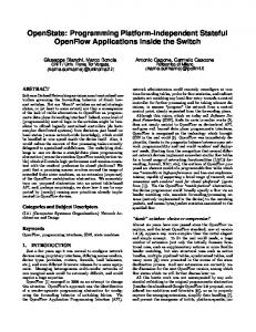
26 has established a working group called Peer-to-Peer Session Initiation Protocol Work Group (P2PSIP WG). The target of the P2PSIP WG is to develop protocols and mechanisms for the use of the SIP in environments where the service of establishing and managing sessions is principally handled by a collection of intelligent endpoints, rather than centralized servers as in SIP as currently deployed. [34] The Peer-to-Peer overlay would consist of P2PSIP peers and P2PSIP clients. P2PSIP clients would act very much like SIP UAs. P2PSIP peers would act as super nodes. The super node, similar to the SIP registrar and proxy server, locates other users by communicating with other super-nodes. The idea is that the node which has enough capacity can become a super node. Figure 8 illustrates the difference between traditional client/server SIP and P2PSIP network architectures. (Figure 8a). Figure 8b presents a P2PSIP network architecture where the traditional SIP network is transferred more into a P2P networking-like architecture. [35]
(a)
(b)
Figure 8. (a) Traditional client/server SIP network architecture. (b) P2PSIP network architecture.
27
4. DEVELOPMENT OF THE PEER-TO-PEER SOLUTION 4.1. Defining the Peer-to-Peer service The objective of this thesis was to implement a platform independent web application which uses standard P2PSIP network. It would be the first platform independent prototype application using the standard P2PSIP overlay network. Another objective of the design of the web application was that it does not require any separate installation activities from the user. The web application was needed for demonstration purposes in the Decentralized Inter-Service Communications (DECICOM) project. [36] DECICOM focuses on the research and development of technology enablers for distributed mobile applications and services, and the new business scenarios around them. DECICOM provides a communication framework for P2P and hybrid P2PClient/Server communication systems. The project aims to influence global standardization of the essential enabling technologies for P2P systems in a concrete manner. [37] MediaTeam from the University of Oulu and Networking Laboratory from the Helsinki University of Technology are the research partners of the DECICOM project [37] . Industrial and financing partners of the DECICOM are: Nokia Research Center, L M Ericsson, Nethawk, Futurice, Icecom and TEKES. This study was assigned and implemented in co-operation with MediaTeam Oulu and L M Ericsson. [36] Among other studies, the DECICOM project has developed several prototypes of P2P applications. Most of them are mobile P2P solutions developed for Symbian based S60 or Linux based Maemo application platforms. The earlier studies have proved the functionality of the P2P networking. However, they are not using the standard P2PSIP overlay network. [37] The earlier prototypes were also developed to support only a specific operating system or an application platform as native applications [37] . Every time such a solution is ported on a different application platform or an operating system, new development efforts are required. One of the targets of the RIAs is multichannel accessibility. The users with ubiquitous access to network use web services with various devices and various operating systems. With existing solutions, for example, a prototype implemented for Symbian S60 mobile phone cannot be used by a user with a desktop computer that has Windows operating system. [38] Users face practical problems when they start using a new system or service. Novice usage is an important and growing theme in Human-Computer-Interaction (HCI). Especially in the last decade since home has increasingly become as a networked entity with various connected devices and services. Therefore, Out-Of-Box Readiness (OBR) is another important goal to achieve in the design of the web service. The term OBR is used by a manufacturer to develop as good Out-Of-Box Experience (OOBE) for the user as possible. OOBE means how the user experiences a new product, in this case, a web application. [39] The operating system dependent native P2P application prototypes developed earlier by DECICOM project must be installed separately by the user. That was seen as a weak point since it degrades the OOBE of the service by making the mobilization of the service more difficult [40] .
28 4.2. Technical design 4.2.1. Objective of the design The kick-off meeting for the development part of the thesis was arranged between L M Ericsson and MediaTeam Oulu. In that meeting, it was agreed to develop an application running on top of a web browser that uses a P2PSIP overlay network. The main options for the technology platform to be used in the development were Ajax (JavaScript based) and Flash (ActionScript based). The web browser plugin based Flash technology was agreed to be used to develop the solution. The main reason for this was that the Flash supports TCP socket connection, whereas the Ajax does not. The basic technical functionalities that the prototype web application must be able to use, when interacting with the P2PSIP overlay, are storing and retrieving data from the overlay and an ability to connect to a peer in the overlay. Connection to peers in the overlay is made using TCP socket connection. The basic technical functionalities required from the overlay are listed above. The plan was that the prototype web application uses the P2PSIP overlay through the P2PSIP Application Interface (API). L M Ericsson was responsible for implementing the P2PSIP API, which provides the basic functionality to communicate with the standard P2PSIP overlay network. It was agreed that the prototype web application should enable VoIP (Voice over Internet Protocol) and basic Instant Messaging (IM) functionality between users. Practically IM means chat.
4.2.2. Development tools and environment Flash The Flash technology was selected as the technology to develop the web application for this project. The main reason for this was that Flash is considered as the most popular technology in web application development. Therefore, it was known that the number of the Flash developers is high. [20] Also, unlike Ajax, Flash platform supports TCP socket connection, which was needed to get the application use the standard P2PSIP overlay network. [17] What is more, animated graphical examples of Flash applications could be found from several web domains. In prototyping phase, it was easily proven that, with Flash technology, the basic use cases, such as VoIP and IM, were straight forward to implement. [19] Adobe Flex 3 is a Software Development Kit (SDK) for development and deployment of Flash rich internet applications. [20] Flex 3 SDK is released under the open source Mozilla Public License (MPL) [41] . Flex Builder 3 is an IDE which enables visual design of Flash applications. Flex Builder 3 requires a license from Adobe Systems. Current Flash applications are coded using MXML and ActionScript 3.0 programming languages. Such applications are also called as Flex applications. MXML is an XML based declarative markup language and it is used to display the layout of the Flex applications. Also interactivity and functionality can be developed using MXML language, although most of the interactivity is usually developed using ActionScript. [19]
29 ActionScript 3.0 is an object oriented programming language for creating applications. However, ActionScript and MXML languages are combined in Flex and both of them have their benefits. MXML is easier for designing layout, while ActionScript is better for designing business logic. All MXML code is converted as ActionScript code in compilation. MXML documents are essentially ActionScript classes. ActionScript applications are compiled and built to a Shockwave Flash (SWF) files. A SWF file can contain animated vector graphics and functionality. [42] SWF files are also called as Flash movie files and they can be replayed by the Flash Player. It is also possible to add video in SWF files. The format of the Flash video files is FLV. An FLV file must be imported to a Flash document file, which will be called as an FLA file. They all are published as SWF files. However, there is also an option to replay an external video from Flash application. This is an advantage, since embedding the video in the SWF file significantly increases the size of the file. The FLV or H.264 video container file can be loaded by the SWF file at runtime. That happens for example when the web page loads or playback is separately initialized by ActionScript command from the web application. [43] H.264 is also a standard for the coded representation of visual information. H.264 is also known as MPEG-4 AVC format. [44] The Flash Player is a browser plugin, which can replay SWF files from web sites. It means that Flash Player executes the Flash application and displays and renders the visual and interactive content. The Flash Player supports the majority of operating systems and browsers. There is also Flash Lite player for mobile phones. However, it is important to notice that all the Flash applications cannot be replayed with every Flash Player. [19] For example Flash Player version 9 and the newer ones have two separate ActionScript Virtual Machines (AVM1 and AVM2). AVMs execute technically the Flash applications. Dual AVM architecture is designed to support Flash applications implemented for old versions of Flash Player. AVM1 executes Flash applications designed for older Flash Players. AVM2 is designed fundamentally in a different way than AVM1 and it executes the Flash applications made for newer versions of Flash Player. Older versions of Flash Players have only AVM1. Therefore, Flash applications that are designed for the latest Flash Players cannot be executed in old Flash Players. [19] The latest version of the Flash Player is version 10. All Flash applications designed for Flash Player 10 do not work in Flash Player 9 if new functionality designed for version 10 is used. However, Adobe estimates that each new version of the Flash Player has been adopted in more than 80 percent of the computers in less than a year after publishing. [20] Compatibility is still a problem in devices that do not support the latest version of the Flash Player, for example in mobile devices. New Flash applications developed in ActionScript 3 are not supported by the Flash Lite player. Also, the latest Linux based mobile devices like Nokia N900 (built on top of Maemo5) supports only Flash Player 9 [45] . Although, according to news in tech forums, Flash Player 10 should be released in 2010 for Linux based mobile platforms, such as Android 2.0 [46] . Real-Time Messaging Protocol (RTMP) supports real time communication between different Flash platform technologies. However, currently it does not support direct connection between two Flash Player applications. Adobe has published a project called Stratus which should support sending real time data from a Flash client to
30 another. Stratus project is still in beta phase and supported only in Flash Player 10. It also requires Adobe Flash Media Server (FMS) to work. [20] It was decided not to use the Stratus in this thesis. Therefore, an RTMP supported server is needed for handling the real time communication between the web applications. [19]
Media server Red5 media server was considered as the best option for handling the media server activities for the web application in this thesis. Red5 is an open source Flash server implemented in Java. Red5 supports open socket connection and RTMP protocol. Therefore, a continuous connection between the client and the server can be maintained, which enables real time communication. Red5 open source project is hosted by Open Source Flash (OSFlash). OSFlash is an open source community hosting open source projects for the Flash platform. [22] Red5 uses Lesser General Public License (LGPL) [47] . Among other features, Red5 supports features listed below: [22] • Streaming audio and video (FLV, H.264, AAC, and MP3). The Red5 Flash server can stream audio and video coming in and going out from the server. • Recording client streams (FLV). This means that the Red5 Flash server can store incoming FLV video stream. • Shared objects. Shared objects can store data on the Red5 Flash server for other clients to retrieve. The remote shared objects are stored in the Red5 server. Whenever a client makes changes to the shared object, the change is visible for other clients as well. It is possible to share data, such as IM, in real time using remote shared objects. To use remote shared objects, the user must be connected to the media server with the RTMP protocol. • Live stream publishing. The Red5 Flash server is able to broadcast audio or video stream in real time for Flash clients. • Remoting between a Flash client and the Red5 Flash server. The data exchange between the two entities must be done in Action Message Format (AMF). There are different versions of the AMF. The AMF 3 version is used with ActionScript 3.0 and that is also supported in new versions of Red5 Flash server. • Real-Time Messaging Protocol (RTMP). The RTMP is introduced by Adobe Systems and is used for real time communication between different Flash platform technologies, such as Flash Player and Red5 Flash server. Also Adobe FMS supports RTMP and all the features in the web application should be feasible to implement using FMS. Adobe FMS requires a license and Red5 is an open source project. [24] Therefore, the main reason to select the Red5 server to be used in this thesis was that the chargeable license was not needed. [22]
31 4.2.3. Technical requirements A more detailed way of making the VoIP and IM features for the web application was defined after a short study of existing Flash solutions that used some media server for connecting two Flash clients. At least one example of a basic VoIP Flash application hosted in Google Code community was found. The application was called Red5Phone. Red5Phone enabled basic voice calls between two Flash clients using SIP connection. [48] Red5Phone is built on top of the Red5 server. The downside of the Red5Phone is that it requires implementation of a web application residing on the Red5 server. The application includes Flash part and SIP part. SIP part is needed to enable SIP connection between UAC and SIP proxy. The SIP part of the application is implemented in Java as a server side web application. Red5Phone Flash part used ActionScript functionality to call methods in Java implemented SIP part. In the design of the P2P system of this thesis, it was already known that the Red5 media server was required for connecting the Flash clients. However, we did not want the Red5 server to contain a server side web application or business logic. Therefore, the Red5Phone concept as such was not sufficient for this project. Figure 9 illustrates the architecture of the Red5Phone. Another example using Red5 server was Big Blue Button (BBB), which have much more functionality implemented than in Red5Phone. But the basic architecture is similar to the one in Red5Phone and it also requires an extensions on top of the Red5 server. [48, 49]
Figure 9. Red5phone architecture. However, it was noticed that opening a plain RTMP connection between two Flash web applications also required a minimum web application on the Red5 server side. Unlike Red5Phone solution, the minimum server side web application did not require implementation of logic residing on the server. The server still must contain the basic configuration files that allow the Flash web application to connect to the Red5 server. Red5 stores all web application definitions as folders inside the “webapps” directory.
32 In order to create a new application, a new subfolder must be created beneath “webapps”. This folder should get the same name as the web application connecting to the server. A “WEB-INF” folder must be created inside the new web application folder. Red5 documentation includes templates about the basic configuration files that must exist in the "WEB-INF" folder. [22] To enable RTMP connection between Flash clients, the contents of the configuration files could be minimal. The following basic configuration files can be found from each Red5 server side web application: [22] • web.xml. The main configuration file of the Red5 web application. To ensure that Flash web applications are able to make RTMP connection to the Red5 web application, only the "WebAppRootKey" parameter is required. Basically, that is a unique name of the web application. • red5-web.xml. This is a Handler Configuration file. It defines the services and handlers the web application is using. • red5-web.properties. This file defines properties and is a configuration file for red5-web.xml. After the Red5 server has been installed and the basic server side web application defined with required configuration data, it is possible to create an RTMP connection between Flash web application and Red5 server. With an RTMP connection to the Red5 server, a Flash web application can create remote shared objects. A shared object can store data on the server for other Flash clients to retrieve. The remote shared object can be for example a plain text field, which is used as an IM chat text field. When one user changes the chat text, it is updated for all the users connected to the object in question. Another important feature for the prototype Flash application was streaming audio. After RTMP connection is established with the client and the server, the NetStream Class enables streaming real time audio through the Red5 server. [50] The connection between the Flash client and the P2PSIP overlay network is established using TCP socket connection. Socket class enables ActionScript to make socket connections and to read and write raw binary data. P2PSIP API creates the connection and handling of the communication between Flash application and peers in the P2PSIP overlay. [50]
4.2.4. Basic architecture of the system After studying the technical capabilities of the Flash technology platform and Red5 server, the high level architecture of the P2P system was defined. The functionalities required by the system were prototyped and proven doable. Figure 10 illustrates the high level system architecture.
33
Figure 10. High level system architecture. As described in Figure 10, the clients may vary from a PC computer to a Flash Player supported mobile device. The basic idea is that the Flash application (the SWF file) resides in a HTTP server and can be connected by any device containing a web browser. The SWF file is downloaded by the web browser and replayed by the Flash Player (1.). Then, the Flash application and the logic behind that are executed locally by the user and the network traffic is minimized, which is one of the basic ideas of RIAs. When logging in the service, Flash application establishes TCP socket connection to a peer in the P2PPSIP overlay network using P2PSIP API (2.). When connection is established, the Flash application can store and retrieve data from the overlay network (3.). Key/value pairs are used to store data in the overlay network. As it was agreed, the communication between Flash applications will happen through the RTMP supported Red5 servers. Therefore, the Flash application must open an RTMP connection with an available Red5 server as well (4.). At its simplest, the overlay network contains the list of available Red5 servers. When the client connects to the overlay, it can request for a free Red5 server address 3.) and connect to it. The overlay network also stores the information about which Red5 server each user is connected to. Hence, when the user A wants to connect with user B, user A can ask if user B is connected or not and what Red5 server user B is using (3.). After that user A can establish an RTMP connection to the same Red5 server as user B and open a real time communication channel between two users (5.). As described in the fiugre 10, Red5 server can be installed to a peer computer or some other computer outside the overlay network. Any peer computer might act as a client and peer. Naturally, the devices in the overlay network must contain the P2PSIP peer capabilities, such as DHT algorithm
34 and capability to maintain data stored to the overlay network. Therefore, acting as a peer requires installation of additional SW to the computer.
4.3. Implementation 4.3.1. Objective of the implementation More specific functional requirements for the web application were defined according to the high level architecture defined in the design phase. Regarding high level design and prototyping using Flash applications and Red5 Flash server, it was proved that the desired system should be possible to implement. The definition of the P2PSIP API was started at the same time as developing the Flash web application. The main part of the Flash application development was made with the P2PSIP API emulator, which was called the dummy P2PSIP API. The actual overlay network did not exist, but the emulator simulated the operations of the overlay network. Therefore, it was known that the first definitions of the API might change as the development work proceeds. The list of functional requirements from the user perspective was defined more accurately before starting the actual implementation. A classification was given to each high level requirement according to the importance of each requirement. The classifications were used as defined by the IETF Request For Comments (RFC) document 2119. Capital letters are used in classification keywords to distinguish them from other text. In short, "MUST" classification for a requirement means that it is absolute and must be fulfilled. "MAY" stands for "optional", meaning that the requirement is truly optional. The high level functionality requirements are listed in Table 4.3. [51]
# 1 2 3 4 5
Table 4.3. Functional requirements of the Flash application Requirement Level Intuitive and animated GUI MUST VoIP call between Flash clients MUST Instant Messaging (IM) functionality between Flash clients MUST Shared calendar MAY File sharing MAY
It was expected that the P2PSIP API will probably not stay unchanged. Also the functional requirements listed in Table 4.3 were defined only in a high level before starting the implementation. The definition of the UI was done during the implementation work too. Hence, agility was required from the way of working and the development tools used in this thesis. Those issues were taken into account when the technology and the tools were selected. In addition, the high level system architecture was designed to be quite flexible to allow changes in the implementation.
35 4.3.2. Implementation of the application Overview The UI flow of the web application was constructed using Flex Builder 3. Flex Builder has a powerful GUI design tool, which generates the MXML code automatically. Hence, customizing the GUI and making changes during the development was easy. A screenshot of the GUI design tool is illustrated in Figure 11.
Figure 11. Flex Builder 3 GUI design tool. The Unified Modelling Language (UML) was used to describe the functionality of the application. UML is a modelling language that is used to specify and visualize software systems. [52] The final UI flow of the application is described in the UML state diagram in Appendix 1. The UI consists of only two main UI components: the "main view" and the "communication view". From the "main view", the user can arrange contacts and start the "communication view" with a desired contact. From the communication view, the user can chat and call her friends. Functionality of the GUI can be seen more accurately from the screenshots in Chapter 5.
36 Used classes The UML class diagram of the application can be seen from Appendix 2. The functionality of the application consists of three main parts: RTMPchat main application, ChatMngr and VoipMngr classes. The P2PSIPClient class is the interface between the GUI part of the application and the P2PSIP overlay network. The interface is also called as P2PSIP API in this thesis. The RTMPchat class includes all the methods controlling the UI of the application. The interactive UI components, for example buttons implemented in MXML, call the ActionScript methods. The methods are listed in the class diagram (Appendix 2). The objects of other three classes are introduced in the main application and instances of those are created to enable communication with the other users. As mentioned above, the P2PSIPClient class is the interface between the main application and the P2PSIP overlay. The user can request the information of the other users through the P2PSIPClient class. This application stores the online statuses and the Red5 server addresses to the overlay. Also, the list of all the users of the service and the personal contacts of each user are stored to the overlay network. Mainly the get and put functions of the P2PSIP API are used in this application. Get is used to retrieve data from the overlay network. Default responsehandler function is called as a callback function for each get, unless the developer defines a specific responsehandler function. The specific responsehandler function can be defined in each get request separately. The responsehandler function is called after the request is handled. The responsehandler function receives the requested key and corresponding value as parameters. Put function is used to store data to the overlay network. A more accurate description of the public functions of the P2PSIP API is given in Appendix 3. After receiving contact information from the overlay through the P2PSIPClient responsehandler functions, the user can communicate with the other users using ChatMngr and VoipMngr classes. The real time communication is done using RTMP connection through the Red5 server. Classes use remote shared objects residing in the Red5 server and audio streams through the Red5 server to communicate with each other.
Sequence diagrams Intercommunication between classes is described in the UML sequence diagrams in Appendices 4- 9. All needed operations to understand the functionality of the application are shown in those sequence diagrams. The first sequence diagram in Appendix 4 illustrates the login process, which establishes the required connections, which are the TCP socket connection to the P2PSIP overlay and the RTMP connection to the available Red5 server. The shared objects to enable the real time communication between users are also created. The event listeners are initialized to react in case another user contacts using chat or VoIP. After login process, the application is ready to communicate with the other users and is shown as "online" user. Maintaining the lists of the other users is shown in Appendix 5. A list of all users and a list of personal friends of each user are maintained in the P2PSIP overlay. The application updates both lists when the user changes the personal contact list. The ap-
37 plication also synchronizes the list of users in every ten seconds and after a successful login. Appendix 6 shows how the user is kept logged in. The Put function of the P2PSIP API gives a possibility to define a Time-To-Live (TTL) parameter for the key/value pair stored to the overlay. User information is stored to the overlay using the username as a key and used Red5 server address as a value. When the user logs out from the service, the username key is removed from the overlay. However, if the user closes the web browser before logging out properly, the stored username key is not removed from the overlay. Therefore, a TTL value is given as a parameter when the username is stored to the overlay using the put function. The keepLoggedIn timer mentioned in Appendix 6 makes sure that the username key is stored to the overlay every time before the TTL goes off. If the user closes the browser or for example the network connection is lost suddenly, after the TTL period, the user is shown offline for the other users. Appendix 7 illustrates the situation when the user opens a communication with a friend who is online. First, the application asks the address of the Red5 server the friend is using. After that, the availabilityCheck function is used to check that the user is not communicating with someone else. If the user is available, the caller connects to the callee’s shared object and sets the friend and herself busy. IM communication happens using the remote shared object as a text field which is visible for both users. As shown earlier in UML state diagram in Appendix 1, a VoIP call can be established only from the communication window. Therefore, the chat connection is already open before making a call. Making a call to a friend is described in Appendix 8. A VoIP call is also started by checking if the user is available and not connected to someone else. Checking of the VoIP availability is done separately from IM availability to enable the possibility that the user can chat to one friend and call to another simultaneously. However, this is not made possible in the UI design of this application. After noticing that the callee is available, the incoming and outgoing audio streams are created by the caller. If the callee accepts the call, then the callee’s corresponding audio streams are created and both users start to replay each others’ audio streams. Appendix 9 correspondingly shows establishing the VoIP connection from the callee’s point of view.
Integration and verification As mentioned above, the main part of the development of the web application was made with the dummy version of the P2PSIP API. It meant that the actual P2PSIP overlay did not exist and the API used an emulator script that simulated the P2PSIP overlay. After the P2PSIP overlay network part was implemented, the Flash application was integrated with the actual P2PSIP API, which also used the actual overlay network instead of an emulator. The full functionality and more complex use cases were tested after the actual P2PSIP API and the overlay network were up and running. Some minor issues were found, but most of the functionality implemented against the API using the emulator script was working as expected. The list of the test cases for verifying the basic functionality are listed in Appendix 10.
38
5. EVALUATION The objective of this thesis was to find out possibilities of using P2PSIP overlay functionality with a platform independent web application. The results of this constructive research are presented in section 5.1. The results include the functionality and the applicability of the solution. The UI of the final application is presented and the usage of the application is described in section 5.1.1. The feasibility of the solution is studied mainly by comparing the performance of the P2P system in this thesis to existing P2PSIP solutions. These feasibility experiments are described in detail in section 5.1.2. Conclusions and the future work of this thesis are discussed in section 5.2. Section 5.2.1 concentrates on the benefits of web development techniques. The feasibility of the architecture proposed in this thesis for P2P usage is discussed in section 5.2.2. Section 5.2.3 concentrates on the functionality of the web application.
5.1. Results 5.1.1. Final application Figure 12 shows the idle state of the web application after logging in. Friends can be removed from the personal contact list by selecting a friend’s name and pressing the "Remove" button. User can also contact friends from this view by selecting a friend and pressing the "Contact" button.
Figure 12. Idle state after logging in to the web application. After selecting "all users" tab, the state is changed to an all users view, as shown in Figure 13. The user can select one of the friends from the list and press "add" button
39 to add a contact to the personal friends list. After pressing "add" button, the view is changed back to the personal friends view.
Figure 13. All users view of the web application. By pressing "Hide Contacts" button, the contact list is hidden. In the view in Figure 14 the user can press "Show Contacts" button and then the contacts window is brought back. When minimizing the application by hiding the contacts window, the application is shown as a compact panel taking only a little space from the display.
Figure 14. Contact list of the web application is hidden. Error notifications of the actions that are not allowed are given as pop up windows. Pop up windows contain a description of the problem occurred. The communication window pops up when someone starts communicating with the user. In Figure 15, a friend is calling the user. The user can press the "Answer" button to start the VoIP connection or reject the call by pressing the "Reject" button. Both users can also chat to each other when the communication window is open. If the call is rejected or cancelled, the communication window still remains open and the users can chat. But if either of the users presses the close button, the communication window is closed and both of the users are available for other users to contact. In case someone tries to contact a friend who is in communication with someone else, a pop up window is opened notifying that the user is busy.
40
Figure 15. Incoming call from a friend. The communication view of the web application is always the same, no matter if the user is on the starting or receiving side of the communication. The user is contacting one of her friends in Figure 16. As can be seen, the communication window is similar to the one in incoming call in Figure 15. Only the animations and the texts are different, describing what is happening. The user can make a VoIP call from the communication window by pressing the "Call" button. After making a call, the calling bar appears in the communication window, as shown in Figure 17. After either user presses the "Close" button, the communication window is closed and users are set available. The basic functionality of the application is working as expected. All closing and opening actions are animated using basic animation functions of Flex. Hence, the UI flow of the application is smooth. However, the application contains some small known issues. There was no need to fix those since they do not prevent demonstration of the concept. For example, the objective was not to concentrate on privacy or security issues. Hence, authentication is not made when users are logging into the service. Also, some special usernames would cause problems, because some keys in the overlay are occupied for storing a list of users of the service. The username of a user is stored as a key to the overlay as well. If the user would sign in using some occupied key as a username, it would overwrite some existing data from the overlay. However, that was not seen as a problem in this thesis, although it would have to be fixed if the service would be used for commercial purposes. Another problem occurs if the user suddenly closes the application or loses network connection without logging out. In that case, the username key is not removed from the overlay and the user seems to be online even if she is not. During the implementation, it was noticed as a crucial issue since it is quite common that users only close the browser instead of first logging out from the service. Therefore, a Time-to-Live (TTL) parameter was given when storing username keys to the overlay. By default, the TTL
41
Figure 16. Communication window started and message sent to a friend.
Figure 17. User calling to one of his friends. is endless and keys stored to the overlay do not disappear. But if a TTL is given as a parameter when storing a key to the overlay, the key will be removed after the TTL runs out. When a user logs in, the username/Red5 address pair is stored to the overlay with the TTL parameter. The keepLoggedIn timer was implemented to store the user-
42 name/Red5 pair again with the TTL parameter before the original TTL runs out. That is done repeatedly all the time the user is logged in. If the application is closed, it does not store the username/Red5 pair anymore. Then, the username/Red5 pair will be removed from the overlay after the TTL runs out. After that, the user is seen offline, which should be the case here. The same functionality is used to notify the user if a friend suddenly closes the application or the browser during the communication.
5.1.2. Experiments The performance of the web application developed in this thesis was measured and the results are presented in this section. Sub-section "P2PSIP Java prototype performance" describes the results of the experiment executed by Jouni Mäenpää and Gonzalo Camarillo during 2008 and 2009. Mäenpää et al. measured the performance of the Java prototype which used P2PSIP overlay. [4] Those results are used as a reference point for the results measured in the experiment in this thesis. The experiment is described in sub-section "Web application performance". The performance results between these two experiments are also compared in the same sub-section.
P2PSIP Java prototype performance Mäenpää et al. executed an experiment comparing the performance of an application using P2PSIP and traditional client/server based SIP solutions. The tests were carried out in the PlanetLab test network. [4] The P2PSIP prototype application was implemented in Java programming language. The P2PSIP prototype was uploaded into PlanetLab nodes. The PlanetLab nodes created a global P2PSIP overlay network. Peer-to-Peer Protocol (P2PP) was used as the peer protocol in Mäenpää et al.’s experiment. P2PP is one of the proposed peer protocols sent to P2PSIP WG. P2PP is an application-layer binary protocol designed for creating and maintaining an overlay network. Chord DHT algorithm was used to organize the overlay. [4] According to Mäenpää’s study, the experiments were executed using several different overlay network sizes and churn rates. The churn rate means the arrival and departure rate of users in the overlay. The sizes of the overlay used were 250, 500 and 1,000 number of peers. The churn rates varied from 1s to 40s. In practice, it means the delay how often a peer leaves and joins the overlay. Therefore, in the highest churn rate and smallest overlay size, the average session duration is 4min. With the lowest churn rate and the biggest overlay size, the average duration of session is 11h. It was also noted that for example in Skype network the median session time duration is several hours. [4] Each churn rate and network size combination was measured and repeated 15 times. In the experiment, each user initiated 13 VoIP calls per day, out of which 17% were made during the so called busy hour to stress the overlay more. Peers joined the overlay by contacting a bootstrap peer first. The bootstrap peer of the overlay was located in Helsinki. The join request was routed from the bootstrap peer to an admitting peer. The admitting peer became the first successor of the joining peer on the Chord ring. [4]
43 The whole joining process consists of three P2PP transactions initiated by the Java prototype. The transactions are Query, Join and Publish. To make a VoIP call, the caller first requests the contact address of the friend from the overlay by using LooupObject transaction. After that, a direct connection between two users is established. These delays of the Java prototype are shown in Table 5.4. The number of peers was 1,000 and the churn rate was the highest (1s). For comparison, also the corresponding delays of the traditional client/server based SIP client are listed in Table 5.4. 1,000 SIP UAs were uploaded to a set of PlanetLab nodes to simulate 1,000 simultaneous users. [4] Table 5.4. Joining process and call setup delay of P2PSIP prototype and traditional client/server based SIP client Operation P2PSIP client delay SIP client delay Joining process 4592.35ms 233.42ms Setup a call 1866.12ms 674.92ms
Web application performance The performance of the web application developed in this thesis was measured in the PlanetLab test network as well, although the overlay constructed only of one peer (the bootstrap peer). The bootstrap peer was located in Helsinki. The tests were carried out simply by measuring the delay of each operation ten times and calculating the average delay. Figure 18 illustrates the one peer system architecture used in the experiment.
Figure 18. The system architecture of the P2PSIP system used in performance experiment of the web application.
44 The numbers in Figure describe the process how users join the overlay and start communicating. Those are explained in the description of Figure 10. Only one Red5 server was available during the experiment. Therefore, the users were connected to the same Red5 server, which made the call set-up delay shorter than if both users would have been connected to different Red5 servers. Hence, the delay of connecting to a Red5 server was measured. This delay should be the only additional delay when connecting to the callee which is connected to a different Red5 server than the caller. Despite the differences between the overlay sizes in this thesis and the experiment executed by Mäenpää et al., the results of both experiments could be compared. The reason is that the experiment carried out by Mäenpää et al. contained the average internal delays of the bigger overlay for each P2PP transaction. The internal delays of the bigger overlay used by Mäenpää et al. could be added to the results received from the experiment carried out in this thesis. The internal delays of the P2PP transactions in the 1,000 peer overlay according to Mäenpää et al. are listed in Table 5.5. The churn rate of the overlay was 1s. [4] Table 5.5. Internal delays of the P2PSIP network with overlay of 1000 peers and 1s churn rate Transaction Delay Join 1068.69ms Publish 1191.35ms LookupObject 799.70ms
The whole joining process delay of the web application in this thesis was measured from the moment user presses the login button to the moment the user has stored its contact address to the overlay. The joining process of the application in this thesis differs somewhat from the Java prototype used by Mäenpää et al. The joining process of the web application consists of LookupPeer, Join, LookupObject and Publish P2PP transactions. First, the LookupPeer returns the admitting peer address and Join transaction connects to the admitting peer. Then LookupObject returns the available Red5 address. And finally, the key/value pair (username/Red5 address) is stored to the overlay by Publish transaction. After that, the user is able to start communication with other users and the joining process is ready from the user’s point of view. Other users may start communication with the user only after the username/Red5 address information is actually stored to the overlay, meaning that the information is visible for other users in the overlay after the overlay’s internal delay of the Publish transaction. The estimated joining process delay of the P2PSIP web application of this thesis in 1,000 peer overlay is calculated as explained below. As can be seen from the total results of the experiment in Appendix 11, the average joining process delay with one peer overlay is 470.70ms. As explained, the joining process consisted of LookupPeer, Join, LookupObject and Publish transactions to the overlay. Table 5.5 contains the corresponding internal delays of the overlay of 1,000 peers. It can be assumed that the overlay delay for LookupPeer and LookupObject transaction is the same. The Join transaction delay of 1,000 peer overlay was ignored. The reason for this was that in this experiment the LookupPeer query returned the
45 admitting peer address. Then, the Join transaction is made straight between the web application and the admitting peer instead of going via the bootstrap peer. Hence, the total estimated delay of the joining process to the 1,000 peer overlay is calculated by adding the following values together: joining process in one peer overlay 470.70ms, LookupPeer 799.70ms, LookupObject 799.70ms and Publish 1191.35ms. The delay for initializing a VoIP call was measured from the moment the user presses the call button to the moment audio streams through the Red5 server are initiated and the callee receives the notification of an incoming call. Also, the delay for initiating an IM communication was measured, although the transactions between the web application and the overlay are similar in both VoIP and IM initiation cases. The web application makes a LookupObject transaction to receive the username/Red5 address information of the callee. In both cases, communication between the clients is finally initiated using RTMP connection through a Red5 server. However, the difference between VoIP and IM communication through the Red5 server is that the remote shared object is used for IM communication and NetStream is used for VoIP. Hence, also the differences between delays in creating a shared object and initiating a NetStream between clients were found out. The call set-up delay estimate in 1,000 peer overlay was calculated as explained below. As can be seen from the measurements in Appendix 11, the average delay in setting up a call was 422.5ms. Two separate call set-up delays were calculated. The shorter delay described a situation where both users are connected to the same Red5 server. The longer delay contains extra 124ms delay, which is taken when connection to another Red5 server is established. Hence, the longer delay describes a situation when the users are connected to separate Red5 servers. Also, the additional 799.70ms delay was added to describe the internal LookupObject delay of 1,000 peer overlay. The estimates of the average call set-up delay and join process delay in 1,000 peer overlay are presented in Table 5.6. Also, the delays of the P2PSIP Java prototype and the traditional client/server SIP application were added to Table 5.6 for comparison. The Java prototype was in 1,000 peer overlay, with a churn rate of 1s. Table 5.6. Comparison of total joining process and call set-up delays between P2PSIP web application, P2PSIP Java application and traditional client/server SIP application. First P2PSIP web application call set-up delay when both users connected to the same Red5 and the other delay when the users are in different Red5 servers Operation P2PSIP P2PSIP Traditional client/server web application Java application SIP application Joining process 3261ms 4592ms 233ms Set-up a call 1222ms 1866ms 675ms 1346ms
As can be seen from the results in Table 5.6, the delays of the platform independent web application are smaller than corresponding Java application delays. The results can be considered only as suggestive. The reason for this is that the test environment was simple and all the parts of it were located in Finland. The bootstrap peer and the client computers were all in the capital area of Finland. Hence, all the P2PSIP overlay
46 operations took place in that area. The Red5 server was located in Oulu. Also, all the measurements were carried out in a short period. The results strongly suggest that the performance of the platform independent web application is not the bottleneck in the P2PSIP system. Most probably the differences between web application and Java prototype depend more on the network traffic and the overlay operability than the technology used to implement the application. Row I in Appendix 11 shows the delay of joining to the overlay of one peer (LookupPeer and Join transactions). Row II shows the time taken when the user joins the overlay, receives the free Red5 server address and connects to the Red5 server in question. After that, the username/Red5 address pair is stored to the overlay (Publish). Row III shows the average time used for creating a new connection to a Red5 server. Rows IV and V show the time taken for setting up a VoIP call and an IM connection with another user. Row VI shows the delay of receiving a key/value pair (username/Red5 address) from the overlay by using a LookupObject transaction.
5.2. Discussion 5.2.1. Web development techniques The use of web development tools and an IDE designed for a certain purpose make development of web applications efficient and fast. Part of the development was done using Linux based Eclipse IDE for Flash development purposes [53] . But most parts, especially the UI components, were developed using Windows based Flex Builder 3 IDE. Eclipse and Flex builder were efficient for coding, but the graphical design tool was available only in Flex Builder. The graphical design tool was good since it was possible to draw the UI graphically and add UI components by dragging and dropping. Coding the UI components using MXML language is quite easy for an experienced programmer, but the graphical design tool makes designing much more efficient because the MXML code is automatically generated by the tool. One benefit of using Flex Builder was also that it supported predictive typing for Flex applications. Because of that, the programmer does not need to be so careful with the programming syntax. Development of web applications in a web development environment is assumed to be faster and easier than development of native C++ applications, for example. Especially the ubiquity of the web applications enables the multichannel access and therefore a wider device base compared to native applications. Naturally, there are also some downsides in the web application development compared to the native applications. Probably the clearest benefit in native applications is their performance. Web applications usually require for example a virtual machine or a browser plugin underneath to work on top of a native SW platform. Hence, even small applications require a virtual machine to be running simultaneously, which takes a lot of resources from the system (e.g. memory). Of course, virtual machines give a great benefit for deploying applications. An application can be executed on top of a compatible virtual machine and the application is dependent only on the virtual machine and can be executed in every device that has the compatible virtual machine. Then, the same application can be used in different devices and operating systems.
47 One disadvantage of web applications running on top of a virtual machine or a browser plugin is that they might not be able to use all the resources of the system. If, for example, a virtual machine does not contain a certain API to a certain resource, there is no way for the developer to use the resource in question. For example, contemporary mobile computers have several embedded devices, such as camera, Global Positioning System (GPS) and modem. The virtual machine is not able to use those if the APIs are not implemented or they are not public for the developers. Usually, the APIs exist for the native language and therefore the application developer has more possibilities to implement functionality. In mobile devices, the security aspect is often the reason for not to provide the APIs for web application developers. For example, a malware sending Short Message Service (SMS) or making a call with a mobile phone might cause extra costs for the users. Also, often web applications cannot be digitally signed to control the capabilities of the applications.
5.2.2. Feasibility of the architecture The web application development for this thesis was started together with the P2PSIP API definition. The development was done mainly by using the dummy P2PSIP API, which was an emulator simulating the actual P2PSIP API and the overlay network behind it. Therefore, the development work required flexibility and agility to change the design of the application or the P2PSIP API during the implementation. It was known that the P2PSIP overlay emulator will not work exactly as the actual P2PSIP overlay would. For example, the actual P2PSIP overlay may not be as robust and reliable as the emulator. Also, the actual overlay would most probably have a notable delay between the request and the response. The delay in emulator overlay was minimal. These known issues were taken into account when designing and implementing the application. These issues were solved for example by finding the functions that may cause extra waiting for the user because of the delay in actual overlay network. In such functions, the application informs the user that the application is not frozen, but it is waiting for the response from the overlay. The application also notifies the user if the response for the request is never received from the overlay. The emulator of the overlay network also supported only one connected client at a time. That caused some problems for testing of the application. The final and wider testing with multiple users at the same time was executed after the actual P2PSIP API and the overlay were ready. Some errors were found because of incomplete testing against the emulator overlay. Fixing the errors did not require a lot of effort because the main shortages of the overlay emulator against the actual one were known beforehand. The architecture of the system can be considered as a partially centralized P2P architecture [27] . The web application developed can act only as a client in the architecture. The client in this system cannot store data or share any of their resources with other users. This means that the normal user cannot act as a peer in the system. As described in the Chapter 3, the peers in the overlay network can be called as super peers. Super peers in this system provide storing capability for all the clients in the network. P2PSIP network is used for storing the information of the users logged in to the service, the list of each user’s personal contacts and the location of the Red5 server which each user is connected to. In practice, the web application developed in this thesis
48 always connects to the same peer (bootstrap peer) first. Therefore, the functionality of the system is dependent on the availability of the bootstrap peer whose address is defined in the web application. Hence, the actual solution of the P2P system in this thesis could be categorized as a hybrid P2P architecture as well [27] . However, the architecture of the system supports changing the application to connect randomly to any available peer. It was not implemented since the size of the overlay in the experiment of this thesis was only one peer. Although the web application was using P2PSIP overlay network, it cannot be called as a full P2P application. The reason for this is that the contemporary Flash technology does not support a direct RTMP connection between two Flash Players. A server that supports RTMP protocol was required in between the Flash Players. The Red5 server was used to handle the RTMP connection between the Flash Players. The point of comparison in the experiment was the Java application using P2PSIP overlay network. As was seen in the experiment results, the performance of the web application developed in this thesis does not seem to be a bottleneck. All the delays seemed reasonable from the user’s point of view. By improving the internal functionality and the architecture of the web application, the performance could be improved. However, the delays within the application and Red5 server were so small that most probably those would not be significant from the whole system point of view. In the experiment, the delays within the application and between the application and Red5 server were only hundreds of milliseconds, although the effect of stressing the Red5 server by the number of users at the same time was not tested. Therefore, no estimate was done on how many Red5 servers would be needed if the number of users in the overlay would rise significantly. The undoubted benefit of the Java P2PSIP prototype solution implemented by Mäenpää et al. was the capability to establish a direct SIP connection between two clients. Also, unlike the web application in this thesis, the Java prototype could act as a peer after joining the overlay. Although the web application was able to use the P2PSIP overlay by storing and retrieving data to it, it can act only as a client in the system. Adobe Systems has introduced a new Real Time Media Flow Protocol (RTMFP) that supports direct connection between two Flash Players. RTMFP has similar features as RTMP when communicating with a media server, but in addition it supports streaming real time data between two Flash Players. However, that is still in beta phase and supported only in Flash Player version 10. It also requires FMS to establish the connection between clients. [20] Implementing full P2P functionality between two contemporary web application does not seem to be possible with current Flash technology. But it remains to be seen how, for example, the coming RTMFP supported Flash Player will work and will the open source media servers, like Red5, support the RTMFP as well.
5.2.3. Functionality of the web application The web application was ready in the beginning of 2010 and was demonstrated inside the development project. The official demonstration of the whole system will take place later during the spring 2010 in DECICOM project. The usability of the application was considered very good inside the project. Especially the animations in the application were appreciated by the people who saw the application. Even the
49 animations were not related to the P2P technology, those reflected well the importance of demonstrating that the P2P technology could be used with flexible web applications. The usability of the application was not officially measured and it was not the objective of this research. All "MUST" and "MAY" level functional requirements were defined in Chapter 4. Table 5.7 contains the "MUST" priority features of the Flash application that were implemented. All "MUST" level requirements were implemented. The description of the requirements was quite vague and therefore the developer of the application could influence a lot in the functionality details of the each use case. The functional testing of the implemented features was carried out successfully. None of the tested features failed. The test results can be found from Appendix 10. Table 5.7. Implemented high level features of the Flash application # Requirement 1 Intuitive and animated GUI 2 VoIP call between Flash clients 3 Instant Messaging (IM) functionality between Flash clients
Besides "MUST" level requirements there were two "MAY" level requirements: shared calendar and file sharing. Because of the tight schedule of the thesis, the functionality requirements classified as "MAY" were not planned. Also, the "MAY" requirements were defined only in a high level. However, extending the functionality of the web application is possible. The design and the architecture of the application were documented and it was decided that if DECICOM project has resources, the functionality of the application can be extended later. There are a lot of commercial applications that contain similar features as the web application in this thesis. For example, Skype provides VoIP and IM features [54] . However, those are not platform independent and usually require some SW installation from the user. The RIAs in general were discovered to provide an easy way to develop multichannel accessible applications that are easy to distribute to the users. Especially the possibility to execute most of the functionality locally in the user’s computer instead of running it on a server makes the application smooth despite slow network connection.
50
6. SUMMARY A possibility to develop a platform independent web application using serverless P2PSIP network was studied in this thesis. The motivation behind developing a P2P application was that P2P architecture reduces the need of maintenance and administration work. Because of the distributed nature of P2P, it is able to adapt to failures and still maintain acceptable connectivity and performance. Therefore, P2P architecture is self-maintainable and resistant to censorship and centralized control. The benefit of web applications in this context is that they do not require separate installation from the user. The web application is downloaded and used just like a normal web page. Web applications can also be multichannel accessible, which means that the same application can be accessed by a wide diversity of devices and operating systems. Therefore, web applications are often platform independent. The meaning of a web application was defined in Chapter 2. Also, the diverse and interactive type of web application called Rich Internet Application (RIA) was introduced. In Chapter 3, the term P2P was defined in more detail and different categories of P2P network architectures were introduced. The serverless way of using SIP, called P2PSIP was also presented. Flash was selected as the technology to develop the web application using P2PSIP overlay. The basic functionality and capabilities required to implement P2P web application were prototyped first. After knowing the capabilities of the Flash application, the high level system architecture was defined. It was proved in this thesis that by using contemporary web applications and development techniques it is possible to develop a web application that uses P2PSIP overlay network. The system architecture designed in this thesis belongs to partially centralized P2P architectures. The actual implementation was closer to a hybrid decentralized P2P architecture. [27] The reason for this was that the overlay network used in the study contained only one peer and there was no need to implement the application to connect randomly to any available peer. Therefore, the actual solution is dependent on one peer. As defined by Theotokis et al., in partially centralized architecture peers in the overlay are called super peers. The web application developed in this thesis may act only as a client. Only the super peers can share and provide resources for the clients. The shared resource used by the prototype web applications is data storing capacity. The P2PSIP network is totally independent of the web application used. Any kind of web application developed in Flash can use the same P2PSIP API and form a P2P web service. The communication between clients goes through a media server. Two contemporary Flash applications cannot communicate directly with each other. That was a clear limitation when comparing web application to existing P2P solutions. Red5 media server was used to create communication between web applications. RTMP connection, which enables real time communication between users, was formed from web application to Red5 server. The performance of the web application was measured by comparing the delays of the basic functionality of the web application to an existing P2P application. Mäenpää et al. have examined the delays of the Java prototype using P2PSIP overlay. It was seen from the results that the development technique is not the bottleneck on feasibility of
51 a P2PSIP application. The results also showed that the delays of the web application were even shorter than corresponding delays of the Java prototype. Most probably, the feasibility of a P2P system relies much more on the capability of the network and the functionality of the P2PSIP overlay than the technology used. In conclusion, the capabilities of web application were seen positive for P2P usage. Also, a straight connection between two web applications might be possible in the future, for example by using the coming RTMFP protocol.
52
7. REFERENCES [1] Ceri S., Daniel F., Matera M. & Facca F.M. (2007) Model-driven development of context-aware Web applications. ACM Trans. Internet Technol. 7, p. 2. [2] Driver M., Valdes R. & Phifer G. (2005) Rich Internet Applications Are the Next Evolution of the Web. Tech. rep., Gartner. [3] Seet B.C. (2009) Mobile Peer-to-Peer Computing for Next Generation Distributed Environments: Advancing Conceptual and Algorithmic Applications. Information Science Reference - Imprint of: IGI Publishing, Hershey, PA, 326–347 p. [4] Mäenpää J. & Gonzalo C. (2009) Analysis of Delays in a Peer-to-Peer Session Initiation Protocol Overlay Network. Finland. [5] Dodig-Crnkovic G. (2009) Constructivist Research and Info-Computational Knowledge Generation. In: Model-Based Reasoning In Science And Technology - Abduction, Logic, and Computational Discovery Conference. [6] Kasanen E., Lukka K. & Siitonen A. (1993) The constructive approach in management accounting. In: Journal of Management Accounting Research (5), pp. 243–264. [7] Conallen, Jim (2003) Building Web applications with UML. Addison-Wesley Longman Publishing Co., Boston, MA, USA, 2 ed. [8] Whittaker, Jason (2002) The Internet: the basics. Routledge, London, UK, 1 ed. [9] Bozzon A., Comai S., Fraternali P. & Carughi G.T. (2006) Conceptual modeling and code generation for rich internet applications. In: ICWE ’06: Proceedings of the 6th international conference on Web engineering, ACM, New York, NY, USA, pp. 353–360. [10] Robbins J.N. (2006) Web design in a nutshell. O’Reilly Media, Sebastopol, CA, USA, 3 ed. [11] Neubauer M. & Thiemann P. (2005) From sequential programs to multi-tier applications by program transformation. SIGPLAN Not. 40, pp. 221–232. [12] Zimmermann O., Tomlinson M. & Peuser S. (2003) Perspectives on Web Services: Applying SOAP, WSDL and UDDI to Real-World Projects. Springer, New York, USA, 1 ed. [13] Petersen J. (Accessed 17-03-2010) Benefits of using n-tiered approach for web applications. URL: http://www.adobe.com/devnet/coldfusion/articles/ntier.html. [14] Duhl J. (2003) Rich Internet Applications. Tech. rep., IDC, MA, 01701 , USA. [15] Preciado J.C., Linaje M., Sanchez F. & Comai S. (2005) Necessity of methodologies to model Rich Internet Applications. In: WSE ’05: Proceedings of the Seventh IEEE International Symposium on Web Site Evolution, IEEE Computer Society, Washington, DC, USA, pp. 7–13.
53 [16] Sheehan P. (2003) Enterprise Curl. Pearson Education, Upper Saddle River, NJ, USA, 1 ed. [17] Mahemoff M. (2006) Ajax Design Patterns. O’Reilly Media, Inc., Sebastobol, CA, USA, 1 ed. [18] Weaver J.L. (2007) JavaFX Script: Dynamic Java Scripting for Rich Internet/Client-side Applications. Apress, 1 ed. [19] Kazoun C. & Lott J. (2008) Programming Flex 3: The Comprehensive Guide to Creating Rich Internet Applications with Adobe Flex. Adobe Dev Library Imprint of: O’Reilly Media, Sebastopol, CA, USA, 1 ed. [20] Adobe Systems Inc. (Accessed 17-03-2010) http://www.adobe.com/products/flex/.
Adobe
Flex
3.
URL:
[21] Brumbaugh-Duncan C. (2002) The Flash MX project. New Riders Publishing, USA, 1 ed. [22] Open Source Flash (Accessed 17-03-2010). URL: http://osflash.org. [23] Jarvensivu J., Kosola M., Kuusipalo M., Reijula P. & Mikkonen T. (2006) Developing an Open Source Integrated Development Environment for a Mobile Device. In: ICSEA ’06: Proceedings of the International Conference on Software Engineering Advances, IEEE Computer Society, Washington, DC, USA, p. 55. [24] Sanders W.B. (2008) Learning flash media server 3. O’Reilly, Sebastopol, CA, USA, 1 ed. [25] Adobe Systems Inc. (Accessed 17-03-2010) Real-Time Messaging Protocol (RTMP) specification. URL: http://www.adobe.com/devnet/rtmp/. [26] Schollmeier R. (2001) A Definition of Peer-to-Peer Networking for the Classification of Peer-to-Peer Architectures and Applications. In: P2P ’01: Proceedings of the First International Conference on Peer-to-Peer Computing, IEEE Computer Society, Washington, DC, USA, p. 101. [27] Androutsellis-Theotokis S. & Spinellis D. (2004) A survey of peer-to-peer content distribution technologies. ACM Comput. Surv. 36, pp. 335–371. [28] Gnutella (Accessed 17-03-2010) Gnutella Protocol Development. URL: http://rfc-gnutella.sourceforge.net/. [29] Kazaa (Accessed 17-03-2010). URL: http://www.kazaa.com/. [30] Balakrishnan H., Kaashoek M.F., Karger D., Morris R. & Stoica I. (2003) Looking up data in P2P systems. Commun. ACM 46, pp. 43–48. [31] Rosenberg J., Schulzrinne H., Camarillo G., Johnston A., Peterson J., Sparks R., Handley M. & Schooler E. (Accessed 17-03-2010) SIP: Session Initiation Protocol. IETF RFC 3261. URL: http://www.ietf.org/rfc/rfc3261.txt.
54 [32] Russell T. (2008) Session Initiation Protocol (SIP): Controlling Convergent Networks. McGraw-Hill Osborne Media, 1 ed. [33] Davidson J., Peters J., Bhatia M., Kalidindi S. & Mukherjee S. (2006) Voice over IP Fundamentals. Cisco Press, In, USA, 2 ed. [34] IEFT (Accessed 17-03-2010) Peer-to-Peer Session Initiation Protocol (Active WG). URL: http://tools.ietf.org/wg/p2psip/. [35] Singh K. & Schulzrinne H. (2005) Peer-to-peer internet telephony using sip. In: NOSSDAV ’05: Proceedings of the international workshop on Network and operating systems support for digital audio and video, ACM, New York, NY, USA, pp. 63–68. [36] DECICOM, Networking Laboratory, Helsinki University of Technology (Accessed 17-03-2010). URL: http://www.netlab.tkk.fi/tutkimus/decicom/. [37] MediaTeam, University of http://www.mediateam.oulu.fi/.
Oulu
(Accessed
17-03-2010).
URL:
[38] Kapitsaki G.M., Kateros D.A., Prezerakos G.N. & Venieris I.S. (2009) Modeldriven development of composite context-aware web applications. Inf. Softw. Technol. 51, pp. 1244–1260. [39] Grinter R.E., Edwards W.K., Chetty M., Poole E.S., Sung J.Y., Yang J., Crabtree A., Tolmie P., Rodden T., Greenhalgh C. & Benford S. (2009) The ins and outs of home networking: The case for useful and usable domestic networking. ACM Trans. Comput.-Hum. Interact. 16, pp. 1–28. [40] Ketola P. (2005) Special issue on out-of-box experience and consumer devices. Personal Ubiquitous Comput. 9, pp. 187–190. [41] Mozilla (Accessed 17-03-2010) http://www.mozilla.org/MPL/.
Mozilla
Code
Licensing.
URL:
[42] Moock C. (2007) Essential actionscript 3.0. O’Reilly, 1 ed. [43] Reinhardt R. (2009) Video with Adobe Flash CS4 Professional Studio Techniques. Adobe Press. [44] Richardson I.E.G. (2003) H.264 and MPEG-4 video compression: video coding for next-generation multimedia. John Wiley & Sons Inc., NJ, USA, 1 ed. [45] Nokia (Accessed 17-03-2010). URL: http://maemo.nokia.com/n900/. [46] Motorola (Accessed 17-03-2010). URL: http://www.motorola.com/Consumers/USEN/Consumer-Product-and-Services/Mobile-Phones/Motorola-DROID-US-EN. [47] Open Source Initiative (Accessed http://www.opensource.org/licenses/lgpl-license.php.
17-03-2010).
URL:
[48] red5phone (Accessed 17-03-2010). URL: http://code.google.com/p/red5phone/.
55 [49] BigBlueButton (Accessed 17-03-2010). URL: http://bigbluebutton.org/. [50] Adobe Systems Inc. (Accessed 17-03-2010) Adobe Flex 3.5 Language Reference. URL: http://livedocs.adobe.com/flex/3/langref/. [51] Bradner S. IEFT (Accessed 17-03-2010) Key words for use in RFCs to Indicate Requirement Levels. IEFT, URL: http://www.ietf.org/rfc/rfc2119.txt. [52] Larman C. (2001) Applying UML and Patterns: An Introduction to ObjectOriented Analysis and Design and the Unified Process. Prentice Hall PTR, Upper Saddle River, NJ, USA, 2 ed. [53] Eclipse Foundation (Accessed 17-03-2010). URL: http://www.eclipse.org/. [54] Skype (Accessed 17-03-2010). URL: http://about.skype.com/.
56
8. APPENDICES Appendix 1
State chart of the GUI
Appendix 2
Class diagram of the application
Appendix 3
P2PSIP API functions
Appendix 4
Sequence Diagrams of login process
Appendix 5
Sequence diagram of the adding and removing friends
Appendix 6
Sequence diagram for showing how user is kept logged in
Appendix 7
Sequence diagram for describing how communication window with a friend is opened
Appendix 8
Sequence diagram of making a call and ending the call
Appendix 9
Sequence diagram of incoming call and caller ending the call
Appendix 10
The list of basic functional test cases and results
Appendix 11
Performance test results in one peer overlay. Delays are shown in milliseconds
57
Appendix 1: State chart of the GUI
58
Appendix 2: Class diagram of the application
59
Appendix 3: P2PSIP API functions • P2PSIPClient(responseHandler:Function = null, errorHandler:Function = null, stateHandler:Function = null) /* Constructor. Parameters: responseHandler Default handler for query responses. Params: key:String, value:ByteArray. If there is no value for the given key, null is given as value. errorHandler: Handler for errors. Key is the query key that caused the error or null if the error is not about query. Params: key:String, error:String. stateHandler: Handler for state changes. Params: newState:int */ • connect(address:String, port:uint) /* opens the socket connection and connects to the specified peer */ • disconnect() /* closes the connection to the peer */ • get(key:String, handler:Function = null) /* Query for data from the overlay. The response is given to the default responseHandler (which is given as constructor parameter) or to a key-specific handler (given as the second parameter here). */ • getServer(key:String, respHandler:Function, serverIndex:int = -1) /* Query for a flash server to which one can register into. The response is a server URI as a String. */ • put(key:String, value:ByteArray, lifetime:int = -1, respHandler:Function = null) /* Store arbitrary data to the DHT. Parameters: key: The key of the data. value: The value to store. lifetime: How long time (seconds) to store the value. Default = -1 (maximum time / forever). respHandler: The function that is called when the put finishes. */ • putString(key:String, value:String, lifetime:int = -1, respHandler:Function = null) /* Store String (UTF-8) data to the DHT. */ • putArray(key:String, value:Array, lifetime:int = -1, respHandler:Function = null) /* Store ActionScript Array to the overlay. When getting the value, do value.readObject() and cast to Array object for the returned ByteArray. */ • remove(key:String, respHandler:Function = null) /* Remove data from the overlay. */
60
Appendix 4: Sequence Diagrams of login process
61
Appendix 5: Sequence diagram of the adding and removing friends
62
Appendix 6: Sequence diagram for showing how user is kept logged in
63
Appendix 7: Sequence diagram for describing how communication window with a friend is opened
64
Appendix 8: Sequence diagram of making a call and ending the call
65
Appendix 9: Sequence diagram of incoming call and caller ending the call
66
Appendix 10: The list of basic functional test cases and results # 1 2 3 4 5 6 7 8 9 10 11 12 13 14 15 16 17 18 19 20 21
Test case login to the service logout of the service hide and show contacts change between "friends" and "all users" tabs add friends remove friends start communication with a friend and chat close communication with a friend -> communication starter closes close communication with a friend -> communication receiver closes call to a friend -> friend answers -> start new call call to a friend -> friend rejects -> start new call call to a friend -> cancel the call -> start new call call to a friend -> friend answers -> friend ends the call -> start new call call to a friend -> friend answers -> caller ends the call -> start new call caller closes the communication window during the call callee closes the communication window during the call try to contact a friend who is offline -> should not be possible try to contact a friend who is busy -> should not be possible logout during a communication close the browses during a communication see if friend statuses are changed when they login and logout
Result PASS PASS PASS PASS PASS PASS PASS PASS PASS PASS PASS PASS PASS PASS PASS PASS PASS PASS PASS PASS PASS
67
Appendix 11: Performance test results in one peer overlay. Delays are shown in milliseconds Action I Connected to the overlay II Connected to the overlay and Red5 III Create connection to a Red5 IV Set-up a VoIP call V Set-up an IM connection VI Get key/value pair (LookupObject)
1 325
2 269
3 270
4 332
5 313
6 323
7 278
8 303
9 300
10 364
Avg. 307.7
501
417
428
472
493
501
450
460
438
547
470.7
129
111
123
120
136
128
129
110
110
144
124.0
431
374
435
513
444
445
445
403
344
391
422.5
237
251
239
243
293
261
235
251
267
231
250.8
32
23
32
42
34
23
25
32
79
24
34.6