Playing Catch and Juggling with a Humanoid Robot Jens Kober∗† , Matthew Glisson∗ , and Michael Mistry∗‡ ∗ Disney
Research, Pittsburgh, 4720 Forbes Ave., Ste. 110, Pittsburgh, PA 15213, USA † Bielefeld University & TU Darmstadt, Germany ‡ University of Birmingham, UK
[email protected],
[email protected],
[email protected]
Abstract—Entertainment robots in theme park environments typically do not allow for physical interaction and contact with guests. However, catching and throwing back objects is one form of physical engagement that still maintains a safe distance between the robot and participants. Using a theme park type animatronic humanoid robot, we developed a test bed for a throwing and catching game scenario. We use an external camera system (ASUS Xtion PRO LIVE) to locate balls and a Kalman filter to predict ball destination and timing. The robot’s hand and joint-space are calibrated to the vision coordinate system using a least-squares technique, such that the hand can be positioned to the predicted location. Successful catches are thrown back two and a half meters forward to the participant, and missed catches are detected to trigger suitable animations that indicate failure. Human to robot partner juggling (three ball cascade pattern, one hand for each partner) is also achieved by speeding up the catching/throwing cycle. We tested the throwing/catching system on six participants (one child and five adults, including one elderly), and the juggling system on three skilled jugglers.
I. I NTRODUCTION For nearly five decades, animatronic robots have provided entertainment to theme park guests by reproducing natural human or animal motion. These robots add to storytelling domains a sense of physical presence and realism not possible by graphics or video. Most animatronic systems in place today, however, offer little in terms of interaction. The robots in theme parks generally play back pre-scripted motion, with no possibility of adaptation or reaction to the environment or guests. In order to increase levels of both realism and story engagement, we want to be able to establish a physical connection between animatronic characters and theme park guests, and change the guest’s role in the story from mere observer to participant. Throwing and catching objects from guests to robots is one way of accomplishing such interaction, while still maintaining a safe distance. With this objective in mind, we undertook the development of a test bed for real-world human-robot physical interaction by means of throwing and catching balls between a human and humanoid robot. Taking the scenario of “playing catch” with a robot to a further level, we also examined human to robot partner juggling. Here ball exchange must continually take place with at least one ball always in the air. While robots have been made to juggle before, we are particularly interested
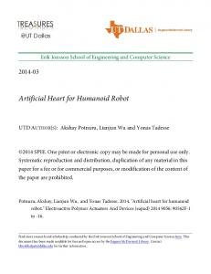
Fig. 1. Sky, a Disney A100 Audio-Animatronics hydraulic humanoid robot
in the tight and highly dynamic interaction required between the human and robot. A robot that can juggle by itself or with other robots can be very impressive, but merely showcases the repeatability and precision expected in robotic motion. Juggling with a human partner demonstrates an ability to react and respond to human inconsistency, potentially resulting in more life-like motion and an increased sense of realism. Robots capable of catching and throwing have been investigated previously. One of the first ball catching robots applications was based on fitting a parabola to the vision data and matching the robot trajectory to the ball trajectory [1]. Catching a ball with a humanoid wearing a baseball glove has been studied by Riley and Atkeson [2]. The movements were generated using movement primitives. Catching balls is also possible without reconstructing the 3D ball position by visual servoing [3], [4]. A robot tossing a cellphone and catching it again has been studied at the University of Tokyo [5]. The approach is based on high-speed sensory-motor fusion. Nonprehensile Ball Catching has been studied in [6] where the ball trajectory is predicted using recursive least squares. Catching a ball thrown towards a robot has been achieved by planning [7] and supervised learning [8] at DLR. The corresponding perception system are based on background subtraction [9] or circle detectors [10], [11] and Kalman Filters. The complete DLR system is discussed in [12]. Robot juggling has been studied by Aboaf et al. [13], [14]. The juggling task here corresponds to hitting a ball with a
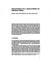
Robot
1.8m
Human
Cameras
2.
5m
2.0m
60cm
42cm
2.2m
Fig. 2. Graphical overview of our experimental setup for catching and throwing with a humanoid robot. The participant stands on a stool to be at equal level with the robot. A ASUS Xtion PRO LIVE camera system acquires the 3D position of the ball. Both the camera and the robot can only be used indoors.
paddle. Rizzi et al. [15], Yu et al. [16], as well as Schaal et al. [17]–[19] studied similar tasks. Juggling balls with a single arm and a funnel shaped hand has been studied by Sakaguchi et al. [20], [21]. Atkeson et al. studied juggling three balls in a cascade pattern with a Sarcos humaoid robot [22]. We believe we are the first to demonstrate human to robot partner juggling. II. S YSTEM D ESCRIPTION An overview of our experimental setup for throwing and catching is shown in Fig. 2. A description of the robot hardware is in Section II-A. The vision system is discussed in Sections II-B and II-C, and the robot software in Sections II-D through II-G. A. Robot Hardware We use Sky, a Walt Disney Imagineering A100 AudioAnimatronics figure (Fig. 1) with 39 degrees-of-freedom, 38 of which are driven by hydraulic actuators. This type of robot platform is currently commonly employed in the theme parks. The robot stands on a 60cm base containing its hydraulic valve manifold, pressure transducers, and computer connections. Its feet are fixed to the base so stability and balance are not a concern. For throwing and catching we use the left arm, which has seven degrees of freedom plus five fingers with one degree of freedom each. For additional motions such as orienting the robot towards the participant, simulating ball following, and acknowledging catching failure, we additionally use the pelvis, torso, shoulder shrugs, neck and eyes. The control system allows for the update of desired joint position set-points at 30Hz, a rate considered quite slow for reactive control. However, as this robot was designed only for pre-recorded trajectory playback, it is a limitation we must cope with. Lower level hydraulic valve controllers realize the desired positions of each actuator at
Fig. 3. Detail of the robot’s catching hand. The palm of the hand is approximately 10cm square.
a control loop of 1kHz. The maximal hand velocities is approximately 1.5m/s. We augmented the left hand of the robot with a plate to cover and protect the finger actuators and a foam rim to provide a more cup-like shape suitable for catching (Fig. 3). Our goal was to maintain as much of a human-like appearance as possible. B. Vision System As the robot has no onboard cameras in its eyes or elsewhere, we use an external camera system to acquire the 3D position of the balls. We employ a low cost offthe-shelf ASUS Xtion PRO LIVE, which contains both a depth and color camera, and does not require internal and external calibration of a stereo camera setup. This camera is almost identical to the Microsoft Kinect but supports hardware synchronization of the color and depth stream. The camera runs at 30Hz, the same as the control rate of the robot, thus avoiding aliasing. Ball detection is done with OpenCV, which obtains the registered color and depth images from the Xtion via OpenNI. The color image is a standard 640x480 8bit RGB image. An overview of our vision pipeline is shown in Fig. 4. The first step is to remove the foreground and the background by creating a mask based on a thresholded depth image. The color image is then masked and converted to HSV space. HSV is a convenient space to threshold on color while being invariant to illumination. Small false positives are removed by morphological operations. We run a Hough circle detector on the resulting image, which rejects larger false positives and yields the centers of the balls in the image plane in pixels. We average the depth value of the pixels that are active both in the color and the depth mask to obtain the depth of the balls1 . From the pixel position, focal length, and depth value, the complete Cartesian position can be reconstructed. The whole processing takes approximately 30ms. Using the same camera, but a separate processing pipeline, we additionally track the user’s location via the OpenNI skeleton tracker. From the skeleton information, we can isolate the 3D position of the user’s head, which we use to orient the robot towards the user and set its gaze to be looking at the participant. 1 The resulting offset in camera direction is negligible and would be compensated by the data-driven calibration.
Fig. 4.
Overview of the processing steps in the vision system.
C. Ball Filtering and Prediction
E. Catching Algorithm
The vision system obtains the Cartesian positions of the balls. In order to predict the catching position for the hand, we also need ball velocities. As the distance is short and the balls are relatively heavy (approx. ø 7cm, 100g), modeling the air drag did not improve the prediction and the balls can be modeled as point masses, i.e.:
The robot receives the predicted catching position as well as the predicted time until the catch from the vision system. If the predicted catching position is within the robot’s catching region, the hand is moved to the new position. Due to the low control frequency, we employ filtered step functions as desired trajectories for this task. At the time of predicted catch the fingers are closed as much as possible to trap the ball, however, the fingers are not capable of fully enclosing the ball and preventing it from escape. Other than our vision system, we have no means to detect success of a caught ball (e.g. no contact sensor or switch on the palm). Because the vision system sometimes sees the ball in the hand, it can lead to strange behaviors if the robot continues to try to catch the ball even if it is already caught. Consequently we stop updating the predicted catching position and catch time if there is less than 66ms until catch (two control cycles). This cutoff also prevents very fast movements when the ball is landing in the hand, which sometimes led to the robot hitting the ball and having it bounce off. 1) Inverse Kinematics Algorithm: Inverse kinematics is required to map the desired hand catching position to joint commands. Most inverse kinematics approaches work in the reference frame of the robot. Thus we would have
x (t) = x0 + v0 t + a0 t2 ,
(1)
where t is the time, x0 the initial position, v0 the initial velocity, and a0 the initial acceleration. In order to predict the ball trajectory, we need to estimate the initial values. We evaluated keeping the initial acceleration fixed to a0 = [0 0 − 9.81] m/s2 but found that the prediction is better if we keep this parameter open as the camera may not be precisely aligned to gravity. Using all previously seen ball positions and estimating the parameters in a least squares sense, required too many samples to converge and the robot did not manage to catch reliably as the initial predictions were too far off. We use a linear Kalman filter instead that is re-initialized every time a new ball is thrown. The initialization values are obtained by finite difference. A standard deviation of 5cm and 5mm for the measurement and process noise respectively worked well in practice. The robot always attempts to catch the ball on a predefined horizontal plane. Using Eq. (1), the time at which the ball trajectory intersects this plane is calculated. Then the corresponding intersection position can be determined. D. Robot State Machine For our catching game, the robot continually waits for a ball to catch, and throws it back soon after catching. We implement this behavior as a state machine (Fig. 5). Catching (Section II-E) and throwing (Section II-F) are two distinct states and we additionally include two states to handle the smooth transitions in between catching and throwing. If the robot does not catch the ball, we transit to a missed ball state (Section II-G2) and return to the waiting position for a new ball. Switching from the catching state to the transition or the missed ball state is tied to the predicted catching time and the ball position. All other transitions occur after a fixed amount of time has elapsed.
Fig. 5. The robot’s state machine and transition diagram. Photos indicate the end positions of each state.
0.1
0.1
0
0
−0.1
−0.1
−0.2
−0.2
1 0.9 0.8
y in [m]
y in [m]
0.7
good transit joint limit
−0.3
0.6
−0.3
−0.4
−0.4
−0.5
−0.5
−0.6
−0.6
0.5 0.4 0.3 0.2
−0.6
−0.5
−0.4
−0.3 −0.2 x in [m]
−0.1
0
0.1
0.1
−0.6
−0.5
−0.4
−0.3 −0.2 x in [m]
−0.1
0
0.1
0
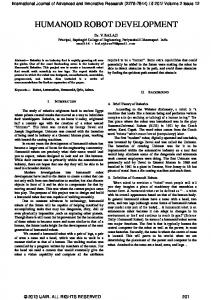
Fig. 6. This figure illustrates top-down view of the feasible catching region of the robot. The robot stands at position (0,0) and is facing to the left. The region is determined by the workspace of the hand before hitting a joint limit (blue). The linear inverse kinematics algorithm performs well (position error less than size of catching hand) in almost the whole region (red). IK error increases in the cyan region but the robot manages nevertheless to catch reliably in the lower left-hand region, see Fig. 7. The average error in the red area is 3cm and 15cm in the cyan area. Slight overlap between red and blue regions is due to joint limits effectively forcing the hand to move out of the sampling plane.
Fig. 7. This figure illustrates the catching performance of the robot. The view is identical to Fig. 6. The color-scale indicates the success rate at a given location. The black outline marks the feasible catching region (red region in Fig. 6) and the black star indicates the default hand position. The figure shows average results for 200 throws by novice users and 400 throws by expert users. Within the feasible catching region the success rate is 75%. The data was smoothed and normalized regionally to produce this plot. Due to the shape of the hand and having balls always fly predominantly in a positive x-direction, the robot also performs well catching balls to the right and below the feasible catching region.
to additionally calibrate the robot’s reference frame to the camera’s. Instead we decided to use a single local linear model that combines both the vision-to-robot calibration and the inverse kinematics. Because catching always occurs on the same horizontal plane in a fairly limited region, the mapping from Cartesian positions to joint angles can be approximated as linear. The position θi of joint i is expressed as a function of the Cartesian position (x, y, z) in the following form:
less than the variance compensated by the size of the hand (