Omron Connector for multidrop connections using thick cables. ... RS-232C to RS
-232C for PLC communication; cable length 2 m ..... Application Example: ..... It
may represent the result of Seller s test conditions, and the user must corre.
Micro Programmable Controller
CPM1A
The CPM1A series micro controllers solve both basic and semi-complex applications. The brick style models include DC inputs/transistor or relay outputs to meet your design requirements. The base I/O for the CPUs ranges from 10, 20, 30, and 40 I/O points with maximum expansion to 100 I/O. Specialized expansion modules include mixed analog I/O, temperature sensor inputs and serial communications. D D D D D D D D D
10, 20, 30 and 40 point I/O CPUs Expandable up to 100 I/O points Peripheral communications port built in DC input models Analog expansion modules available Temperature sensor input expansion modules available Auxiliary 24 VDC supply (AC type only) Relay or Transistor outputs UL, CSA, CE approvals
Basic Configuration CPM1-CIF01/CIF11 Serial Communications Adaptor
A--22
Micro Programmable Controller
CPM1A
Ordering Information J CPU Stock Note: Shaded models are normally stocked. Number of t i l I/O terminals
Inputs p
10
6 DC points p
20 30 40
Outputs p
12 DC points p 18 DC points p 24 DC points p
4 points p 8 points p 12 p points 16 p points
Power l supply
Part number Sink type
Source type
AC
CPM1A-10CDR-A-V1
CPM1A-10CDT-A-V1
CPM1A-10CDT1-A-V1
DC
CPM1A-10CDR-D-V1
CPM1A-10CDT-D-V1
CPM1A-10CDT1-D-V1
AC
CPM1A-20CDR-A-V1
CPM1A-20CDT-A-V1
CPM1A-20CDT1-A-V1
DC
CPM1A-20CDR-D-V1
CPM1A-20CDT-D-V1
CPM1A-20CDT1-D-V1
AC
CPM1A-30CDR-A-V1
CPM1A-30CDT-A-V1
CPM1A-30CDT1-A-V1
DC
CPM1A-30CDR-D-V1
CPM1A-30CDT-D-V1
CPM1A-30CDT1-D-V1
AC
CPM1A-40CDR-A-V1
CPM1A-40CDT-A-V1
CPM1A-40CDT1-A-V1
DC
CPM1A-40CDR-D-V1
CPM1A-40CDT-D-V1
CPM1A-40CDT1-D-V1
Relay y output p
Transistor output
J EXPANSION I/O MODULES Stock Note: Shaded models are normally stocked. Description
Max. number of modules
Inputs
Outputs
Part number
20 I/O / points p
3 max. (S Note.) (See N t )
24 VDC
Relays
CPM1A-20EDR1
24 VDC
Sinking transistors
CPM1A-20EDT
24 VDC
Sourcing transistors
CPM1A-20EDT1
8 inputs
24 VDC
—
CPM1A-8ED
8 outputs p
—
Relays
CPM1A-8ER
—
Sinking transistors
CPM1A-8ET
—
Sourcing transistors
CPM1A-8ET1
12 inputs, p , 8 outputs t t
Note: A maximum of 3 expansion modules can be used with the following CPUs: 30-point and 40-point with DC inputs.
Micro Programmable Controller
CPM1A
A--23
J DEDICATED I/O MODULES Stock Note: Shaded models are normally stocked. Description
Max. number of modules
Inputs
Outputs
Part number
Analog I/O Module 2 analog inputs (2 words) 1 analog output (1 word)
3 max.
2 analog inputs
1 analog output
CPM1A-MAD01
Temperature p S Sensor Input I t Modules
Thermocouple p i inputs t
3 max.
2 inputs (Types J and K)
1 max. (See Note.)
4 inputs (Types J and K)
CPM1A-TS002
Platinum resistance th thermometer t inputs i t
3 max.
2 inputs (Pt100, JPt100)
CPM1A-TS101
3 max.
2 inputs (Pt100, JPt100)
1 analog output
CPM1A-TS101-DA
1 max. (See Note.)
4 inputs (Pt100, JPt100)
—
CPM1A-TS102
3 max.
8 bits (Inputs from the Master.)
8 bits (Outputs to the Master.)
CPM1A-SRT21
CPM1A-MAD11
CompoBus/S I/O Link Module 8 inputs and 8 outputs
DeviceNet I/O Link Module 32 inputs and 32 outputs
Profibus--DP Slave Module 16 6 inputs puts and a d 16 6 outputs
—
CPM1A-TS001
Flat cable, 4-core, 0.75 mm2; 100 m length
SCA1-4F10
Twisted pair cable, 2-core, 0.75 mm2; available commercially
Belden #9409 cable
3 max.
CPM1A-DRT21
32 bits (Inputs from the Master.)
32 bits (Outputs to the Master.)
Omron connector with screws (included with DeviceNet I/O Link Module).
XW4B-05C1-H1-D
Omron Connector for multidrop connections using thick cables.
XW4B-05C4-TF-D
3 max.
CPM1A-PRT21
16 bits (Inputs from the Master.)
16 bits (Outputs to the Master.)
Shielded twisted pair cable, available commercially
Belden #3079A cable
Note: Only one CPM1A-TS002/TS102 Temperature Sensor Input Module can be connected to the CPU. If a CPM1A-TS002/102 is connected to the CPU, only one additional Special I/O Module (other than a CPM1A-TS002/102) or one Expansion I/O Module can be connected to the CPU.
J PERIPHERAL DEVICES Stock Note: Shaded models are normally stocked. Product
Description
Part number
Programming g g console
Hand-held programming console with cable attached, 2 m length
CQM1-PRO01--E
Hand-held programming console with back light (cable not included)
C200H-PRO27-E
Connects C200H programming console to peripheral port, 2 m length
C200H-CN222
Connects C200H programming console to peripheral port, 4 m length
C200H--CN422
Connecting g cable
J SUPPORT SOFTWARE Stock Note: Shaded models are normally stocked. Product
Functions
Part number
CX-Programmer Jr.
Windows-based programming software; reduced instruction set and networking commands.
WS02-CXPC1-EJ-V__
CX-Programmer
Full programming software package programs micro, small and larger controllers.
WS02-CXPC1-E-V__
A--24
Micro Programmable Controller
CPM1A
J COMMUNICATIONS ADAPTERS AND CABLES Stock Note: Shaded models are normally stocked. Description
Function
Part number
RS-232C adapter
Converts data communications from peripheral port for RS-232C devices.
CPM1-CIF01
RS-232C cable
RS-232C to RS-232C;; PC connection for program p g download;; cable bl length l th 2 m
C200H-CN229-EU
RS-232C to RS-232C for PLC communication;; cable length g 2m
C200H-CN320-EU
CBL-202* CBL-804*
Communication cable for NT31C (port (p B only) y)
RS-422/RS-485 adapter
50 cm
NT31C-CN510-EU
3m
NT31C-CN320-EU
5m
NT31C-CN520-EU
Converts data communications from peripheral port for RS-422/RS-485 devices.
CPM1-CIF11
* Available in Canada only.
J PROGRAM TRANSFER EQUIPMENT Stock Note: Shaded models are normally stocked. Product
Description
Part number
Expansion Memory Unit
Uploads and downloads program and setup memory areas to and from the controller.
CPM1-EMU01-V1
EEPROM (256 kbits)
Used with the Expansion Memory Unit
EEPROM-CPM1-EMU01
Product
Description
Part number
Operation manual
CPM1A programmable controllers operation manual
W317
Programming manual
CPM1/CPM1A/CPM2A/CPM2C/SRM1(-V2) programming manual
W353
J MANUALS
Micro Programmable Controller
CPM1A
A--25
Specifications J GENERAL SPECIFICATIONS Input type
DC input
CPU type
10-point I/O
20-point I/O
30-point I/O
Power supply voltage/fre voltage/frequency
AC power supply
100 to 240 VAC, 50/60 Hz
DC power supply
24 VDC
Operating p g voltage lt range
AC power supply
85 to 264 VAC
DC power supply
20.4 to 26.4 VDC
Power ti consumption
AC power supply
30 VA max.
60 VA max.
DC power supply
6 W max.
20 W max.
30 A max.
60 A max.
Inrush current External power supply supp y ((AC C only) o y)
Power supply voltage
24 VDC
Power supply output capacity
200 mA
40-point I/O
300 mA
Insulation resistance
20 MΩ min. at 500 VDC between the AC terminals and the protective earth terminal.
Dielectric strength
2,300 VAC at 50/60 Hz for one minute with a leakage current of 10 mA max. between all the external AC terminals and the protective earth terminal.
Noise resistance
Conforms to IEC61000-4-4, 2 kV (power lines) 1500 Vp-p, pulse width 0.1 to 1 µs, rise time: 1 ns (via noise simulation)
Vibration resistance
10 to 57 Hz with an amplitude of 0.075 mm, and 57 to 150 Hz with an acceleration of 1.5 G in the X, Y, and Z directions for 10 sweeps of minutes each.
Shock resistance
147 m/s2 in the X, Y and Z directions 3 times each.
Ambient t temperature t
Operating Storage
--20°C to 75°C (--4°F to 167°F)
Ambient humidity
Operating
10% to 90% RH no condensation
Ambient environment
Operating
With no corrosive gas
0°C to 55°C (32°F to 131°F)
Terminal screw size
M3
Power supply holding time
10 ms min. for AC models, and 2 ms min. for DC models
CPU Weight g
AC models
400 g max.
500 g max..
600 g max..
700 g max.
DC models
300 g max.
400 g max.
500 g max.
600 g max.
Expansion Weight
A--26
Units with 20 I/O points:
300 g max.
Units with 8 output points:
250 g max.
Units with 8 input points:
200 g max.
MAD01 Analog I/O unit:
150 g max.
MAD11 Analog I/O unit:
250 g max.
Temperature sensor units:
250 g max.
CompoBus/S I/O link unit:
200 g max.
DeviceNet I/O link unit:
200 g max.
Profibus-DP slave unit:
125 g
Micro Programmable Controller
CPM1A
J CHARACTERISTICS Input type
DC input
CPU type
10-point I/O
Control method
Stored program method
I/O control method
Combination of the cyclic scan and immediate refresh processing methods.
Programming language
Ladder diagram
Instruction word
1 step per instruction, 1 to 5 words per instruction
20-point I/O
Types yp of i t ti instructions
Basic instructions
14 types
Special instructions
79 types, 139 instructions
Instruction execution time
Basic instructions
0.72 to 16.2 µs
Special instructions
MOV instruction = 16.3 µs
30-point I/O
40-point I/O
Program capacity
2,048 words
User data memory
1,024 words
Maximum I/O points
CPU only
10 points (6 input/ 4 output points)
20 points (12 input/ 8 output points)
30 points (18 input/ 12 output points)
40 points (24 input/ 16 output points)
With Expansion I/O Module
—
—
Up to 90 points (54 input/ 36 output points)
Up to 100 points (60 input/ 40 output points)
Memory protection
Maintains the contents of the HR, AR, Counter and Data Memory Areas.
Memory backup
Flash memory: Super capacitor:
User program, data memory (Read only) and PLC setup area are backed up without a battery. Data memory (Read/Write), holding bits, auxiliary memory bits, counter values, error log area are backed up by a capacitor for 20-days at an ambient temperature of 25°C.
Self-diagnostic function
CPU error (watchdog timer), memory errors, I/O bus errors
Program check
No END instruction programming errors (constantly checked during operation)
Pulse output
1 point:
High-speed counter
1 point: Single phase at 5 kHz or two-phase at 2.5 kHz (linear counting method) Incremental mode: 0 to 65535 (16-bit) Decremental mode: --32767 to 32767 (16-bit)
Quick-response inputs
Together with the external interrupt input (minimum pulse width of 0.2 ms)
Input time constant
Can be set at 1 ms, 2 ms, 4 ms, 8 ms, 16 ms, 32 ms, 64 ms, or 128 ms.
Interrupt processing: External interrupt
2 points (Response time of 0.3 ms max.)
Analog settings
2 points: (0 to 200 BCD)
2 kHz
4 points (Response time of 0.3 ms max.)
J I/O ALLOCATION Input bits
00000 to 00915; words not used for input or output bits can be used for work bits.
Output bits
01000 to 01915; words not used for input or output bits can be used for work bits.
Work bits (IR Area)
512: IR 20000 to IR 23115 (IR 200 to IR 231)
Special bits (SR Area)
384: SR 23200 to SR 25515 (SR 232 to SR 255)
Temporary bits (TR Area)
8: TR 0 to TR 7
Holding bits (HR Area)
320: HR 0000 to HR 1915 (HR 00 to HR 19)
Auxiliary bits (AR Area)
256: AR 0000 to AR 1515 (AR 00 to AR 15)
Link bits (LR Area)
256: LR 0000 to LR 1515 (LR 00 to LR 15)
Timers/Counters
128: TIM/CNT 000 to 127 100-ms timer: TIM 000 to TIM 127 10-ms timer: TIM 000 to TIM 127 Decremental counter, reversible counter
Data memory y
Read/Write
1,024 words (DM 0000 to DM 1023)
Read only
512 words (DM 6144 to DM 6655)
Micro Programmable Controller
CPM1A
A--27
J I/O SPECIFICATIONS CPU DC Input Item
Specifications
Input voltage
24 VDC +10%/ --15%
Circuit
Input impedance
IN0000 to IN0002: 2 kΩ Others: 4.7 kΩ
Input current (typical)
IN0000 to IN0002: 12 mA Others: 5 mA
ON voltage
14.4 VDC min.
OFF voltage
5.0 VDC max.
ON delay (See Note 1)
1 to 128 ms max. (default: 8 ms) (See Note 1)
OFF delay (See Note 1)
1 to 128 ms max. (default: 8 ms) (See Note 1)
Input LED 4.7 kΩ IN
Internal Circuits
4.7 kΩ
COM
Note: The polarity of the input power supply can be either positive or negative.
Note: 1. The actual ON/OFF delay includes an input constant of 1, 2, 4, 8, 16, 32, 64, or 128 ms (default: 8 ms). 2. When IN0000 to IN0006 are used for the high-speed counter inputs, the delays are as shown below: Input
Increment mode
Differential phase mode
IN0000 (A-phase)
5 kHz
2.5 kHz
IN0001 (B-phase)
Normal input
IN0002 (Z-phase)
ON: 100 µs max. OFF: 500 µs max.
IN0003 to IN0006
0.3 ms max. (From the time of input ON until the interrupt subroutine is executed.)
Expansion I/O Unit Item
Specifications +10%/
Circuit
Input voltage
24 VDC,
Input impedance
4.7 kΩ
Input current (typical)
5 mA
ON voltage
14.4 VDC min.
IN
OFF voltage
5.0 VDC max.
COM
ON delay
1 to 128 ms max. (default: 8 ms) (See Note)
OFF delay
1 to 128 ms max. (default: 8 ms) (See Note)
--15%
IInputt LED 4.7 kΩ Internal e a Ci it Circuits
4 7 kΩ 4.7
Note: The polarity of the input power supply can be either positive or negative.
Note: The actual ON/OFF delay includes an input constant of 1, 2, 4, 8, 16, 32, 64, or 128 ms (default: 8 ms).
J OUTPUT SPECIFICATIONS (CPU AND EXPANSION I/O MODULES) Relay Output Item
Specifications
Maximum switching capacity
2 A, 250 VAC (cos φ =1) 2 A, 24 VDC (4 A/common)
Minimum switching capacity
10 mA, 5 VDC
Relay service lif life
Resistance load
150,000 times
Inductive load
100,000 times
Electrical
Mechanical
Output LED
Internal Circuits
OUT
OUT COM
20 million times
ON delay
15 ms max.
OFF delay
15 ms max.
A--28
Circuit
Micro Programmable Controller
Maximum 250 VAC: 2 A 24 VDC: 2 A
CPM1A
Transistor Outputs (Sinking) Item
Specifications CPM1A10CDT-j(-V1)
Max. switching capacity p y
CPM1A20CDT-j(-V1)
CPM1A30CDT-j(-V1)
CPM1A40CDT-j(-V1)
CPM1A-20EDT
24 VDC +10%/--15%, 0.3 A/point (See note)
0.9 A/Unit
0.9 A/common 1.8 A/Unit
CPM1A-8ET 4.5 to 30 VDC 0.2 A (See note 2.) 0.3 A (See note 3.)
0.9 A/common 2.7 A/Unit
0.9 A/common 3.6 A/Unit
Leakage current
0.1 mA max.
Residual voltage
1.5 V max.
ON delay
0.1 ms max.
OFF delay
OUT01000/01001: 0.2 ms max. (load current: 100 to 300 mA) 0.5 ms max. (load current: 5 to 100 mA)
0.9 A/common 1.8 A/Unit
1 ms max. (24 VDC +10%/ --15%, 5 to 300 mA)
Other than OUT01000/01001: 1 ms max. (load current 5 to 300 mA) Fuse
V1 CPUs: No fuse Expansion I/O Units and Pre-V1 CPUs. 1.25 A/common (cannot be replaced by the user)
Circuit configuration
Transistor Outputs (Sourcing) Item
Specifications CPM1A10CDT1-j(-V1)
Max. switching capacity p y
CPM1A20CDT1-j(-V1)
CPM1A30CDT1-j(-V1)
CPM1A40CDT1-j(-V1)
CPM1A-20EDT1
24 VDC +10%/--15%, 0.3 A/point (See note)
0.9 A/Unit
0.9 A/common 1.8 A/Unit
CPM1A-8ET1 4.5 to 30 VDC 0.2 A (See note 2.) 0.3 A (See note 3.)
0.9 A/common 2.7 A/Unit
0.9 A/common 3.6 A/Unit
Leakage current
0.1 mA max.
Residual voltage
1.5 V max.
ON delay
0.1 ms max.
OFF delay
OUT01000/01001: 0.2 ms max. (load current: 100 to 300 mA) 0.5 ms max. (load current: 5 to 100 mA)
0.9 A/common 1.8 A/Unit
1 ms max. (24 VDC +10%/ --5%, 5 to 300 mA)
Other than OUT01000/01001: 1 ms max. (load current 5 to 300 mA) Fuse
V1 CPUs: No fuse Expansion I/O Units and Pre-V1 CPUs. 1.25 A/common (cannot be replaced by the user)
Circuit configuration
Note: When using the OUT01000 or OUT01001 as a pulse output, connect dummy resistors as required to set the load current to 0.1 to 0.2 A. If the load current is below 0.1 A, the ON-to-OFF response time will become longer and high-speed pulse will not be output. On the other hand, if the load current is above 0.2 A, the transistor may generate heat and components may be damaged.
Micro Programmable Controller
CPM1A
A--29
J ANALOG I/O MODULE CPM1A-MAD01 Specifications Item
Specification
Model
CPM1A--MAD01
I/O type
Voltage
Analog g inputs p
Analog g output p (S N (See Note t 1 1.))
Current
Number of inputs
2
Input signal range
0 to 10 V or 1 to 5 V
4 to 20 mA
Maximum rated input
±15 V
±30 mA
External input impedance
1 MΩ min.
250 Ω rated
Resolution
1/256
Overall precision
1.0% of full scale
Converted A/D data
8-bit binary
Number of outputs
1
Output signal range
0 to 10 V or --10 to 10 V
4 to 20 mA
External output max. current
5 mA
—
External output allowed load resistance
—
350 Ω
Resolution
1/256 (1/512 when the output signal range is --10 to 10 V.)
Overall precision
1.0% of full scale
Data setting
8-bit binary with sign bit
Conversion time (See Note 2.)
10 ms/Unit max.
Isolation method
Photocoupler isolation between I/O terminals and PC (There is no isolation between the analog I/O signals.)
Note: 1. The voltage output and current output can be used at the same time, but the total output current cannot exceed 21 mA. 2. The conversion time is the total time for 2 analog inputs and 1 analog output.
A--30
Micro Programmable Controller
CPM1A
CPM1A-MAD11 Specifications Item
Specification
Model
CPM1A--MAD11
I/O type
Voltage
Analog g inputs p
Current
Number of inputs
2 inputs (2 words allocated)
Input signal range
0 to 5 VDC, 1 to 5 VDC 0 to 10 VDC, --10 to 10 VDC
0 to 20 mA or 4 to 20 mA
Maximum rated input
±15 V
±30 mA
External input impedance
1 MΩ min.
250 Ω
Resolution
1/6000 (full scale)
Overall accuracyy
25_C
0.3% full scale
0.4% full scale
0 to 55_C
0.6% full scale
0.8% full scale
Converted A/D data
16-bit binary (4-digit hexadecimal) Full scale for --10 to 10 V: F448 to 0BB8 Hex Full scale for other ranges: 0000 to 1770 Hex
Analog g output p
Averaging function
Supported (Settable for individual inputs via DIP switch)
Open-circuit detection function
Supported
Number of outputs
1 output (1 word allocated)
Output signal range
1 to 5 VDC, 0 to 10 VDC, or --10 to 10 VDC
0 to 20 mA or 4 to 20 mA
Allowable external output load resistance
1 kΩ min.
600 Ω max.
External output impedance
0.5 Ω max.
—
Resolution
1/6000 (full scale)
Overall accuracyy Set data (D/A conversion)
25_C
0.4% full scale
0 to 55_C
0.8% full scale 16-bit binary (4-digit hexadecimal) Full scales for --10 to 10 V: F448 to 0BB8 Hex Full scale for other ranges: 0000 to 1770 Hex
Conversion time
2 ms/point (6 ms/all points)
Isolation method
Photocoupler isolation between analog I/O terminals and internal circuits. No isolation between analog I/O signals.
Micro Programmable Controller
CPM1A
A--31
J TEMPERATURE SENSOR MODULES By connecting a Temperature Sensor Module (CPM1A-TS001/TS002/TS101/TS101A/TS102) to the CPM1A, inputs can be received from thermocouples or temperatureresistance thermometers. Inputs converted to binary data (4-digit hexadecimal) and stored in the IR area.
Specifications Item
Specification
Model
CPM1A-TS001/TS002
CPM1A-TS101/TS102
CPM1A-TS101-DA
Number of inputs
TS001: 2; TS002: 4
TS101: 2; TS102: 4
2
Input types (See Note 1)
Thermocouple types K or J, selectable
Platinum resistance thermometer types Pt100 and JPt1100, selectable
Input resolution
0.1°C in 2’s complement format
0.1°C in 2’s complement format
Input accuracy
±0.5% or ±2% of the stored value whichever is larger ±1 digit max. (See Note 2)
±0.5% or ±1% of the stored value whichever is larger ±1 digit max. (See Note 2)
1.0% max. full scale
Number of outputs
None
None
1
Output types
—
—
Voltage or current output
Output resolution
—
—
1/256 (0 to 10 V) 1/512 (--10 to +10 V) 1/256 (4 to 20 mA)
Output accuracy
—
—
1.0% max. full scale
Conversion cycle
250 ms for all points
60 ms max. for all points
Converted temperature data
Binary data (4-digit hexadecimal)
Binary data (8-digit hexadecimal)
Isolation method
Photocoupler isolation between I/O terminals and the PLC
Note: 1. The same input type must be used for all inputs. 2. Accuracy for K thermocouples at temperatures less than --100°C: ±4°C ± 1 digit max.
Input Temperature Ranges for CPM1A-TS001/TS002 The rotary switch can be used to make of the following range and input type settings for CPM1A-TS001/002 models. Thermocouple input
Range (°C)
Type yp K
--200 to 1300
--300 to 2300
0.0 to 500.0
0.0 to 900.0
Type yp J
Range (°F)
--100 to 850
--100 to 1500
0.0 to 400.0
0.0 to 750.0
Input Temperature Ranges for CPM1A-TS101/TS101DA/TS102 The rotary switch can be used to make of the following range and input type settings for CPM1A-TS101/102 models. Platinum RTD input
Range (°C)
Range (°F)
Pt100
--200.0 to 650.0
--300 to 1200.0
JPt100
--200.0 to 650.0
--300 to 1200.0
A--32
Micro Programmable Controller
CPM1A
J COMMUNICATIONS ADAPTER RS-232C Adapter and RS-422 Adapter
CPM1-CIF01
CPM1-CIF11
Model
CPM1-CIF01
CPM1-CIF11
Functions
Level conversion between the CMOS level (CPU side) and the RS-232C (peripheral device side)
Level conversion between the CMOS level (CPU side) and the RS-422 (peripheral device side)
Insulation
The RS-232C (peripheral device side) is insulated by a DC/DC converter and photocoupler.
The RS-422 (peripheral device side) is insulated by a DC/DC converter and photocoupler.
Power supply
Power is supplied by the CPU.
Power consumption
0.3 A max.
Transmission speed
38.4 kbits/s max.
Vibration resistance
10 to 57 Hz with an amplitude of 0.075 mm, and 57 to 150 Hz with an acceleration of 1 G in the X, Y and Z directions for 80 minutes each (i.e. for 8 minutes each, 10 times).
Shock resistance Ambient temperature p
1.5 G in the X, Y and Z directions 3 times each. Operating
0°C to 55°C (32°F to 131°F)
0°C to 55°C (32°F to 131°F)
Storage
--20°C to 75°C (--4°F to 167°F)
--20°C to 75°C (--4°F to 167°F)
Ambient humidity
Operating
10% to 90% RH (with no condensation)
Ambient environment
Operating
With no corrosive gas
Weight
200 g max.
J COMPOBUS/S I/O LINK MODULE The CPM1A controller can function as a Slave to a CompoBus/S Master Module (or SRM1 CompoBus/S Master Control Module) when a CPM1A-SRT21 CompoBus/S I/O Link Module is connected. The CompoBus/S I/O Link Module establishes an I/O link of 8 inputs and 8 outputs between the Master Module and the CPM1A. Up to 3 Expansion I/O Modules or Expansion Modules can be connected to a CPM1A CPU. CompoBus/S Master Module (or SRM1 CompoBus/S Master Control Module)
CPM1A CPU
CPM1A-SRT21 CompoBus/S I/O Link Module
CS1j, C200Hj, CQM1 (H), or CJ1 (M), CPM2C-S Flat cable SCA1-4F10 or twisted pair Belden #9409 cable
Up to 16 Slaves can be connected. (Up to 8 Slaves with the CQM1-SRM21-V1.)
Specifications Model
CPM1A-SRT21
Master/Slave
CompoBus/S Slave
Number of I/O bits
8 input bits, 8 output bits
Number of words occupied in CPM2A I/O memory
1 input word, 1 output word (Allocated in the same way as other Expansion I/O Modules or Expansion Modules)
Node number setting
Set using the DIP switch.
Note: See the CompoBus/S section of Omron’s Remote I/O and Wiring Solutions Catalog (GC RIO1) for more details on CompoBus/S communications.
Micro Programmable Controller
CPM1A
A--33
J DEVICENET I/O LINK MODULE The CPM1A controller can function as slaves to a DeviceNet Master when a DeviceNet I/O Link Module is connected. The DeviceNet I/O Link Module establishes an I/O link of 32 inputs and 32 outputs between the master and the controller. A maximum of 3 DeviceNet I/O Link Modules can be connected to a CMP1A to create I/O Links for up to 192 points (96 inputs and 96 outputs).
PC supporting DeviceNet master, e.g., CS1, C200HX/HG/HE (-Z), CV-series, CJI(M)
Specifications Item
Specification
Model number
CPM1A-DRT21
Master/slave
DeviceNet Slave
Number of I/O points
32 input points, 32 output points
Number of words allocated in CPU Unit I/O memory
2 input words, 2 output words
Node number setting
Set using the rotary switches
(Allocated in the same way as Expansion I/O Units and other Expansion Units) (Set before turning ON the CPU’s power supply.)
A--34
Micro Programmable Controller
CPM1A
J PROFIBUS-DP SLAVE MODULE The CPM1A--V1 controller can function as a slave to a Profibus-DP Master Module when a CMP1A-PRT Profibus-DP Slave Module is connected. The Profibus-DP Slave Module establishes an I/O link of 16 inputs and 16 outputs between the master and the controller. A maximum of 3 Profibus-DP Slave Modules can be connected to a CPM1A or CPM2A to create I/O links for up to 96 points (48 inputs and 48 outputs). Profibus-DP Master Module
PLC supporting Profibus-DP Master, e.g., CSI, C200Hj, CJ1j
CPM1A CPU
PRT21
Shielded twisted pair Belden #3079A cable
Each module enables remote I/O communications for 16 inputs and 16 output points as a Profibus-DP slave.
Up to 124 nodes (using repeaters)
Specifications Storage temperature
--20 to +75°C
Ambient temperature
0 to +55°C
Ambient humidity
10 to 90% (non-condensing)
EMC compliance
EN 50081-2, EN 61131-2
Current consumption
100 mA from the PLC I/O bus
Weight
125 g (typical)
Control data
From CPU to unit: none
Status data
From unit to CPU: none
I/O data (in bytes)
2 bytes input, 2 bytes output
Micro Programmable Controller
CPM1A
A--35
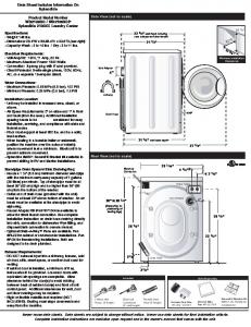
Dimensions Unit: mm (inch)
J CPU, EXPANSION I/O AND SPECIAL I/O MODULES
90 (3.54)
50 (1.97) DC power supply
W
70 (3.35) AC power supply
Model
W
CPM1A-10CDj-A/D-V1
66 (2.60)
CPM1A-20CDj-A/D-V1
86 (3.39)
CPM1A-30CDj-A/D-V1
130 (5.12)
CPM1A-40CDj-A/D-V1
150 (5.91)
CPM1A-20EDj
86 (3.39)
CPM1A-8Ej
66 (2.60)
CPM1A-SRT21
66 (2.60)
CPM1A-MAD01
66 (2.60)
CPM1A-TSjjj
86 (3.39)
CPM1A-MAD11
86 (3.39)
CPM1A-DRT21
66 (2.60)
CPM1A-PRT21
66 (2.60)
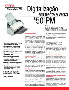
Unit: mm (inch)
J COMMUNICATION ADAPTER MODULES CPM1-CIF01
CPM1-CIF11 30 (1.18)
30 (1.18) 56 (2.20) 50
21
21
90 (3.54)
90 (3.54)
81
81
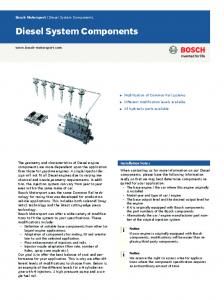
J DIMENSIONS WITH PERIPHERAL DEVICES ATTACHED CPU with DC Power Supply
CPU with AC Power Supply
Approx. 90 (3.54)
A--36
Micro Programmable Controller
Approx. 110 (4.33)
CPM1A
61 (2.40) 50
Functions J CONFIGURATION The CPM1A CPUs feature a compact, one-piece construction that includes 10, 20, 30 or 40 built-in I/O terminals. Three output models are available: Relay outputs, sinking (NPN) transistor output and sourcing (PNP) transistor output.
CPM1A-10CDj-j-V1 (10 I/O terminals)
CPM1A-20CDj-j-V1 (20 I/O terminals)
CPM1A-30CDj-j-V1 (30 I/O terminals)
CPM1A-40CDj-j-V1 (40 I/O terminals)
Expansion Up to three Expansion I/O Modules can be connected to a 30-point or 40-point CPU to add an extra 8 or 20 I/O points for each, for a maximum of up to 100 I/O points.
Dedicated I/O Modules Up to 3 Analog I/O Modules or Temperature Sensor Input Modules can be used with 30-point and 40-point CPUs. Each analog I/O module provides 2 analog inputs and 1 analog output, so a maximum of 6 analog inputs and 3 analog outputs can be achieved by connecting 3 Analog I/O Modules. Each Temperature Sensor Module provides two temperature sensor inputs from either thermocouples or platinum resistance thermometers. Up to 6 inputs can be connected.
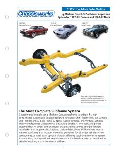
J INTERRUPT INPUTS There are two input interrupts in the CPM1A 10-point I/O CPU and four in the 20-, 30-, and 40-point I/O CPUs. Input interrupts are available in two modes. In addition to normal interrupt inputs, the CPM1A has a counter mode that counts high-speed input signals and triggers interrupts at fixed count multiples.
Application Example: 10 point I/O CPU
IR00003 IR00004
20, 30, and 40 point I/O CPU IR00003 IR00004 IR00005 IR00006
Cutting Metal Sheets to Specified Lengths The proximity sensor detects the edge of a metal plate to operate the cutter. Metal sheets can be cut continuously to the specified lengths at a high speed. Metal sheets
Cutter
Cutter operation signal
Conveyor
Proximity sensor Input interrupt
Micro Programmable Controller
CPM1A
CPM1A
A--37
Input Interrupt Mode If an input interrupt occurs, the regular program shuts down irrelevant of the cycle time, and the interrupt processing program is executed immediately.
Regular program
Regular program
Interrupt program
Input interrupt
Counter Mode When the number of external signals counted at high speed reaches a specified number of counts, the regular program shuts down, and the interrupt processing program is executed at fixed counts. The count can be set between 0 and 65535.
Regular program
Regular program
Interrupt program
Input interrupt
Counter setting
J QUICK-RESPONSE INPUTS Quick-response inputs can detect input signals with a pulse width as short as 0.2 ms regardless of their timing during the scan cycle. Quick-response inputs and interrupt inputs use the same input terminals.
CPU
Input no.
Minimum input pulse width
10 point I/O CPU
00003 to 00004
0.2 ms
20 point, 30 point, 40 point I/O CPU
00003 to 00006
Application Example: Overseeing processes
Program execution
I/O refreshing
Overseeing Program processes execution
I/O refreshing
Calculating the Number of Chips The metal sensor counts the number of parts that have passed. Steady counting can be achieved even when the input-ON time is short.
0.2 ms min Input signal (00003)
CPM1A IR 00003 One cycle F2LP-WK4 F2LP-W
A--38
Micro Programmable Controller
CPM1A
J HIGH-SPEED COUNTER The CPM1A has a high-speed counter function that can be used in the incrementing and up/down mode. Using this function together with the input interrupts enables zone comparison control or target value control irrelevant of the cycle time.
Counting mode
Incrementing mode
Up/Down mode
Input p no.
00000
Count input
A-phase input
00001
—
B-phase input
00002
Reset input
Z-phase input
Input method
Single-phase input
Phase-difference, 4× inputs
Count frequency
5.0 kHz
2.5 kHz
Count range
0 to 65535
--32767 to 32767
Note: When using in the incrementing mode, the input 00001 can be used as an input contact.
Micro Programmable Controller
CPM1A
A--39
J INTERVAL TIMER INTERRUPTS The CPM1A has one interval timer. The interval timer shuts down the regular program regardless of the point in the cycle once the time is up, and immediately executes an interrupt processing program. Interval timers are used in the following two modes. Item
One-shot mode
Scheduled interrupt mode
Operation
An interrupt is executed only once when the time is up.
Interrupts are executed repeatedly at fixed periods.
Setting time
0.5 ms to 319,968 ms (0.1-ms units)
Application Example:
Normal program
Computing the Sheet Speed The number of pulse inputs is computed in the interrupt mode at a fixed time to calculate the speed.
Interval timer MOV(21) ADD(30)
CPM1A
Interrupt processing program Encoder SBN(92) 00
MOV(21)
RET(93) END(01)
J ANALOG SETTING The CPM1A contains two analog setting controls that can be used for a broad range of analog timer and counter settings. Turning the setting control stores values of 0 to 200 (BCD data) in the SR area. Analog setting
Storage area
Setting value (BCD)
Analog setting 0
SR 250
0000 to 0200
Analog setting 1
SR 251
Application Example: Tact Operation Control of Conveyor Lines A conveyor can be stopped temporarily as required for assembly processes. When the timer function and limit switches are used in a combination, conveyors can be stopped for a fixed time or can be run at a constant speed for a fixed distance. Fine adjustment of the stopping time can be easily done by using the analog setting controls.
*Phillips screwdriver is required to turn analog adjustment knobs. Analog setting 0 Analog setting 1
CPM1A LS
Motor
A--40
Micro Programmable Controller
CPM1A
Program Example 1.
Analog timer for 0.0 to 20.0 seconds
2.
A
Analog timer for 0.0 to 60.0 seconds
25313(ON) TIM 000
250
BCD multiplication
MUL(32)
Value of the analog setting 0 (0 to 200) Triples the above value
250 #0003 DM0500
Value of the analog setting 0 (0 to 200)
Multiplication result (0 to 600) B TIM 001
DM 0500
J PULSE OUTPUT FUNCTION The CPM1A transistor output models have an output function capable of outputting a pulse of 20 Hz to 2 kHz (single-phase output). When used in combination with a Stepping Driver or SmartStep Servodriver, positioning can be easily performed.
Program Examp e 1 scan u ns ON 25315 MOV 21 #5000 DM 0000
Application Example
Se s he numbe o ou pu pu ses as 25 000 mes n he da a memo y a ea
DM 0001
MOV 21 #0002 DM 0001
Changing the speed of the Stepping Motor.
0
0
0
DM 0000 2
5
0
MOV 21 #0200 DM 0100
Se s he n a equency o 2 000 pu ses second
PULS 65
Pu se a e se ng
0
0
25315 1 scan u ns ON Output point 01000 or 01001
000 000 DM 0000
00200 15000
@SPED 64 000 000 DM 0100
Speed change m sw ch 00001 MOV 21 #0020 DM 0100
Stepping Motor
Pu se a e BCD 8 d g s F equency conve s on Ou pu po ou pu po n 01000 Ou pu mode s ng e F equency da a x 10 Hz Changes o 200 Hz when he m sw ch s u ned ON
15000
SmartStep Servodriver
25 000 pu ses Ou pu 1 khzZ equency
200 Hz
Pu se a e 00000 u ns ON
0001 u ns ON
m sw ch
Micro Programmable Controller
CPM1A
A--41
Communications J NT LINK FOR PROGRAMMABLE TERMINALS Use Omron’s high-speed NT Link for real-time communications between the CPM1A and a Programmable Terminal.
CBL-804* CBL-803* C200H-CN_0-EU, NT31C-CN_0-EU, (for NT31C Port B only)
Operator Interface Terminal
* Available in Canada only.
J HOST LINK COMMUNICATIONS CPM1A Host Link communications consist of interactive procedures whereby the CPM1A returns a response to a command sent from the IBM PC/AT or compatible computer. These communications allow the IBM PC/AT or compatible computer to read and write in the CPM1A’s I/O Areas and Data Memory Areas as well as in areas containing the status of various settings.
Command
1:1 Host Link Communications
Response
C200H-CN229-EU (2 m) CBL-202*
RS-232C Adapter
CPM1A-V1 CPU
* Available in Canada only.
A--42
Micro Programmable Controller
CPM1A
1:N Host Link Communications
Response
Command
Computer with a RS-422/RS-485 communications port
RS-422 Adapter
CPM1A-V1 CPU
RS-422 Adapter
RS-422 Adapter
CPM1A-V1 CPU
CPM1A-V1 CPU
J 1:1 CONNECTIONS FOR DATA EXCHANGE With a 1:1 Link, two CPM1As or a CPM1A and CQM1 or C200Hj are connected 1:1 with one side as the Master and the other as the Slave to provide an I/O link of a maximum of 256 points (LR 0000 to LR 1515).
Example of a 1:1 Link between CPM1As Communication Cable C200H-CN320-EU (2 m), CBL-804*
RS-232C Adapter
CPM1A-V1 CPU
Master
Link bits
RS-232C Adapter
Link bits LR 00
WRITE area
READ area
READ LR 07 LR 08
LR 07 LR 08 READ area
READ
Slave
* Available in Canada only.
LR 00 WRITE
CPM1A-V1 CPU
LR 15
WRITE area
WRITE LR 15
Limitations of the CPM1A 1:1 Link CPM1A I/O links are limited to 16 words (LR 00 to LR 15). Therefore, use these 16 words (LR 00 to LR 15) on the CQM1 or C200Hj side when forming 1:1 links with a CQM1 or C200Hj.
Micro Programmable Controller
CPM1A
A--43
J PROGRAM TRANSFER UNIT Use Omron’s EEPROM program transfer unit to update programs in machines or program multiple controllers with the same program. The CPM1-EMU01-V1 Expansion Memory Unit connects to the peripheral port of micro and small PLCs.
Uploading Downloading
EEPROM Omron SRM1, CPM1A, CPM2A, CPM2B, CPM2C and CQM1H programmable controllers
A--44
Micro Programmable Controller
CPM1A
&HUWDLQ�7HUPV�DQG�&RQGLWLRQV�RI�6DOH �� 2IIHU�� $FFHSWDQFH�� 7KHVH� WHUPV� DQG� FRQGLWLRQV� �WKHVH� �7HUPV� � DUH� GHHPHG SDUW�RI�DOO�FDWDORJV��PDQXDOV�RU�RWKHU�GRFXPHQWV��ZKHWKHU�HOHFWURQLF�RU�LQ�ZULW� LQJ�� UHODWLQJ� WR� WKH� VDOH� RI� JRRGV� RU� VHUYLFHV� �FROOHFWLYHO\�� WKH� �*RRGV� � E\ 2PURQ�(OHFWURQLFV�//&�DQG�LWV�VXEVLGLDU\�FRPSDQLHV���6HOOHU� ���6HOOHU�KHUHE\ REMHFWV�WR�DQ\�WHUPV�RU�FRQGLWLRQV�SURSRVHG�LQ�%X\HU V�SXUFKDVH�RUGHU�RU�RWKHU GRFXPHQWV�ZKLFK�DUH�LQFRQVLVWHQW�ZLWK��RU�LQ�DGGLWLRQ�WR��WKHVH�7HUPV���3OHDVH FRQWDFW� \RXU� 2PURQ� UHSUHVHQWDWLYH� WR� FRQILUP� DQ\� DGGLWLRQDO� WHUPV� IRU� VDOHV IURP�\RXU�2PURQ�FRPSDQ\����� �� 3ULFHV�� � $OO� SULFHV� VWDWHG� DUH� FXUUHQW�� VXEMHFW� WR� FKDQJH� ZLWKRXW� QRWLFH� E\ 6HOOHU���%X\HU�DJUHHV�WR�SD\�WKH�SULFH�LQ�HIIHFW�DW�WLPH�RI�VKLSPHQW� �� 'LVFRXQWV�� � &DVK� GLVFRXQWV�� LI� DQ\�� ZLOO� DSSO\� RQO\� RQ� WKH� QHW� DPRXQW� RI LQYRLFHV� VHQW� WR� %X\HU� DIWHU� GHGXFWLQJ� WUDQVSRUWDWLRQ� FKDUJHV�� WD[HV� DQG GXWLHV��DQG�ZLOO�EH�DOORZHG�RQO\�LI��L �WKH�LQYRLFH�LV�SDLG�DFFRUGLQJ�WR�6HOOHU V SD\PHQW�WHUPV�DQG��LL �%X\HU�KDV�QR�SDVW�GXH�DPRXQWV�RZLQJ�WR�6HOOHU� �� 2UGHUV���6HOOHU�ZLOO�DFFHSW�QR�RUGHU�OHVV�WKDQ������QHW�ELOOLQJ��� �� *RYHUQPHQWDO� $SSURYDOV�� � %X\HU� VKDOO� EH� UHVSRQVLEOH� IRU�� DQG� VKDOO� EHDU� DOO FRVWV�LQYROYHG�LQ��REWDLQLQJ�DQ\�JRYHUQPHQW�DSSURYDOV�UHTXLUHG�IRU�WKH�LPSRU� WDWLRQ�RU�VDOH�RI�WKH�*RRGV� �� 7D[HV��$OO�WD[HV��GXWLHV�DQG�RWKHU�JRYHUQPHQWDO�FKDUJHV��RWKHU�WKDQ�JHQHUDO UHDO� SURSHUW\� DQG� LQFRPH� WD[HV �� LQFOXGLQJ� DQ\� LQWHUHVW� RU� SHQDOWLHV� WKHUHRQ� LPSRVHG�GLUHFWO\� RU�LQGLUHFWO\�RQ� 6HOOHU� RU�UHTXLUHG�WR� EH�FROOHFWHG�GLUHFWO\�RU LQGLUHFWO\�E\�6HOOHU�IRU�WKH�PDQXIDFWXUH��SURGXFWLRQ��VDOH��GHOLYHU\��LPSRUWDWLRQ� FRQVXPSWLRQ� RU� XVH� RI� WKH� *RRGV� VROG� KHUHXQGHU� �LQFOXGLQJ� FXVWRPV� GXWLHV DQG� VDOHV�� H[FLVH�� XVH�� WXUQRYHU� DQG� OLFHQVH� WD[HV � VKDOO� EH� FKDUJHG� WR� DQG UHPLWWHG�E\�%X\HU�WR�6HOOHU� �� )LQDQFLDO��,I�WKH�ILQDQFLDO�SRVLWLRQ�RI�%X\HU�DW�DQ\�WLPH�EHFRPHV�XQVDWLVIDFWRU\ WR� 6HOOHU�� 6HOOHU� UHVHUYHV� WKH� ULJKW� WR� VWRS� VKLSPHQWV� RU� UHTXLUH� VDWLVIDFWRU\ VHFXULW\�RU�SD\PHQW�LQ�DGYDQFH���,I�%X\HU�IDLOV�WR�PDNH�SD\PHQW�RU�RWKHUZLVH FRPSO\�ZLWK�WKHVH�7HUPV�RU�DQ\�UHODWHG�DJUHHPHQW��6HOOHU�PD\��ZLWKRXW�OLDELOLW\ DQG�LQ�DGGLWLRQ�WR�RWKHU�UHPHGLHV �FDQFHO�DQ\�XQVKLSSHG�SRUWLRQ�RI�*RRGV�VROG KHUHXQGHU�DQG�VWRS�DQ\�*RRGV�LQ�WUDQVLW�XQWLO�%X\HU�SD\V�DOO�DPRXQWV��LQFOXG� LQJ�DPRXQWV�SD\DEOH�KHUHXQGHU��ZKHWKHU�RU�QRW�WKHQ�GXH��ZKLFK�DUH�RZLQJ�WR�LW E\�%X\HU���%X\HU�VKDOO�LQ�DQ\�HYHQW�UHPDLQ�OLDEOH�IRU�DOO�XQSDLG�DFFRXQWV� �� &DQFHOODWLRQ�� (WF�� 2UGHUV� DUH� QRW� VXEMHFW� WR� UHVFKHGXOLQJ� RU� FDQFHOODWLRQ XQOHVV�%X\HU� LQGHPQLILHV�6HOOHU�IXOO\�DJDLQVW�DOO�FRVWV� RU�H[SHQVHV�DULVLQJ�LQ FRQQHFWLRQ�WKHUHZLWK� �� )RUFH� 0DMHXUH�� � 6HOOHU� VKDOO� QRW� EH� OLDEOH� IRU� DQ\� GHOD\� RU� IDLOXUH� LQ� GHOLYHU\ UHVXOWLQJ�IURP�FDXVHV�EH\RQG�LWV�FRQWURO��LQFOXGLQJ�HDUWKTXDNHV��ILUHV��IORRGV� VWULNHV� RU� RWKHU� ODERU� GLVSXWHV�� VKRUWDJH� RI� ODERU� RU� PDWHULDOV�� DFFLGHQWV� WR PDFKLQHU\�� DFWV� RI� VDERWDJH�� ULRWV�� GHOD\� LQ� RU� ODFN� RI� WUDQVSRUWDWLRQ� RU� WKH UHTXLUHPHQWV�RI�DQ\�JRYHUQPHQW�DXWKRULW\��� ��� 6KLSSLQJ��'HOLYHU\���8QOHVV�RWKHUZLVH�H[SUHVVO\�DJUHHG�LQ�ZULWLQJ�E\�6HOOHU� D� 6KLSPHQWV�VKDOO�EH�E\�D�FDUULHU�VHOHFWHG�E\�6HOOHU� E� 6XFK�FDUULHU�VKDOO�DFW�DV�WKH�DJHQW�RI�%X\HU�DQG�GHOLYHU\�WR�VXFK�FDUULHU VKDOO�FRQVWLWXWH�GHOLYHU\�WR�%X\HU� F� $OO�VDOHV�DQG�VKLSPHQWV�RI�*RRGV�VKDOO�EH�)2%�VKLSSLQJ�SRLQW��XQOHVV�RWK� HUZLVH�VWDWHG�LQ�ZULWLQJ�E\�6HOOHU ��DW�ZKLFK�SRLQW�WLWOH�WR�DQG�DOO�ULVN�RI�ORVV�RI WKH�*RRGV�VKDOO�SDVV�IURP�6HOOHU�WR�%X\HU��SURYLGHG�WKDW�6HOOHU�VKDOO�UHWDLQ�D VHFXULW\�LQWHUHVW�LQ�WKH�*RRGV�XQWLO�WKH�IXOO�SXUFKDVH�SULFH�LV�SDLG�E\�%X\HU� G� 'HOLYHU\�DQG�VKLSSLQJ�GDWHV�DUH�HVWLPDWHV�RQO\�� H� 6HOOHU�ZLOO�SDFNDJH�*RRGV�DV�LW�GHHPV�SURSHU�IRU�SURWHFWLRQ�DJDLQVW�QRUPDO KDQGOLQJ�DQG�H[WUD�FKDUJHV�DSSO\�WR�VSHFLDO�FRQGLWLRQV� ��� &ODLPV�� � $Q\� FODLP� E\� %X\HU� DJDLQVW� 6HOOHU� IRU� VKRUWDJH� RU� GDPDJH� WR� WKH *RRGV�RFFXUULQJ�EHIRUH�GHOLYHU\�WR�WKH�FDUULHU�PXVW�EH�SUHVHQWHG�LQ�ZULWLQJ�WR 6HOOHU�ZLWKLQ����GD\V�RI�UHFHLSW�RI�VKLSPHQW�DQG�LQFOXGH�WKH�RULJLQDO�WUDQVSRUWD� WLRQ�ELOO�VLJQHG�E\�WKH�FDUULHU�QRWLQJ�WKDW�WKH�FDUULHU�UHFHLYHG�WKH�*RRGV�IURP 6HOOHU�LQ�WKH�FRQGLWLRQ�FODLPHG�
��� :DUUDQWLHV�� � �D � ([FOXVLYH� :DUUDQW\�� � 6HOOHU V� H[FOXVLYH� ZDUUDQW\� LV� WKDW� WKH *RRGV�ZLOO�EH�IUHH�IURP�GHIHFWV�LQ�PDWHULDOV�DQG�ZRUNPDQVKLS�IRU�D�SHULRG�RI WZHOYH�PRQWKV�IURP�WKH�GDWH�RI�VDOH�E\�6HOOHU��RU�VXFK�RWKHU�SHULRG�H[SUHVVHG LQ�ZULWLQJ�E\�6HOOHU ���6HOOHU�GLVFODLPV�DOO�RWKHU�ZDUUDQWLHV��H[SUHVV�RU�LPSOLHG� �E �/LPLWDWLRQV���6(//(5�0$.(6�12�:$55$17