PM Synchronous Motor Drive with Wavelet Controller and Fractional Order Integrator Amit Vilas Sant and K. R. Rajagopal, Senior Member, IEEE
Abstract- Permanent magnet synchronous motor (PMSM) is widely used in low and medium power applications with vector control being a standard control technique. The speed controller is essential for obtaining the required drive performance. Proportional plus integral (PI) controllers were traditionally being employed as speed controllers. The performance degradation in the PI controller due to the fixed controller gains is a concern. This paper investigates the application of wavelet multi-resolution (MRW) speed controller for vector control of the PMSM. The MRW controller process the error input with the gains depending on the level of decomposition employed. In order to limit the number of gains, this paper analyzes MRW controller with a single gain constant. A separate fractional order integrator unit which enhances the controller performance with additional flexibility of tuning and also offers better steady state performance of the motor is introduced. The results show improved performance in terms of speed and current responses and also the ease of tuning. Index Terms—Drive, Motor, Motor control, PI controller, permanent magnet synchronous motor, PMSM, speed control, vector control, wavelet controller.
P
I. INTRODUCTION
ERMANENT magnet synchronous motor (PMSM) is a member of permanent magnet brushless dc motor family, with higher efficiency as compared to induction and switched reluctance motors of the same rating and other merits such as absence of field losses, higher power density, low rotor inertia, and robust construction [1]. The availability of the fast processing digital signal processor (DSP) with additional features to assist in motor control applications have facilitated the implementation of superior control strategies like vector control, for the control of PMSM [1]-[2]. Apt speed controller performance is essential to any closed loop speed controlled drive. Proportional plus integral (PI) controllers have been conventionally employed, but the fixed proportional gain and fixed integral gain result in the controller being affected by the parameter variations, load disturbances and speed variations [1] and [3]. As an Amit Vilas Sant and K. R. Rajagopal are with the Department of Electrical Engineering, Indian Institute of Technology Delhi, New Delhi 110016, India (e-mail:
[email protected],
[email protected]).
978-1-4244-7781-4/10/$26.00 ©2010 IEEE
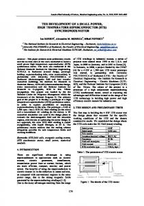
alternative to this, fuzzy logic controller, artificial neural network (ANN) controller, neuro-fuzzy controller and sliding mode controller have been implemented for speed control [4][9]. But these controllers suffer from the drawbacks of either requirement of rule-base, training, chattering problems, increased computations, complexity or inferior performance at steady state, etc. On-line tuning of PI controllers can overcome the problem associated with the fixed gains. Fuzzy logic, genetic algorithm and neural network based tuning algorithms have been reported [10]-[12], but they suffer from intensive computational time and increased complexity. A wavelet transform based multi-resolution proportional plus integral plus derivative (PID) controller has been reported [13]. The application of wavelet transform for drive and a wide variety of applications have been reported and analyzed [13]-[19]. For any signal, the multi-resolution analysis based on wavelet transform provides means of extracting and localizing all frequency components in time present in the analyzed signal [20]. A multi-resolution wavelet (MRW) controller along with an integer order integrator has been used for the speed control of traveling wave ultrasonic motor where the wavelet controller is based on wavelet theory and takes advantage of the advanced filtering capabilities of the wavelet transform [21]. This work can further be extended for other types of motors with additional features in the MRW controller. This paper proposes vector control of PMSM with MRW controller with a fractional order integrator which leads to an increased flexibility and degree of freedom for tuning than the integer order PI controller or the integer order integrator. The other benefits of fractional order controller are that it is better suited for the fractional systems, simplicity, compactness, general structure, added flexibility, etc [22-24]. There is ease of tuning and the control algorithm is simple and computationally far lesser intensive as compared to the MRW controllers with high and low pass filters in cascade. II. VECTOR CONTROL OF PMSM The vector control of PMSM is much similar to that of an induction motor except for the fact that in case of the PMSM, the rotor flux is supplied by the permanent magnets on the rotor [1]. Hence, the reference value of the flux producing component of current is zero. This leads to maximum torque sensitivity for the stator current and minimal inverter rating [1]. Figure 1 shows the schematic diagram for a vector controlled PMSM drive. The control structure consists of an
outer speed loop and two inner current loops. The sensed speed is compared with the demanded value and the resulting error is processed by a speed controller. The speed controller determines the torque necessary to drive the motor to the demanded speed or to maintain the speed. The sensed phase currents undergo co-ordinate transformation so as to be resolved into torque and flux producing components. The reference value for the torque producing component of current is decided by the speed controller, while for flux producing component of current the reference value is zero. The respective reference and actual values of currents are compared and the resulting error is processed by individual current controllers. The current controllers determine the voltage to be impressed across the motor terminals to drive the two current errors to zero. The reference d-q axes voltages undergo inverse transformation to determine the three phase voltages to be impressed across the motor terminals. The reference three phase voltages are fed to a pulse width modulation block, which decides the turn-on and turn-off of the six inverter switches.
sample version of Wf(b,a), sampled in a dyadic grid ie. a = 2 − m and b = n 2 − m , and m , n ∈ Z , Z being the set of positive integers [26]. The discrete wavelet transform can be defined by (2) [26]. ∞
DWTψ f (m, n) =
∫
−∞
f (t )ψ *m ,n ( t ) dt
( 2)
(17)
ψ m , n ( t ) = 2 − mψ ( 2 m t − n )
is the dilated and ψ translate version of the mother wavelet (t ) . Where,
IV. MULTI RESOLUTION WAVELET CONTROLLER The output of the multi-resolution wavelet controller is described in (3) [13], where u(t) is the controller output for error input e(t), which is decomposed in low frequency signal e1(t) with gain K1, and high frequency signals e2(t) – eN(t) with gain K2 – KN, respectively. For appropriate controller performance the controller gains K1 – KN, are to be tuned properly. The number of controller gains depends on the level of decomposition. Also the multi resolution analysis requires high and low pass filters to be cascaded, depending on the decomposition levels greater computational burden and execution time would be imposed.
u (t ) = K1e1 (t ) + K 2 e2 (t ) + K3e3 (t ) + .... + K N eN (t ) (3) Fig. 1. Schematic diagram of the vector controlled PMSM drive
III. WAVELET TRANSFORM A wavelet, in the sense of the discrete wavelet transform, is an orthogonal function which can be applied to a finite group of data [25]. The transform is a convolution and the transforming function is orthogonal, a signal passed twice through the transformation remains unchanged, and the input signal is assumed to be a set of discrete time samples [25]. The wavelet transform decomposes the signal into different scales with different levels of resolution by dilating a single prototype function, the mother wavelet [31]. The continuous wavelet transform of f(t) is given by (1) [26].
For the vector controlled PMSM drive a multi-resolution wavelet speed controller requiring three controller gains for a proportional plus integral plus derivative (PID) controller and two for PI controller operation has been utilized. The discrete wavelet decomposition has the form of transformation using quadrature mirror filters by which a signal sequence x(k) is decomposed into n scales and the results of the decomposition operation is stored in the variable wi shown in (4), where matrices G and H are the low and high pass filter, and signal sequence x is decomposed in n scale [21].
wi = ( Hx, HGx, HG 2 x,… , HG n−1 x, HG n x)
( 4)
The decomposition expressed in (4) can be implemented using a recursive algorithm and with n scale discrete wavelet *⎛ t −b ⎞ CWTψ f ( a , b ) = W f (b , a ) = a ∫−∞ f (t )ψ ⎜⎝ a ⎟⎠ dt (1) transform the input signal into n parts, each one representing a parameter of the dynamics of the signal [21]. The speed error signal is sampled and the sampled data is fed to an Where a , b ∈ R , a ≠ 0 and they are dilating and 1 × N array. For every new sample the data position is shifted translating coefficients, respectively. The asterisk denotes a from the Nth position towards the 0th position, with the oldest 1 − data being discarded and the latest data being in the Nth a 2 complex conjugate. The multiplication factor is for position. As per the mother wavelet, Haar wavelet, the ψ energy normalization purpose. The mother wavelet (t ) is matrices G and H are give by (5) and (6). Application of a three level decomposition wavelet transform for the error scaled by a. The original signal can be completely reconstructed by a input sequence results in (7) [21], where, HG 2 and G 3 are as 1 ∞ − 2
given in (8) and (9), respectively, with f(k) representing the low harmonic component of the input speed error and g(x) expressing the higher harmonic component of the input speed error. 1 [1 1] 2 1 H = [1 − 1] 2 wi = ( Hx , HGx , HG 2 x , G 3 x )
G=
(5) (6) (7)
3
f ( k ) = G x ( k ) = x0 ( k ) + x1 ( k ) + … + x N −1 ( k ) 2
g ( k ) = HG x ( k ) = x 0 ( k ) + x1 ( k ) + … + x( N
2 −1 )
(8) (k )
− … − x N −1 ( k )
(9)
f ( k ) = G 3 x ( k ) = f ( k − 1) − x 0 ( k ) + xin ( k )
(10)
g ( k ) = HG 2 x ( k ) = g ( k ) − x 0 ( k ) − xin ( k ) + 2 x( N
2)
(k ) (11)
An integrator term is added to eliminate the steady state speed error. The resulting multi-resolution PID speed controller is described in (12) [21], where where U(k) is the controller output at the kth sampling instant, and Kp, Ki, Kd are the proportional, integral and differential gains, respectively. The integral term I(k) is defined in (13), where Ts is the sampling time.
U (k ) = K p ⋅ f (k ) + K d ⋅ g (k ) + K i ⋅ I (k ) I ( k ) = I ( k ) + Ts ⋅ xin ( k )
(12 ) (13 )
In motor drive systems, the motor winding inductance suffices the damping requirements, leaving the derivative controller redundant. Also, the derivative controller acts as an amplifier for the noise signals and may lead to increase in noise and ripples in the controller output, leading to increased torque and current ripples. Hence, the PI controller can be suffice the needs of speed controller in a motor drive system and is usually implemented in practice. The multi-resolution wavelet speed controller defined in (14), where the PI controller operation is obtained by neglecting the high frequency term which further simplifies the computations.
U (k ) = K p ⋅ f (k ) + K i ⋅ I (k )
and execution time facilitate the further use of higher sampling and carrier frequency which leads to the reduction in harmonic losses. Figure 2 shows the block diagram of a multi-resolution wavelet speed controller. The commanded and the actual value are compared and the resulting error XIN is fed to the 2dimensional array. The necessary elements of the array are retrieved for the high and low frequency component computations. The low and high frequency component of the input error signal are represented by f(k) and g(k), respectively. These signals as per their gains are scaled and fed to the summer block. One more input to the summer block is the scaled integral of the error input. The output of the summer block represents the multi-resolution wavelet controller output. With the absence of the scaled high frequency signal, the summer output would represent the multi-resolution PI controller output. To incorporate the merits of fractional order controller, multi-resolution wavelet PI speed controller with fractional order integrator, as defined in (15), has been proposed. The factorial order integrator term Ifo(s) is defined in (16), where s is the Laplace operator and 0