Instruments semiconductor products and disclaimers thereto appears at the end
of this data sheet. PRODUCTION DATA information is current as of publication ...
Product Folder
Sample & Buy
Support & Community
Tools & Software
Technical Documents
TPS657051, TPS657052 SLVSA08A – FEBRUARY 2010 – REVISED SEPTEMBER 2015
TPS65705x PMU for Embedded Camera Module 1 Features
3 Description
• • •
The TPS65705x devices are small power management units targeted for embedded camera module or other portable low-power consumer-end equipments. The device contains two highly efficient step-down converters, a low dropout linear regulator, and additional supporting functions. The 2.25-MHz step-down converter enters a low-power mode at light load for maximum efficiency across the widest possible range of load currents. For low-noise applications, the device can be forced into fixedfrequency PWM mode using the MODE pin. The device allows the use of small inductors and capacitors to achieve a small sized solution. The TPS65705x provides an output current of up to 400 mA on both DC-DC converters and integrates one 200-mA LDO with different output settings. The LDO operates with an input voltage range from 1.7 V to 6 V, thus allowing it to be supplied from the output of the step-down converter or directly from the system voltage.
1
• • • • • • • •
Two 400-mA Step-Down Converters Up to 92% Efficiency VIN Range for DC-DC Converter From 3.3 V to 6 V 2.25-MHz Fixed-Frequency Operation Power Save Mode at Light Load Current Output Voltage Accuracy in PWM Mode ±1.5% 100% Duty Cycle for Lowest Dropout 180° Out-of-Phase Operation 1 General Purpose 200-mA LDO VIN Range for LDO From 1.7 V to 6.0 V Available in a 16-Ball DSBGA (WCSP) With 0.5mm Pitch
2 Applications • • •
Digital Cameras Portable Media Players Handheld Equipment
The TPS65705x comes in a small 16-pin wafer chip scale package (WCSP) with 0.5-mm ball pitch. Device Information(1) PART NUMBER
PACKAGE
TPS657051
DSBGA (16)
TPS657052
BODY SIZE (NOM) 2.08 mm × 2.08 mm
(1) For all available packages, see the orderable addendum at the end of the data sheet.
Application Circuit VCC TPS 657051/52 2.2 μH L1
VIN1
10 mF
MODE
DCDC1
EN1
400 mA
FB1
Vout1 10uF
PGND CLK0° 2.25 MHz Oscillator VIN2 EN2
CLK180° L2
2.2 μH Vout2
DCDC2 400 mA
FB2
10 mF
PGND
VLDO
VINLDO ENLDO
LDO 200 mA
Vout3 2.2 mF
AGND
1
An IMPORTANT NOTICE at the end of this data sheet addresses availability, warranty, changes, use in safety-critical applications, intellectual property matters and other important disclaimers. PRODUCTION DATA.
TPS657051, TPS657052 SLVSA08A – FEBRUARY 2010 – REVISED SEPTEMBER 2015
www.ti.com
Table of Contents 1 2 3 4 5 6 7
8
Features .................................................................. Applications ........................................................... Description ............................................................. Revision History..................................................... Device Options....................................................... Pin Configuration and Functions ......................... Specifications.........................................................
1 1 1 2 3 3 4
7.1 7.2 7.3 7.4 7.5 7.6 7.7
4 4 5 5 5 7 7
Absolute Maximum Ratings ...................................... ESD Ratings.............................................................. Recommended Operating Conditions....................... Thermal Information .................................................. Electrical Characteristics........................................... Dissipation Ratings ................................................... Typical Characteristics ..............................................
Detailed Description ............................................ 12 8.1 Overview ................................................................. 12 8.2 Functional Block Diagram ....................................... 12
8.3 Feature Description................................................. 12 8.4 Device Functional Modes........................................ 15
9
Application and Implementation ........................ 16 9.1 Application Information............................................ 16 9.2 Typical Application ................................................. 16
10 Power Supply Recommendations ..................... 18 11 Layout................................................................... 19 11.1 Layout Guidelines ................................................. 19 11.2 Layout Example .................................................... 19
12 Device and Documentation Support ................. 20 12.1 12.2 12.3 12.4 12.5 12.6
Device Support...................................................... Related Links ........................................................ Community Resources.......................................... Trademarks ........................................................... Electrostatic Discharge Caution ............................ Glossary ................................................................
20 20 20 20 20 20
13 Mechanical, Packaging, and Orderable Information ........................................................... 20
4 Revision History NOTE: Page numbers for previous revisions may differ from page numbers in the current version. Changes from Original (February 2010) to Revision A
Page
•
Added ESD Ratings table, Feature Description section, Device Functional Modes, Application and Implementation section, Power Supply Recommendations section, Layout section, Device and Documentation Support section, and Mechanical, Packaging, and Orderable Information section .................................................................................................. 1
•
Changed footnote error for Device Options table................................................................................................................... 3
2
Submit Documentation Feedback
Copyright © 2010–2015, Texas Instruments Incorporated
Product Folder Links: TPS657051 TPS657052
TPS657051, TPS657052 www.ti.com
SLVSA08A – FEBRUARY 2010 – REVISED SEPTEMBER 2015
5 Device Options
(1)
PART NO. (1)
SIZE FOR DSBGA VERSION
OPTIONS
I2C
TPS657051
D = 2076 µm ± 25 µm E = 2076 µm ± 25 µm
DC-DC1 3.3 V FIX, DC-DC2 1.8 V FIX DC-DC CONVERTERS 400 mA, LDO VOUT 3 V FIX, 200 mA
N/A
TPS657052
D = 2076 µm ± 25 µm E = 2076 µm ± 25 µm
DC-DC1 3.3 V FIX, DC-DC2 1.8 V FIX DC-DC CONVERTERS 400 mA, LDO VOUT 2.8 V FIX, 200 mA
N/A
For the most current package and ordering information, see the Mechanical, Packaging, and Orderable Information section at the end of this document, or see the TI website at www.ti.com.
6 Pin Configuration and Functions TPS657051 YZH Package 16-Pin DSBGA Top View 2075um
VLDO
AGND
VIN VIN LDO LDO
VCC
EN1
EN2
VIN2
EN LDO LDO
MODE
L2
VIN1
2075um
A1
B1
L1 C1
PGND PGND 1 D1
FB1
FB2 D2
D3
PGND PGND 2 2 D4
TPS657052 YZH Package 16-Pin DSBGA Top View 2075um
VIN2
VIN VIN LDO LDO
AGND
EN2
EN1
VLDO A1
VIN1 B1
L2
EN EN LDO LDO
MODE
2075um
VCC
L1 C1
PGND PGND 2 2 D4
FB2
FB1 D3
D2
PGND PGND 11 D1
Copyright © 2010–2015, Texas Instruments Incorporated
Product Folder Links: TPS657051 TPS657052
Submit Documentation Feedback
3
TPS657051, TPS657052 SLVSA08A – FEBRUARY 2010 – REVISED SEPTEMBER 2015
www.ti.com
Pin Functions PIN NO.
I/O
NAME
DESCRIPTION
A1
VLDO
O
Output voltage from LDO
A2
AGND
—
Analog ground
A3
VINLDO
I
Input voltage pin for LDO
A4 (1)
VCC
I
Supply Input for internal reference, has to be connected to VIN1/ VIN2
B1 (2)
VIN1
I
Input voltage pin for buck converter 1
B2
EN1
I
Actively high enable input voltage for buck converter 1
B3
EN2
I
Actively high enable input voltage for buck converter 2
B4 (2)
VIN2
I
Input voltage pin for buck converter 2
C1
L1
O
Switch output from buck converter 1
C2
ENLDO
I
Actively high enable input voltage for LDO
C3
MODE
I
Set low to enable Power Save Mode. Pulling this PIN to high forces the device to operate in PWM mode over the whole load range.
C4
L2
O
Switch output from buck converter 2
D1
PGND1
—
Power ground
D2
FB1
I
Feedback input from buck converter 1
D3
FB2
I
Feedback input from buck converter 2
D4
PGND2
—
(1) (2)
Power ground
VCC must be the highest input for the device to function correctly. VIN1/VIN2 must be connected to VCC.
7 Specifications 7.1 Absolute Maximum Ratings over operating free-air temperature range (unless otherwise noted) MIN
MAX
UNIT
Input voltage on all pins except A/PGND pins with respect to AGND
–0.3
7
V
Voltage on pin VLDO1 with respect to AGND
–0.3
3.6
V
L1, VLDO1, VINLDO1, PGND
600
mA
AGND
20
mA
All other pins
3
mA
Current Continuous total power dissipation
See Dissipation Ratings
Operating free-air temperature, TA
–40
Maximum junction temperature, TJ Storage temperature, Tstg
–65
85
°C
125
°C
150
°C
7.2 ESD Ratings VALUE V(ESD) (1) (2)
4
Electrostatic discharge
Human body model (HBM), per ANSI/ESDA/JEDEC JS-001
(1)
Charged device model (CDM), per JEDEC specification JESD22-C101 (2)
±2000 ±500
UNIT V
JEDEC document JEP155 states that 500-V HBM allows safe manufacturing with a standard ESD control process. JEDEC document JEP157 states that 250-V CDM allows safe manufacturing with a standard ESD control process.
Submit Documentation Feedback
Copyright © 2010–2015, Texas Instruments Incorporated
Product Folder Links: TPS657051 TPS657052
TPS657051, TPS657052 www.ti.com
SLVSA08A – FEBRUARY 2010 – REVISED SEPTEMBER 2015
7.3 Recommended Operating Conditions over operating free-air temperature range (unless otherwise noted) MIN
NOM
3.3
MAX
UNIT
VIN1/2
Input voltage for step-down converter DCDC1 and DCDC2
IOUTDCDC1/2
Output current at L
6
L
Inductor at L
1.5
VINLDO
Input voltage for LDO
1.7
ILDO
Output current at LDO
CINDCDC1/2
Input Capacitor at VIN1 and VIN2
4.7
COUTDCDC1/2
Output Capacitor at VOUT1, VOUT2
4.7
CINLDO
Input Capacitor at VINLDO
2.2
COUTLDO
Output Capacitor at VLDO
2.2
TA
Operating ambient temperature
–40
85
°C
TJ
Operating junction temperature
–40
125
°C
2.2
V
400
mA
4.7
µH
6.0
V
200
mA µF
10
22
µF µF µF
7.4 Thermal Information TPS65705x THERMAL METRIC
(1)
YZH (DSBGA)
UNIT
16 PINS RθJA
Junction-to-ambient thermal resistance
75
°C/W
RθJC(top)
Junction-to-case (top) thermal resistance
22
°C/W
RθJB
Junction-to-board thermal resistance
26
°C/W
ψJT
Junction-to-top characterization parameter
0.2
°C/W
ψJB
Junction-to-board characterization parameter
24
°C/W
RθJC(bot)
Junction-to-case (bottom) thermal resistance
N/A
°C/W
(1)
For more information about traditional and new thermal metrics, see the Semiconductor and IC Package Thermal Metrics application report, SPRA953.
7.5 Electrical Characteristics Unless otherwise noted: VIN1 = VIN2 = VINLDO = 3.6 V, L = LQMP21P 2.2 µH, COUTDCDCx = 10 µF, COUTLDO = 2.2 µF, TA = –40°C to +85°C PARAMETER
TEST CONDITIONS
MIN
TYP
MAX
UNIT
SUPPLY CURRENT DCDC1 and DCDC2 enabled, IOUT = 0 mA, MODE =0 (PFM mode), LDO disabled
40
µA
DCDC1 or DCDC2 enabled, IOUT = 0 mA, MODE =0 (PFM mode), LDO disabled
25
µA
DCDC1 or DCDC2 enabled, IOUT = 0 mA. MODE =1 (forced PWM mode), LDO disabled
4
mA
Operating quiescent current LDO
DCDC1 and DCDC2 disabled, LDO enabled. IOUT = 0 mA
25
37
µA
Shutdown current
DCDC1, DCDC2, and LDO disable
5
12
µA
VCC
V
0.4
V
0.1
μA
6
V
Operating quiescent current DCDCx IQ
ISD
DIGITAL PINS (EN1, EN2, ENLDO, MODE) VIH
High-level input voltage for EN1, EN2, ENLDO, MODE
VIL
Low-level input voltage for EN1, EN2, ENLDO, MODE
ILKG
Input leakage current
1.2
EN1, EN2, ENLDO, MODE tied to GND or VIN = VIN2
0.01
STEP-DOWN CONVERTERS VIN1
Input voltage for DCDC1
3.3
Copyright © 2010–2015, Texas Instruments Incorporated
Product Folder Links: TPS657051 TPS657052
Submit Documentation Feedback
5
TPS657051, TPS657052 SLVSA08A – FEBRUARY 2010 – REVISED SEPTEMBER 2015
www.ti.com
Electrical Characteristics (continued) Unless otherwise noted: VIN1 = VIN2 = VINLDO = 3.6 V, L = LQMP21P 2.2 µH, COUTDCDCx = 10 µF, COUTLDO = 2.2 µF, TA = –40°C to +85°C PARAMETER VIN2
TEST CONDITIONS
MIN
Input voltage for DCDC2
TYP
3.3
MAX
UNIT
6
V
2.25
V
Internal undervoltage lockout threshold
VIN1 = VIN2 falling
Internal undervoltage lockout threshold hysteresis
VIN1 = VIN2 rising
120
High-side MOSFET ON-resistance
VIN1 = VIN2 = 3.6 V
350
750
mΩ
Low-side MOSFET ON-resistance
VIN1 = VIN2 = 3.6 V
350
600
mΩ
ILIMF
Forward current limit
3.3 V ≤ VIN1 = VIN2 ≤ 6 V
650
770
mA
IOUTDCDC1/2
DCDC1/DCDC2 output current
VIN1 = VIN2 > 3.3 V , L = 2.2 µH
400
mA
2.48
MHz
UVLO
2.15
2.2
mV
POWER SWITCH RDS(ON)
550
OSCILLATOR fSW
Oscillator frequency
2.03
2.25
OUTPUT VOUT1
DCDC1 default output voltage
VIN1 = VIN2 ≥ 3.3 V
3.3
V
VOUT2
DCDC2 default output voltage
VIN1 = VIN2 ≥ 3.3 V
1.8
V
IFB
FB pin input current
DC-DC converter disabled
DC output voltage accuracy (1)
VIN1 = VIN2 = 3.3 V to 6 V, +1% voltage positioning active; PFM operation, 0 mA < IOUT < IOUTMAX
DC output voltage accuracy
VIN1 = VIN2 = 3.3 V to 6 V, PWM operation, 0 mA < IOUT < IOUTMAX
DC output voltage load regulation
PWM operation
0.5
%/A
tStart
Start-up time
Time from active EN to Start switching
200
µs
tRamp
VOUT ramp time
Time to ramp from 5% to 95% of VOUT
250
µs
RDIS
Internal discharge resistor at L1 or L2 (TPS657051 Only)
DCDC1 or DCDC2 disabled
VOUT
0.1 +1% –1.5%
250
µA
+3% +1.5%
400
600
Ω
THERMAL PROTECTION SEPARATELY FOR DCDC1, DCDC2 AND LDO1 TSD
Thermal shutdown
Increasing junction temperature
150
°C
Thermal shudown hysteresis
Decreasing junction temperature
30
°C
VLDO, LOW DROPOUT REGULATOR VINLDO
Input voltage range for LDO
VLDO
TPS657051 LDO default output voltage (2)
3
V
VLDO
TPS657052 LDO default output voltage (3)
2.8
V
IO
Output current for LDO
ISC
LDO short circuit current limit
VLDO = GND
Dropout voltage at LDO
IO = 200 mA
Output voltage accuracy for LDO
IO = 100 mA, VOUT = 2.8V
–2%
+2%
Line regulation for LDO
VINLDO = VLDO + 0.5 V (min. 1.7 V) to 6 V, IO = 50 mA
–1%
1%
Load regulation for LDO
IO = 1 mA to 200 mA for LDO
–1%
1%
PSRR
Power supply rejection ratio
fNOISE ≤ 10 kHz, COUT ≥ 2.2 µf Vin = 5 V, Vout = 2.8 V, IOUT = 100 mA
Vn
Ouput noise voltage
Vout = 2.8 V, BW = 10Hz to 100kHz
(1) (2) (3) 6
1.7
340
6
400
V
200
mA
550
mA
200
mV
50
dB
160
µV RMS
In Power Save Mode (PFM), the internal reference voltage is 1.01 × Vref. VINLDO > 3 V VINLDO > 2.8 V Submit Documentation Feedback
Copyright © 2010–2015, Texas Instruments Incorporated
Product Folder Links: TPS657051 TPS657052
TPS657051, TPS657052 www.ti.com
SLVSA08A – FEBRUARY 2010 – REVISED SEPTEMBER 2015
Electrical Characteristics (continued) Unless otherwise noted: VIN1 = VIN2 = VINLDO = 3.6 V, L = LQMP21P 2.2 µH, COUTDCDCx = 10 µF, COUTLDO = 2.2 µF, TA = –40°C to +85°C PARAMETER
TEST CONDITIONS
MIN
tRamp
VOUT ramp time
Internal soft-start when LDO is enabled; Time to ramp from 5% to 95% of VOUT
RDIS
Internal discharge resistor at VLDO
LDO disabled
TYP
MAX
UNIT
200 250
400
µs 550
Ω
7.6 Dissipation Ratings PACKAGE
RθJA
TA ≤ 25°C POWER RATING
DERATING FACTOR ABOVE TA = 25°C
TA = 70°C POWER RATING
TA = 85°C POWER RATING
TPS657051/52 (1)
YZH
185
540 mW
5.4 mW
297 mW
216 mW
(2)
YZH
75
1.3 W
13.3 mW
0.7 W
0.5 W
DEVICE
TPS657051/52 (1) (2)
The JEDEC low-K (1s) board used to derive this data was a 3in × 3in, two-layer board with 2-ounce copper traces on top of the board. The JEDEC high-K (2s2p) board used to derive this data was a 3in × 3in, multilayer board with 1-ounce internal power and ground.
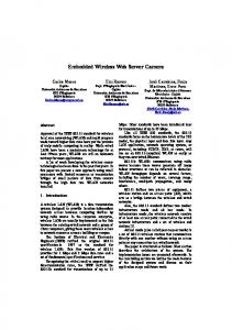
7.7 Typical Characteristics Table 1. Table Of Graphs FIGURE Efficiency DC-DC (VDCDC= 3.3 V), L = BRC1608 1.5 µH
vs Load current / PFM mode
Figure 1
Efficiency DC-DC (VDCDC= 3.3 V), L = BRC1608 1.5 µH
vs Load current / PWM mode
Figure 2
Efficiency DC-DC (VDCDC= 1.8 V), L = BRC1608 1.5 µH
vs Load current / PFM mode
Figure 3
Efficiency DC-DC (VDCDC= 1.8 V), L = BRC1608 1.5 µH
vs Load current / PWM mode
Figure 4
Line transient response DC-DC 1.8 V (PWM)
Scope plot
Figure 5
Line transient response DC-DC 1.8 V (PFM)
Scope plot
Figure 6
Line transient response LDO 2.8 V
Scope plot
Figure 7
Load transient response DC-DC 1.8 V (PWM/PFM) 20 mA to 180 mA
Scope plot
Figure 8
Load transient response DC-DC 1.8 V (PWM) 20 mA to 180 mA
Scope plot
Figure 9
Load transient response DC-DC 1.8 V (PFM/PWM) 20 mA to 360 mA
Scope plot
Figure 10
Load transient response DC-DC 1.8 V (PWM) 20 mA to 360 mA
Scope plot
Figure 11
Load transient response LDO 2.8 V
Scope plot
Figure 12
DC-DC PFM to PWM mode transition
Scope plot
Figure 13
DC-DC PWM to PFM mode transition
Scope plot
Figure 14
DC-DC Output voltage ripple in PFM mode
Scope plot
Figure 15
DC-DC Output voltage ripple in PWM mode
Scope plot
Figure 16
Startup timing DC-DC 1.8 V
Scope plot
Figure 22
Startup timing LDO 2.8 V
Scope plot
Figure 23
LDO PSRR
Scope plot
Figure 17
DC-DC Quiescent current
vs VINDCDC
Figure 18
LDO Quiescent current
vs VINDCDC
Figure 19
Shutdown current
vs VINDCDC
Figure 20
Copyright © 2010–2015, Texas Instruments Incorporated
Product Folder Links: TPS657051 TPS657052
Submit Documentation Feedback
7
TPS657051, TPS657052 www.ti.com
100
100
90
90
80
80
70
70
Efficiency - %
Efficiency - %
SLVSA08A – FEBRUARY 2010 – REVISED SEPTEMBER 2015
60 3.5 3.6 3.8 4.0 4.2 4.5 4.8 5.0 5.5 6.0
50 40 30 20 10
VOUT = 3.3 V, TA = 25°C L = BRC1608 1.5μA
0 0.001
0.01 0.1 IO - Output Current - A
50 40
10 0 0.001
1
90
80
80
70
70
Efficiency - %
90
60 2.5 3.0 3.5 4.0 4.5 5.0 5.5 6.0
30 20 10
VOUT = 1.8 V, TA = 25°C L = BRC1608 1.5μA
0 0.001
0.01 0.1 IO - Output Current - A
0.01 0.1 IO - Output Current - A
VOUT = 1.8 V, TA = 25°C L = BRC1608 1.5 μA
60 50
2.5 3.0 3.5 4.0 4.5 5.0 5.5 6.0
40 30 20 10 0 0.001
1
Figure 3. Efficiency DC-DC (VDCDC=1.8 V) vs Load Current PFM mode
1
Figure 2. Efficiency DC-DC (VDCDC=3.3 V) vs Load Current PWM Mode 100
40
VOUT = 3.3 V, TA = 25°C L = BRC1608 1.5μA
20
100
50
3.5 3.6 3.8 4.0 4.2 4.5 4.8 5.0 5.2 5.5 6.0
30
Figure 1. Efficiency DC-DC (VDCDC=3.3 V) vs Load Current PFM Mode
Efficiency - %
60
0.01 0.1 IO - Output Current - A
1
Figure 4. Efficiency DC-DC (VDCDC=1.8 V) vs Load Current PWM mode
VINDCDC = 3.6V to 4.2V to 3.6V Temperature = 25°C
VINDCDC
DCDC Load Current = 200mA VDCDC = 1.8V Mode = VINDCDC
VINDCDC = 3.6V to 4.2V to 3.6V Temperature = 25°C VINDCDC
VDCDC
VDCDC
DCDC Load Current = 75mA VDCDC = 1.8V Mode = GND
DCDC Load
DCDC Load
Time - 100 ms/div
Time - 100 ms/div
Figure 5. Line Transient Response DC-DC 1.8 V (PWM)
8
Submit Documentation Feedback
Figure 6. Line Transient Response DC-DC 1.8 V (PFM)
Copyright © 2010–2015, Texas Instruments Incorporated
Product Folder Links: TPS657051 TPS657052
TPS657051, TPS657052 www.ti.com
SLVSA08A – FEBRUARY 2010 – REVISED SEPTEMBER 2015
VINDCDC = 5.0V Temperature = 25°C
VINDCDC = 5.0V VINLDO = 3.6V to 4.2V to 3.6V Temperature = 25°C
DCDC Load Current = 20mA to 180mA VDCDC = 1.8V Mode = GND
VINLDO
LDO Load Current = 200mA VLDO = 2.8V VLDO
VDCDC
LDO Load
DCDC Load Current
Time - 100 ms/div
Time - 100 ms/div
Figure 7. Line Transient Response LDO 2.8 V
Figure 8. Load Transient Response DC-DC 1.8 V (PWM/PFM) 20 mA to 180 mA
VINDCDC = 5.0V Temperature = 25°C
VINDCDC = 5.0V Temperature = 25°C
DCDC Load Current = 20mA to 360mA VDCDC = 1.8V Mode = GND VDCDC
DCDC Load Current = 20mA to 180mA VDCDC = 1.8V Mode = VINDCDC
VDCDC
DCDC Load Current DCDC Load Current
Time - 100 ms/div
Time - 100 ms/div
Figure 9. Load Transient Response DC-DC 1.8 V (PWM) 20 mA to 180 mA
VINDCDC = 5.0V Temperature = 25°C
Figure 10. Load Transient Response DC-DC 1.8 V (PFM/PWM) 20 mA to 360 mA VINDCDC = 5 V, VINLDO = 5 V Temperature = 25°C LDO Load Current = 20 mA to 180 mA VLDO VINDCDC = 5.0 V VINLDO = 5.0 V Temperature = 25°C
VDCDC
DCDC Load Current = 20mA to 360mA VDCDC = 1.8V Mode = VINDCDC
LDO Load Current = 20mA to 180mA VLDO = 2.8V VLDO = 2.8 V LDO Load Current
DCDC Load Current
Time - 100 ms/div
Time - 100 ms/div
Figure 11. Load Transient Response DC-DC 1.8 V (PWM) 20 mA to 360 mA
Figure 12. Load Transient Response LDO
Copyright © 2010–2015, Texas Instruments Incorporated
Product Folder Links: TPS657051 TPS657052
Submit Documentation Feedback
9
TPS657051, TPS657052 SLVSA08A – FEBRUARY 2010 – REVISED SEPTEMBER 2015
Mode
www.ti.com
VINDCDC = 5.0V Temperature = 25°C
VDCDC
DCDC Load Current = 10mA VDCDC = 1.8V Mode = GND to VINDCDC
VINDCDC = 5.0V Temperature = 25°C
Mode VDCDC
SW
SW
DCDC Load Current = 10mA VDCDC = 1.8V Mode = VINDCDC to GND
DCDC Inductor Current
DCDC Inductor Current
Time - 10 ms/div
Time - 10 ms/div
Figure 13. DC-DC PFM to PWM Mode Transition
Figure 14. DC-DC PWM to PFM Mode Transition
VINDCDC = 5.0V Temperature = 25°C
VINDCDC = 5.0V Temperature = 25°C DCDC Output
DCDC Load Current = 200mA VDCDC = 1.8V Mode = GND
DCDC Load Current = 60mA VDCDC = 1.8V Mode = GND
DCDC Output
SW
SW
DCDC Inductor Current
DCDC Inductor Current
Time - 2 ms/div
Time - 1 ms/div
Figure 15. DC-DC Output Voltage Ripple in PFM Mode
Figure 16. DC-DC Output Voltage Ripple in PWM Mode 60
100
Rejection Ratio - dB
80
50
Quiescent Current - μA
90
LDO VO = 2.8 V, Load = 100 mA, VI = 5 V PSRR
70 60 IO = 100 mA 50 40 30 20
Vout = 1.2V, Mode = GND ENDCDC1 = VINDCDC, no load ENDCDC2 = GND ENLDO = GND 25°C 85°C
-40°C
40
30
20
10
10 0 10
100
1k 10k 100k f - Frequency - Hz
Figure 17. LDO PSRR
10
Submit Documentation Feedback
1M
10M
0 2.5
3
3.5 4 4.5 5 VCC - Supply Voltage - V
5.5
6
Figure 18. DC-DC Quiescent Current
Copyright © 2010–2015, Texas Instruments Incorporated
Product Folder Links: TPS657051 TPS657052
TPS657051, TPS657052 www.ti.com
SLVSA08A – FEBRUARY 2010 – REVISED SEPTEMBER 2015 30
100
Quiescent Current - μA
80 70
Vout = 1.2V Mode = GND ENDCDC1 = GND ENDCDC2 = GND ENLDO =VINDCDC, no load
25
Shutdown Current - μA
90
60 50
85°C 25°C
40 30 20
Vout = 1.2V Mode = GND ENDCDC1 = GND ENDCDC2 = GND ENLDO = GND
20 85°C
25°C
-40°C
15
10
5
-40°C 10 0 2.92
3.42
3.92 4.42 4.92 5.42 VCC - Supply Voltage - V
Figure 19. LDO Quiescent Current
5.92
0 2.5
3
3.5 4 4.5 5 VCC - Supply Voltage - V
5.5
6
Figure 20. Shutdown Current
Copyright © 2010–2015, Texas Instruments Incorporated
Product Folder Links: TPS657051 TPS657052
Submit Documentation Feedback
11
TPS657051, TPS657052 SLVSA08A – FEBRUARY 2010 – REVISED SEPTEMBER 2015
www.ti.com
8 Detailed Description 8.1 Overview The TPS65705x integrates fixed-output voltage, two highly efficient step-down converters, along with an LDO. Each regulator has dedicated input pins for easy control.
8.2 Functional Block Diagram
VCC TPS657051/52
VIN1
2. 2 mH L1 Vout1
MODE
DCDC1
EN1
400 mA
10 mF
FB 1
10 mF
PGND CLK 0° 2 .25 MHz Oscillator CLK 180 ° L2
2. 2 mH
VIN2 EN2
Vout2 DCDC2 400 mA FB 2
10 mF
PGND
VLDO
VINLDO ENLDO
Vout3 2 .2 mF
LDO 200 mA
AGND
8.3 Feature Description 8.3.1 DC-DC Converter The TPS65705x step-down converter operates with typically 2.25-MHz fixed-frequency pulse width modulation (PWM) at moderate to heavy load currents. With MODE pin set to low, at light load currents the converter can automatically enter Power Save Mode and operates then in PFM mode. During PWM operation the converter use a unique fast response voltage mode control scheme with input voltage feed-forward to achieve good line and load regulation allowing the use of small ceramic input and output capacitors. At the beginning of each clock cycle initiated by the clock signal, the high-side MOSFET switch is turned on. The current flows now from the input capacitor through the high-side MOSFET switch through the inductor to the output capacitor and load. During this phase, the current ramps up until the PWM comparator trips
12
Submit Documentation Feedback
Copyright © 2010–2015, Texas Instruments Incorporated
Product Folder Links: TPS657051 TPS657052
TPS657051, TPS657052 www.ti.com
SLVSA08A – FEBRUARY 2010 – REVISED SEPTEMBER 2015
Feature Description (continued) and the control logic will turn off the switch. The current limit comparator will also turn off the switch in case the current limit of the high-side MOSFET switch is exceeded. After an off time preventing shoot through current, the low-side MOSFET rectifier is turned on and the inductor current will ramp down. The current flows now from the inductor to the output capacitor and to the load. It returns back to the inductor through the low-side MOSFET rectifier. The next cycle will be initiated by the clock signal again turning off the low-side MOSFET rectifier and turning on the on the high-side MOSFET switch. The DCDC1 converter output voltage is set to 3.3 V and the DCDC2 converter output voltage is set to 1.8 V per default. A 180° phase shift between DCDC1 and DCDC2 decreases the input RMS current and synchronizes the operation of the two DC-DC converts. The FB pin must be directly connected to the output voltage of DC-DC and no external resistor network must be connected. 8.3.2 Power Save Mode The Power Save Mode is enabled with Mode Pin set to low. If the load current decreases, the converter will enter Power Save Mode operation automatically. During Power Save Mode the converter skips switching and operates with reduced frequency in PFM mode with a minimum quiescent current to maintain high efficiency. The converter will position the output voltage typically +1% above the nominal output voltage. This voltage positioning feature minimizes voltage drops caused by a sudden load step. The transition from PWM mode to PFM mode occurs once the inductor current in the low-side MOSFET switch becomes zero, which indicates discontinuous conduction mode. During the Power Save Mode the output voltage is monitored with a PFM comparator. As the output voltage falls below the PFM comparator threshold of VOUT nominal +1%, the device starts a PFM current pulse. The high-side MOSFET switch will turn on, and the inductor current ramps up. After the ON-time expires, the switch is turned off and the low-side MOSFET switch is turned on until the inductor current becomes zero. The converter effectively delivers a current to the output capacitor and the load. If the load is below the delivered current, the output voltage will rise. If the output voltage is equal or higher than the PFM comparator threshold, the device stops switching and enters a sleep mode with typical 25-µA current consumption. If the output voltage is still below the PFM comparator threshold, a sequence of further PFM current pulses are generated until the PFM comparator threshold is reached. The converter starts switching again once the output voltage drops below the PFM comparator threshold. With a fast single threshold comparator, the output voltage ripple during PFM mode operation can be kept small. The PFM Pulse is time controlled, which allows to modify the charge transferred to the output capacitor by the value of the inductor. The resulting PFM output voltage ripple and PFM frequency depend in first order on the size of the output capacitor and the inductor value. Increasing output capacitor values and inductor values will minimize the output ripple. The PFM frequency decreases with smaller inductor values and increases with larger values. The PFM mode is left and PWM mode is entered in case the output current can not longer be supported in PFM mode. The Power Save Mode can be disabled by setting Mode pin to high. The converter will then operate in fixed-frequency PWM mode. 8.3.2.1 Dynamic Voltage Positioning This feature reduces the voltage under/overshoots at load steps from light to heavy load and vice versa. It is active in Power Save Mode and regulates the output voltage 1% higher than the nominal value. This provides more headroom for both the voltage drop at a load step, and the voltage increase at a load throw-off.
Copyright © 2010–2015, Texas Instruments Incorporated
Product Folder Links: TPS657051 TPS657052
Submit Documentation Feedback
13
TPS657051, TPS657052 SLVSA08A – FEBRUARY 2010 – REVISED SEPTEMBER 2015
www.ti.com
Feature Description (continued) 8.3.2.2 Soft Start The step-down converter in TPS657051/52 has an internal soft start circuit that controls the ramp up of the output voltage. The output voltage ramps up from 5% to 95% of its nominal value within typical 250s. This limits the inrush current in the converter during ramp up and prevents possible input voltage drops when a battery or high impedance power source is used.
EN 95%
5% VOUT tStart
tRAMP
Figure 21. Soft Start 8.3.2.3 100% Duty Cycle Low Dropout Operation The device starts to enter 100% duty cycle mode once the input voltage comes close to the nominal output voltage. In order to maintain the output voltage, the high-side MOSFET switch is turned on 100% for one or more cycles. With further decreasing VIN the high-side MOSFET switch is turned on completely. In this case the converter offers a low input-to-output voltage difference. This is particularly useful in battery-powered applications to achieve longest operation time by taking full advantage of the whole battery voltage range. The minimum input voltage to maintain regulation depends on the load current and output voltage, and can be calculated as: VINmin = VOmax + IOmax (RDS(on)max + RL)
where • • • •
IOmax = maximum output current plus inductor ripple current RDS(on)max = maximum high-side switch RDSon RL = DC resistance of the inductor VOmax = nominal output voltage plus maximum output voltage tolerance
(1)
8.3.3 180° Out-of-Phase Operation In PWM Mode the converters operate with a 180° turn-on phase shift of the PMOS (high-side) transistors. This prevents the high-side switches of both converters from being turned on simultaneously, and therefore smooths the input current. This feature reduces the surge current drawn from the supply. 8.3.3.1 Under-Voltage Lockout The under voltage lockout circuit prevents the device from malfunctioning at low input voltages and from excessive discharge of the battery and disables the converters and LDOs. The under-voltage lockout threshold is typically 2.2 V. 8.3.4 Short-Circuit Protection All outputs are short-circuit protected with a maximum output current as defined in the electrical specifications. 8.3.5 Thermal Shutdown As soon as the junction temperature, TJ, exceeds typically 150°C for the DC-DC converter or LDO, the device goes into thermal shutdown. In this mode, the low-side and high-side MOSFETs are turned-off. The device continues its operation when the junction temperature falls below the thermal shutdown hysteresis again. A thermal shutdown for the LDO or the DC-DC converter will disable both power supplies simultaneously. 14
Submit Documentation Feedback
Copyright © 2010–2015, Texas Instruments Incorporated
Product Folder Links: TPS657051 TPS657052
TPS657051, TPS657052 www.ti.com
SLVSA08A – FEBRUARY 2010 – REVISED SEPTEMBER 2015
Feature Description (continued) 8.3.6 LDO The low dropout voltage regulator is designed to operate well with low value ceramic input and output capacitors. It operates with input voltages down to 1.7 V. The LDO offers a maximum dropout voltage of 200 mV at rated output current. The LDO supports a current limit feature. 8.3.7 Enable for DCDC1, DCDC2 and LDO Disabling the DC-DC converter or LDO, forces the device into shutdown, with a shutdown quiescent current as defined in Electrical Characteristics. In this mode, the power FETs are turned-off and the entire internal control circuitry is switched-off.
8.4 Device Functional Modes DCDC1, DCDC2, and LDO have dedicated enable pins. If all enable pins are pulled low the device will remain shutdown. If any of enable pins are pulled high corresponding regulators are enabled.
Copyright © 2010–2015, Texas Instruments Incorporated
Product Folder Links: TPS657051 TPS657052
Submit Documentation Feedback
15
TPS657051, TPS657052 SLVSA08A – FEBRUARY 2010 – REVISED SEPTEMBER 2015
www.ti.com
9 Application and Implementation NOTE Information in the following applications sections is not part of the TI component specification, and TI does not warrant its accuracy or completeness. TI’s customers are responsible for determining suitability of components for their purposes. Customers should validate and test their design implementation to confirm system functionality.
9.1 Application Information The TPS65705x device is designed for use as a power supply for embedded camera modules or other portable low-power equipment.
9.2 Typical Application VCC TPS 657051/52 2.2 μH L1
VIN1
10 mF
MODE
DCDC1
EN1
400 mA
FB1
Vout1 10uF
PGND CLK0° 2.25 MHz Oscillator VIN2 EN2
CLK180° L2
2.2 μH Vout2
DCDC2 400 mA
FB2
10 mF
PGND
VLDO
VINLDO ENLDO
Vout3 2.2 mF
LDO 200 mA
AGND
9.2.1 Design Requirements For this design example, use the parameters listed in Table 2 as the input parameters. Table 2. Design Parameters DESIGN PARAMETER
VALUE
Input Supply Voltage
3.3 V to 6 V
Switching Frequency
2.25 Mhz
9.2.2 Detailed Design Procedure 9.2.2.1 Output Filter Design (Inductor and Output Capacitor) 9.2.2.1.1 Inductor Selection
The converter operates typically with 2.2-µH output inductor. Larger or smaller inductor values can be used to optimize the performance of the device for specific operation conditions. The selected inductor has to be rated for its DC resistance and saturation current. The DC resistance of the inductor will influence directly the efficiency of the converter. Therefore an inductor with lowest DC resistance should be selected for highest efficiency. Equation 2 calculates the maximum inductor current under static load conditions. The saturation current of the inductor should be rated higher than the maximum inductor current as calculated with Equation 2. This is recommended because during heavy load transient the inductor current will rise above the calculated value.
16
Submit Documentation Feedback
Copyright © 2010–2015, Texas Instruments Incorporated
Product Folder Links: TPS657051 TPS657052
TPS657051, TPS657052 www.ti.com
SLVSA08A – FEBRUARY 2010 – REVISED SEPTEMBER 2015
Vout Vin L ´ ¦
1ΔIL = Vout ´
ILmax =Ioutmax +
(2)
DIL 2
where • • • •
f = Switching Frequency (2.25 MHz typical) L = Inductor Value ΔIL = Peak-to-Peak inductor ripple current ILmax = Maximum Inductor current
(3)
The highest inductor current will occur at maximum Vin. Open core inductors have a soft saturation characteristic and they can usually handle higher inductor currents versus a comparable shielded inductor. A more conservative approach is to select the inductor current rating just for the maximum switch current of the corresponding converter. It must be considered, that the core material from inductor to inductor differs and will have an impact on the efficiency especially at high switching frequencies. Notice that the step-down converter has internal loop compensation. As the internal loop compensation is designed to work with a certain output filter corner frequency calculated as follows: 1 ¦c = with L = 2.2 m H, Cout = 10 m F 2 p L ´ Cout (4) This leads to the fact the selection of external L-C filter has to be coped with the above formula. As a general rule of thumb the product of LxCout should be constant while selecting smaller inductor or increasing output capacitor value. Refer to Table 3 and the typical applications for possible inductors. Table 3. Tested Inductors INDUCTOR TYPE
INDUCTOR VALUE
SUPPLIER
BRC1608
1.5 µH
Taiyo Yuden
MLP2012
2.2 µH
TDK
MIPSA2520
2.2 µH
FDK
LPS3015
2.2 µH
Coilcraft
LQM21P
2.2 µH
Murata
9.2.2.1.2 Output Capacitor Selection
The advanced Fast Response voltage mode control scheme of the step-down converter allows the use of small ceramic capacitors with a typical value of 10 µF, without having large output voltage under and overshoots during heavy load transients. Ceramic capacitors having low ESR values result in lowest output voltage ripple and are therefore recommended. For an inductor value of 2.2 µH, an output capacitor with 10 µF can be used. Refer to Table 4. If ceramic output capacitors are used, the capacitor RMS ripple current rating will always meet the application requirements. Just for completeness the RMS ripple current is calculated as: Vout 11 Vin ´ IRMSCout = Vout ´ L ´ ¦ 2 ´ 3 (5) At nominal load current the inductive converters operate in PWM mode and the overall output voltage ripple is the sum of the voltage spike caused by the output capacitor ESR plus the voltage ripple caused by charging and discharging the output capacitor:
Copyright © 2010–2015, Texas Instruments Incorporated
Product Folder Links: TPS657051 TPS657052
Submit Documentation Feedback
17
TPS657051, TPS657052 SLVSA08A – FEBRUARY 2010 – REVISED SEPTEMBER 2015
www.ti.com
Vout ö 1 Vin ´ æ + ESR ÷ ç L ´ ¦ è 8 ´ Cout ´ ¦ ø
1DVout = Vout ´
(6)
Where the highest output voltage ripple occurs at the highest input voltage Vin. At light load currents the converter operates in Power Save Mode and the output voltage ripple is dependent on the output capacitor value. The output voltage ripple is set by the internal comparator delay and the external capacitor. The typical output voltage ripple is less than 1% of the nominal output voltage 9.2.2.1.3 Input Capacitor Selection
Because of the nature of the buck converter having a pulsating input current, a low ESR input capacitor is required for best input voltage filtering and minimizing the interference with other circuits caused by high input voltage spikes. The converters need a ceramic input capacitor of 10 µF. The input capacitor can be increased without any limit for better input voltage filtering. Table 4. Tested Capacitors TYPE
COMPONENT SUPPLIER
VALUE
VOLTAGE RATING
SIZE
MATERIAL
DC-DC Output Capacitor
Murata GRM155R60G475ME47D
4.7 µF
4V
0402
Ceramic X5R
LDO I/O Capacitor
Murata GRM155R60J225ME15D
2.2 µF
6.3 V
0402
Ceramic X5R
DC-DC Output Capacitor
Murata GRM188R60J475K
4.7 µF
6.3 V
0603
Ceramic X5R
DC-DC I/O Capacitor
Murata GRM188R60J106M69D
10 µF
6.3 V
0603
Ceramic X5R
9.2.3 Application Curves
VINDCDC = 5.0V Temperature = 25°C VDCDC = 1.8V EN
EN
VDCDC
VINDCDC = 5.0V VINLDO = 5.0V Temperature = 25°C
VLDO
VLDO = 2.8V SW LDO Input Current
DCDC Input Current
Time - 80 ms/div
Time - 80 ms/div
Figure 22. Start-Up Timing DC-DC
Figure 23. Start-Up Timing LDO
10 Power Supply Recommendations The device is optimized to be powered from single-cell Lithium battery. The input supply is required to stay above UVLO threshold without shutting down DC-DC converters. Power input pins of each regulator should be properly bypassed through ceramic capacitors that work best when placed close to the input pins as close as possible.
18
Submit Documentation Feedback
Copyright © 2010–2015, Texas Instruments Incorporated
Product Folder Links: TPS657051 TPS657052
TPS657051, TPS657052 www.ti.com
SLVSA08A – FEBRUARY 2010 – REVISED SEPTEMBER 2015
11 Layout 11.1 Layout Guidelines • • •
All input capacitors should be soldered as close as possible to the device. All inductors should be placed as close as possible to switching pins through thick trace. All feedback traces should be routed differentially and away from noisy traces such as switching signals.
11.2 Layout Example
VLDO
VINLDO
GND GND VIN1 VIN2
L1
L2
GND
Place input capacitors close to VINx pins
Place inductors close to Lx pins GND Run feedback traces differentially
GND
FB1
FB2 VOUT1
VOUT2
Figure 24. Layout Recommendation
Copyright © 2010–2015, Texas Instruments Incorporated
Product Folder Links: TPS657051 TPS657052
Submit Documentation Feedback
19
TPS657051, TPS657052 SLVSA08A – FEBRUARY 2010 – REVISED SEPTEMBER 2015
www.ti.com
12 Device and Documentation Support 12.1 Device Support 12.1.1 Third-Party Products Disclaimer TI'S PUBLICATION OF INFORMATION REGARDING THIRD-PARTY PRODUCTS OR SERVICES DOES NOT CONSTITUTE AN ENDORSEMENT REGARDING THE SUITABILITY OF SUCH PRODUCTS OR SERVICES OR A WARRANTY, REPRESENTATION OR ENDORSEMENT OF SUCH PRODUCTS OR SERVICES, EITHER ALONE OR IN COMBINATION WITH ANY TI PRODUCT OR SERVICE.
12.2 Related Links The table below lists quick access links. Categories include technical documents, support and community resources, tools and software, and quick access to sample or buy. Table 5. Related Links PARTS
PRODUCT FOLDER
SAMPLE & BUY
TECHNICAL DOCUMENTS
TOOLS & SOFTWARE
SUPPORT & COMMUNITY
TPS657051
Click here
Click here
Click here
Click here
Click here
TPS657052
Click here
Click here
Click here
Click here
Click here
12.3 Community Resources The following links connect to TI community resources. Linked contents are provided "AS IS" by the respective contributors. They do not constitute TI specifications and do not necessarily reflect TI's views; see TI's Terms of Use. TI E2E™ Online Community TI's Engineer-to-Engineer (E2E) Community. Created to foster collaboration among engineers. At e2e.ti.com, you can ask questions, share knowledge, explore ideas and help solve problems with fellow engineers. Design Support TI's Design Support Quickly find helpful E2E forums along with design support tools and contact information for technical support.
12.4 Trademarks E2E is a trademark of Texas Instruments. All other trademarks are the property of their respective owners.
12.5 Electrostatic Discharge Caution These devices have limited built-in ESD protection. The leads should be shorted together or the device placed in conductive foam during storage or handling to prevent electrostatic damage to the MOS gates.
12.6 Glossary SLYZ022 — TI Glossary. This glossary lists and explains terms, acronyms, and definitions.
13 Mechanical, Packaging, and Orderable Information The following pages include mechanical, packaging, and orderable information. This information is the most current data available for the designated devices. This data is subject to change without notice and revision of this document. For browser-based versions of this data sheet, refer to the left-hand navigation.
20
Submit Documentation Feedback
Copyright © 2010–2015, Texas Instruments Incorporated
Product Folder Links: TPS657051 TPS657052
PACKAGE OPTION ADDENDUM
www.ti.com
15-Oct-2015
PACKAGING INFORMATION Orderable Device
Status (1)
Package Type Package Pins Package Drawing Qty
Eco Plan
Lead/Ball Finish
MSL Peak Temp
(2)
(6)
(3)
Op Temp (°C)
Device Marking (4/5)
TPS657051YZHT
ACTIVE
DSBGA
YZH
16
250
Green (RoHS & no Sb/Br)
SNAGCU
Level-1-260C-UNLIM
-40 to 85
TPS657051
TPS657052YZHR
ACTIVE
DSBGA
YZH
16
3000
Green (RoHS & no Sb/Br)
SNAGCU
Level-1-260C-UNLIM
-40 to 85
TPS657052
TPS657052YZHT
ACTIVE
DSBGA
YZH
16
250
Green (RoHS & no Sb/Br)
SNAGCU
Level-1-260C-UNLIM
-40 to 85
TPS657052
(1)
The marketing status values are defined as follows: ACTIVE: Product device recommended for new designs. LIFEBUY: TI has announced that the device will be discontinued, and a lifetime-buy period is in effect. NRND: Not recommended for new designs. Device is in production to support existing customers, but TI does not recommend using this part in a new design. PREVIEW: Device has been announced but is not in production. Samples may or may not be available. OBSOLETE: TI has discontinued the production of the device. (2)
Eco Plan - The planned eco-friendly classification: Pb-Free (RoHS), Pb-Free (RoHS Exempt), or Green (RoHS & no Sb/Br) - please check http://www.ti.com/productcontent for the latest availability information and additional product content details. TBD: The Pb-Free/Green conversion plan has not been defined. Pb-Free (RoHS): TI's terms "Lead-Free" or "Pb-Free" mean semiconductor products that are compatible with the current RoHS requirements for all 6 substances, including the requirement that lead not exceed 0.1% by weight in homogeneous materials. Where designed to be soldered at high temperatures, TI Pb-Free products are suitable for use in specified lead-free processes. Pb-Free (RoHS Exempt): This component has a RoHS exemption for either 1) lead-based flip-chip solder bumps used between the die and package, or 2) lead-based die adhesive used between the die and leadframe. The component is otherwise considered Pb-Free (RoHS compatible) as defined above. Green (RoHS & no Sb/Br): TI defines "Green" to mean Pb-Free (RoHS compatible), and free of Bromine (Br) and Antimony (Sb) based flame retardants (Br or Sb do not exceed 0.1% by weight in homogeneous material) (3)
MSL, Peak Temp. - The Moisture Sensitivity Level rating according to the JEDEC industry standard classifications, and peak solder temperature.
(4)
There may be additional marking, which relates to the logo, the lot trace code information, or the environmental category on the device.
(5)
Multiple Device Markings will be inside parentheses. Only one Device Marking contained in parentheses and separated by a "~" will appear on a device. If a line is indented then it is a continuation of the previous line and the two combined represent the entire Device Marking for that device. (6)
Lead/Ball Finish - Orderable Devices may have multiple material finish options. Finish options are separated by a vertical ruled line. Lead/Ball Finish values may wrap to two lines if the finish value exceeds the maximum column width. Important Information and Disclaimer:The information provided on this page represents TI's knowledge and belief as of the date that it is provided. TI bases its knowledge and belief on information provided by third parties, and makes no representation or warranty as to the accuracy of such information. Efforts are underway to better integrate information from third parties. TI has taken and
Addendum-Page 1
Samples
PACKAGE OPTION ADDENDUM
www.ti.com
15-Oct-2015
continues to take reasonable steps to provide representative and accurate information but may not have conducted destructive testing or chemical analysis on incoming materials and chemicals. TI and TI suppliers consider certain information to be proprietary, and thus CAS numbers and other limited information may not be available for release. In no event shall TI's liability arising out of such information exceed the total purchase price of the TI part(s) at issue in this document sold by TI to Customer on an annual basis.
Addendum-Page 2
PACKAGE MATERIALS INFORMATION www.ti.com
17-Jun-2015
TAPE AND REEL INFORMATION
*All dimensions are nominal
Device
Package Package Pins Type Drawing
SPQ
Reel Reel A0 Diameter Width (mm) (mm) W1 (mm)
B0 (mm)
K0 (mm)
P1 (mm)
TPS657051YZHT
DSBGA
YZH
16
250
180.0
8.4
TPS657052YZHR
DSBGA
YZH
16
3000
180.0
TPS657052YZHT
DSBGA
YZH
16
250
180.0
2.18
2.18
0.81
4.0
8.0
Q1
8.4
2.18
2.18
0.81
4.0
8.0
Q1
8.4
2.18
2.18
0.81
4.0
8.0
Q1
Pack Materials-Page 1
W Pin1 (mm) Quadrant
PACKAGE MATERIALS INFORMATION www.ti.com
17-Jun-2015
*All dimensions are nominal
Device
Package Type
Package Drawing
Pins
SPQ
Length (mm)
Width (mm)
Height (mm)
TPS657051YZHT
DSBGA
YZH
16
250
182.0
182.0
20.0
TPS657052YZHR
DSBGA
YZH
16
3000
182.0
182.0
20.0
TPS657052YZHT
DSBGA
YZH
16
250
182.0
182.0
20.0
Pack Materials-Page 2
D: Max = 2.066 mm, Min =2.006 mm E: Max = 2.066 mm, Min =2.006 mm
IMPORTANT NOTICE Texas Instruments Incorporated (TI) reserves the right to make corrections, enhancements, improvements and other changes to its semiconductor products and services per JESD46, latest issue, and to discontinue any product or service per JESD48, latest issue. Buyers should obtain the latest relevant information before placing orders and should verify that such information is current and complete. TI’s published terms of sale for semiconductor products (http://www.ti.com/sc/docs/stdterms.htm) apply to the sale of packaged integrated circuit products that TI has qualified and released to market. Additional terms may apply to the use or sale of other types of TI products and services. Reproduction of significant portions of TI information in TI data sheets is permissible only if reproduction is without alteration and is accompanied by all associated warranties, conditions, limitations, and notices. TI is not responsible or liable for such reproduced documentation. Information of third parties may be subject to additional restrictions. Resale of TI products or services with statements different from or beyond the parameters stated by TI for that product or service voids all express and any implied warranties for the associated TI product or service and is an unfair and deceptive business practice. TI is not responsible or liable for any such statements. Buyers and others who are developing systems that incorporate TI products (collectively, “Designers”) understand and agree that Designers remain responsible for using their independent analysis, evaluation and judgment in designing their applications and that Designers have full and exclusive responsibility to assure the safety of Designers' applications and compliance of their applications (and of all TI products used in or for Designers’ applications) with all applicable regulations, laws and other applicable requirements. Designer represents that, with respect to their applications, Designer has all the necessary expertise to create and implement safeguards that (1) anticipate dangerous consequences of failures, (2) monitor failures and their consequences, and (3) lessen the likelihood of failures that might cause harm and take appropriate actions. Designer agrees that prior to using or distributing any applications that include TI products, Designer will thoroughly test such applications and the functionality of such TI products as used in such applications. TI’s provision of technical, application or other design advice, quality characterization, reliability data or other services or information, including, but not limited to, reference designs and materials relating to evaluation modules, (collectively, “TI Resources”) are intended to assist designers who are developing applications that incorporate TI products; by downloading, accessing or using TI Resources in any way, Designer (individually or, if Designer is acting on behalf of a company, Designer’s company) agrees to use any particular TI Resource solely for this purpose and subject to the terms of this Notice. TI’s provision of TI Resources does not expand or otherwise alter TI’s applicable published warranties or warranty disclaimers for TI products, and no additional obligations or liabilities arise from TI providing such TI Resources. TI reserves the right to make corrections, enhancements, improvements and other changes to its TI Resources. TI has not conducted any testing other than that specifically described in the published documentation for a particular TI Resource. Designer is authorized to use, copy and modify any individual TI Resource only in connection with the development of applications that include the TI product(s) identified in such TI Resource. NO OTHER LICENSE, EXPRESS OR IMPLIED, BY ESTOPPEL OR OTHERWISE TO ANY OTHER TI INTELLECTUAL PROPERTY RIGHT, AND NO LICENSE TO ANY TECHNOLOGY OR INTELLECTUAL PROPERTY RIGHT OF TI OR ANY THIRD PARTY IS GRANTED HEREIN, including but not limited to any patent right, copyright, mask work right, or other intellectual property right relating to any combination, machine, or process in which TI products or services are used. Information regarding or referencing third-party products or services does not constitute a license to use such products or services, or a warranty or endorsement thereof. Use of TI Resources may require a license from a third party under the patents or other intellectual property of the third party, or a license from TI under the patents or other intellectual property of TI. TI RESOURCES ARE PROVIDED “AS IS” AND WITH ALL FAULTS. TI DISCLAIMS ALL OTHER WARRANTIES OR REPRESENTATIONS, EXPRESS OR IMPLIED, REGARDING RESOURCES OR USE THEREOF, INCLUDING BUT NOT LIMITED TO ACCURACY OR COMPLETENESS, TITLE, ANY EPIDEMIC FAILURE WARRANTY AND ANY IMPLIED WARRANTIES OF MERCHANTABILITY, FITNESS FOR A PARTICULAR PURPOSE, AND NON-INFRINGEMENT OF ANY THIRD PARTY INTELLECTUAL PROPERTY RIGHTS. TI SHALL NOT BE LIABLE FOR AND SHALL NOT DEFEND OR INDEMNIFY DESIGNER AGAINST ANY CLAIM, INCLUDING BUT NOT LIMITED TO ANY INFRINGEMENT CLAIM THAT RELATES TO OR IS BASED ON ANY COMBINATION OF PRODUCTS EVEN IF DESCRIBED IN TI RESOURCES OR OTHERWISE. IN NO EVENT SHALL TI BE LIABLE FOR ANY ACTUAL, DIRECT, SPECIAL, COLLATERAL, INDIRECT, PUNITIVE, INCIDENTAL, CONSEQUENTIAL OR EXEMPLARY DAMAGES IN CONNECTION WITH OR ARISING OUT OF TI RESOURCES OR USE THEREOF, AND REGARDLESS OF WHETHER TI HAS BEEN ADVISED OF THE POSSIBILITY OF SUCH DAMAGES. Unless TI has explicitly designated an individual product as meeting the requirements of a particular industry standard (e.g., ISO/TS 16949 and ISO 26262), TI is not responsible for any failure to meet such industry standard requirements. Where TI specifically promotes products as facilitating functional safety or as compliant with industry functional safety standards, such products are intended to help enable customers to design and create their own applications that meet applicable functional safety standards and requirements. Using products in an application does not by itself establish any safety features in the application. Designers must ensure compliance with safety-related requirements and standards applicable to their applications. Designer may not use any TI products in life-critical medical equipment unless authorized officers of the parties have executed a special contract specifically governing such use. Life-critical medical equipment is medical equipment where failure of such equipment would cause serious bodily injury or death (e.g., life support, pacemakers, defibrillators, heart pumps, neurostimulators, and implantables). Such equipment includes, without limitation, all medical devices identified by the U.S. Food and Drug Administration as Class III devices and equivalent classifications outside the U.S. TI may expressly designate certain products as completing a particular qualification (e.g., Q100, Military Grade, or Enhanced Product). Designers agree that it has the necessary expertise to select the product with the appropriate qualification designation for their applications and that proper product selection is at Designers’ own risk. Designers are solely responsible for compliance with all legal and regulatory requirements in connection with such selection. Designer will fully indemnify TI and its representatives against any damages, costs, losses, and/or liabilities arising out of Designer’s noncompliance with the terms and provisions of this Notice. Mailing Address: Texas Instruments, Post Office Box 655303, Dallas, Texas 75265 Copyright © 2017, Texas Instruments Incorporated