L: 48 tm. TM y. Taper. Taper. SiON core. TM filter. TEter. >: Si core. ' >:
Invited Paper
Polarization Diversity Circuit based on a Double-Core Structure consisting of Silicon Photonic Wire and Silicon-Oxynitride Waveguide Koji Yamada, Hiroshi Fukuda, Tai Tsuchizawa, Toshifumi Watanabe, Hiroyuki Shinojima, Hidetaka Nishi, and Sei-ichi Itabashi NTT Microsystem Integration Laboratories, NTT Corporation 3-1, Morinosato-Wakamiya, Atsugi, 243-0198 Japan ABSTRACT We devised a silicon photonic circuit with polarization diversity. The circuit consists of polarization splitters and rotators. The splitter is based on simple 10-micrometer-long directional couplers. The polarization extinction ratio is 23 dB and excess loss is less than 0.5 dB. The rotator consists of a silicon waveguide embedded in an off-axis siliconoxynitride waveguide. A 35-micrometer-long rotator gives a rotation angle of more than 72 degrees and excess loss of about 1 dB. Both devices can be made by using planar fabrication technology and do not require a complex structure such as three-dimensional forming. Using these devices, we developed a polarization diversity circuit for a ringresonator wavelength filter. The polarization dependent loss of the filter with polarization diversity is about 1 dB. A 10Gbps data transmission with scrambled polarization is demonstrated. Keywords: silicon photonic wire waveguide, silicon oxynitride waveguide, polarization splitter, polarization rotator, polarization diversity, silicon photonics
1. INTRODUCTION Silicon-based integrated optics has emerged as an attractive technology for developing inexpensive electro-optic devices. Recently, a number of fundamental devices, such as wavelength filters and modulators, have been reported [1-3]. In these devices, however, polarization mode dispersion (PMD), polarization dependent loss (PDL), and polarization dependent wavelength characteristics (PDλ) caused by large structural birefringence are not negligible. A typical silicon photonic wire waveguide has a rectangular core with a height-to-width ratio of around 0.5, and such a flat core is the origin of the structural birefringence. A square core might be one of solution for a polarization independent circuit. However, the structural birefringence is very sensitive to the core geometry and it is virtually impossible to eliminate polarization dependence. The geometry of a square core for 1550-nm infrared would be around 300×300 nm, and the sensitivity of the group refractive index to the core width is estimated to be dng /dw ~ 5×10⁻⁴ nm–1. Since the PDλ should be less than 1×10⁻⁴ in wavelength filters for a dense wavelength division multiplexing (DWDM) system, the difference in the group index between transverse electric (TE) and transverse magnetic (TM) modes should be ∆ng /n < 1×10⁻⁴. The group index difference corresponds to a geometrical error of 0.2 nm, which is uncontrollable with current micro-fabrication technology. Another solution is to use a polarization diversity system. If TE and TM components can be separated, and the TM component can be converted into TE, we have only to consider optical functions for the TE component, not for both components. Thus, polarization dependence could be eliminated by using a single-polarization (TE) platform. Such a polarization diversity system might be constructed by using free-space optical devices and optical fibers; however, this would require too much area and would be costly. For the circuit to be practical, it should be monolithically constructed on a chip, and waveguide-based polarization splitter and rotator are necessary for this purpose. In this paper, we first describe our polarization splitter and rotator based on a silicon photonic wire waveguide and show their experimental performance. Features of the devices are compactness and a simple structure. The splitter is merely a small directional coupler. Thanks to the novel design and newly developed high-index silicon oxynitride (SiON) material, the rotator does not need complex three-dimensional structure. Using these polarization-manipulation devices, we also propose a compact polarization diversity circuit for a ring resonator wavelength filter and show its experimental results.
Silicon Photonics IV, edited by Joel A. Kubby, Graham T. Reed, Proc. of SPIE Vol. 7220, 722002 · © 2009 SPIE · CCC code: 0277-786X/09/$18 · doi: 10.1117/12.808066
Proc. of SPIE Vol. 7220 722002-1
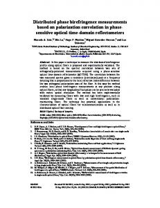
2. POLARIZATION SPLITTER A scanning-electron micrograph of the fabricated polarization splitter is shown in Fig. 1. This device is based on a simple directional coupler with silicon photonic wire waveguides. The coupling length for the TM mode, whose electric field is orthogonal to the substrate, is much shorter than for the TE mode, whose electric field is parallel to the substrate. Thus, the TM light can traverse the coupler, whereas the TE light propagates along the initial waveguide. In our design for 1550-nm infrared, a directional coupler consisting of 200-nm-high and 400-nm-wide cores with a 480-nm gap can separate two orthogonal polarizations through only 10-μm-long propagation. For a practical design, we have to pay attention to the bending radius around the coupler. For the suppression of additional coupling at the bending sections and for high-density integration, the ends of the coupler are tightly bent with a 3-μm radius. In the 200×400-nm rectangular core, TE mode light can propagate through the tight bend, but TM light can not. Therefore, we designed one waveguide to bend sharply for TE output and the other to be straight along the coupler for TM. The splitters were fabricated on silicon-on-insulator substrate with a 3-μm-thick buried oxide layer. For efficient coupling between the waveguides and external fiber, spot-size converters (SSCs) consisting of a silicon inverse taper and silica-based waveguide are attached to the ends of the waveguides [4]. The waveguide core and the silicon taper for SSC are fabricated by electron beam lithography and electron cyclotron resonance (ECR) plasma etching. The propagation losses measured by the cutback method are 2.2 dB/cm for the TE mode and 1.7 dB/cm for the TM mode. We measured the transmission of the splitter while rotating the incident polarization. The polarization was Bar(TE) controlled by by rotating a half-wave plate installed in front of the single-mode fiber for input. The experiment was 10 m IN performed at a fixed wavelength of 1552.52 nm. The measured transmission as a function of the wave-plate rotation angle are shown in Fig. 2(a). In the cross port, TM mode light is dominant and TE mode is suppressed; in the bar port, vice versa. The maximum polarization extinction ratios (PER) are 26 and 14 dB for bar and cross ports, Fig. 1. SEM image of the fabricated polarization splitter. respectively. Cascading two splitters is effective in
r Bar?! TE
-c C-)
E Co
C
TE
TM
TE
5 0
-20
Bar pot
-5
-10
Cross
Co
N
TM
-15 -20
(a)
Experiment (waveplate): TM -
.