© 2003 OSA/IPR 2003 IMC3.pdf
Polarization splitting and rotating through adiabatic transitions M. R. Watts, G. Gorni, M. Cherchi, H. A. Haus Research Laboratory of Electronics, Department of Electrical Engineering and Computer Science, Massachusetts Institute of Technology, MIT 36-355, 50 Vassar St., Cambridge, MA 02139 Tel (617)-253-5481,Fax (617)-253-9611,
[email protected]
Abstract: A polarization splitter and rotator that is compatible with optical integration is presented. In contrast to prior efforts to achieve this functionality, the adiabatic nature of this approach allows for nearly ideal performance over the 1.5-1.6µm regime. c 2003 Optical Society of America ° OCIS codes: (130.3120) Integrated optics devices; (130.2790) Guided Waves
High index contrast waveguides allow for small bend radii and thus enable dense integration of optical devices [3]. In high index-contrast systems it is difficult, if not impossible, to maintain degeneracy of the quasi-TE and quasi-TM modes across each and every structure on the chip thus causing polarization dependent performance. One approach to eliminate polarization sensitivity is to split the random polarization state emanating from the fiber into two orthogonal polarization states, rotate one of the states, and then perform identical operations on each in parallel [6]. In this way, the design and fabrication need only be optimized for a single polarization. For dense integration and elimination of the group delay between the paths, it is desireable to achieve both the splitting and rotation of polarization states in an integrated manner. In this configuration, the polarization splitting and rotating is done at the chip input, and thus must perform effectively across all optical channels propagating on the fiber. Any such approach must therefore possess low loss across a very broad optical spectrum. We consider rotation of the polarization. Many approaches to polarization rotation have been proposed [2, 4, 5, 6]. In each, the orthogonally polarized quasi-TE and quasi-TM modes of the guide are in one way or another coupled in order to invoke rotation. Coupling between orthogonally polarized modes is inherently difficult since the coupling must be achieved through minor field components. Thus, such structures are often complicated and difficult to fabricate. Moreover, coupled modes must be phase-matched, have precisely tuned coupling coefficients, and suffer from an inherent wavelength sensitivity. We propose a structure that seeks to transition the modes without invoking coupling. The approach is based on an adiabatic transition from a vertically aligned rectangular waveguide to a horizontally aligned rectangular waveguide. Although a pure rotation would be ideal, standard fabrication techniques dictate a layered structure. We consider a three layered approach with the core divided equally amongst the three-layers (Fig. 1a). The transition is made in a linear fashion with cross-sectional area removed from the top and bottom layers and added to the middle layer. By starting with a large aspect ratio rectangular waveguide we ensure the quasi-TE and quasi-TM modes propagate with greatly differing velocities and therefore dephase before they have a chance to exchange substantial power. Thus, despite the coupling introduced by the transition, the phase mismatch between the quasi-TE and quasi-TM modes mitigates coupling between them enabling rotation without mode mixing. The three-layered approach adopted for rotating the polarization allows for a natural approach to adiabatically split the polarization states within the same three layers. To split the polarizations, we begin with a horizontally oriented rectangular waveguide centrally intersected by an identical vertically oriented guide therein forming a cross structure (Fig. 1b). The quasi-TE and quasi-TM modes of the structure are degenerate. Despite this degeneracy upon slowly separating the guides there is no mechanism for the two modes to couple since the modes remain orthogonal throughout the length of the structure. These primary modes, however, may couple to secondary modes which appear as the two structures become distinct and lack the appropriate field symmetry to prevent coupling with their like polarized counterparts. However, the mode sets are not phase-matched and thus little power transfer occurs between the modes when the transition is made to be sufficiently adiabatic. Verification of the performance of these devices is achieved through the use of the three-dimensional mode
© 2003 OSA/IPR 2003 IMC3.pdf
Watts et.al., Polarization splitting and rotating...
IPR ’03/2003 Page
2
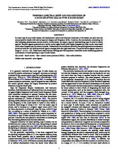
scattering formulation of [1]. The structures are those of Fig. 1a and Fig. 1b with a = 0.25µm, b = 0.75µm, a core index of 2.2 a cladding index of 1.445 with device lengths of 400µm and 150µm for the rotator and splitter, respectively. Scans of the transmission as a function of wavelength are presented in Fig. 2a and Fig. 2b. In each case greater than 99% of the power is transferred successfully across the entire 1.5-1.6µm band with greater than 25dB of suppression of the unwanted polarization states. Variations of these basic device designs will be presented along with an integrated mechanism for coupling to a standard SMF fiber.
References 1. Fimmwave by photon design. 2. J. Z. Huang, R. Scarmozzino, G. Nagy, M. J. Steel, and R. M. Osgood. Realization of a compact and single-mode optical passive polariztion converter. IEEE Photonics Technology Letters, 12:317–319, Mar 2000. 3. B. E. Little, S. T. Chu, P. Pan, and Y. Kokubun. Microring resonator arrays for vlsi photonics. IEEE Photonics Technology Letters, 12:323–325, Mar 2000. 4. W. W. Lui, T. Hirono, K. Yokoyama, and W. P. Huang. Polarization rotation in semiconductor bending waveguides. J. Lightwave Technol., 16:929–936, May 1998. 5. V. P. Tzolov and M. Fontaine. A passive polarization converter free of longitudinally periodic structure. Optics Communications, 127:7–13, Jun 1996. 6. M. R. Watts. Wavelength switching and routing through evanescently induced absorption. Master’s thesis, jun 2001.
© 2003 OSA/IPR 2003 IMC3.pdf
Watts et.al., Polarization splitting and rotating...
IPR ’03/2003 Page
E
(c)
E
E
a b
E
E
a
b E
E
E
b
a (a)
(b)
1.0
Modal Power (Normalized to Input)
Modal Power (Normalized to Input)
Figure 1. (a) Polarization rotator, (b) polarization splitter, and (c) integrated polarization splitter and rotator.
0.8 0.6 0.4 0.2 0.0
1.0 TE toTE
0.8
TM to TM
0.6 0.4 0.2 0.0
1.50
1.52
1.54 1.56 1.58 Wavelength (mm) (a)
1.60
1.50
1.52
1.54 1.56 1.58 Wavelength (mm) (b)
Figure 2. Transmission for (a) a 400µm long polarization rotator and (b) a 150µm long polarization splitter with a 1 µm separation of the core walls at the output. In each case a = 0.25µm, b = 0.75µm, and the core and cladding indices are 2.2 and 1.445.
1.60
3