Polarized backlight with constrained angular divergence for enhancement of light extraction efficiency from wire grid polarizer Po-Hung Yao, Chi-Jui Chung, Chien-Li Wu, and Cheng-Huan Chen* Department of Power Mechanical Engineering, National TsingHua University, HsinChu, 30013 Taiwan *
[email protected]
Abstract: Efficiency of liquid crystal displays highly depends on the amount of polarized light emerging from the backlight module. In this paper, a backlight architecture using a nanoimprint wire grid polarizer for polarization recycling is proposed and studied, in which the extraction efficiency of polarized light is the major concern. The backlight module is composed of the stack of a wire grid polarizer, a lenticular array and a light guide plate. The light guide plate features interleaving v-groove and trapezoidal ridge coated with aluminum on the top surface, and scattering dot array on the bottom. The angular divergence of emerging light from the light guide plate can be well constrained so as to exploit the angular range with the best transmission of polarized light for the wire grid polarizer. The prototype of a 2.5-inch module has demonstrated an angular divergence of 48°. The overall extraction efficiency of polarized light enhanced by 21% and uniformity of 76% have been achieved. ©2012 Optical Society of America OCIS codes: (110.2945) Illumination design; (120.2040) Displays; (220.4000) Microstructure fabrication.
References and links 1.
G.-J. Park, Y.-G. Kim, J.-H. Yi, J.-H. Kwon, J.-H. Park, S.-H. Kim, B.-K. Kim, J.-K. Shin, and H.-S. Soh, “Enhancement of the optical performance by optimization of optical sheets in direct-illumination LCD backlight,” J. Opt. Soc. Korea 13(1), 152–157 (2009). 2. Z. B. Ge and S. T. Wu, “Nanowire grid polarizer for energy efficient and wide-view liquid crystal displays,” Appl. Phys. Lett. 93(12), 121104 (2008). 3. T. Sergan, M. Lavrentovich, J. Kelly, E. Gardner, and D. Hansen, “Measurement and modeling of optical performance of wire grids and liquid-crystal displays utilizing grid polarizers,” J. Opt. Soc. Am. A 19(9), 1872– 1885 (2002). 4. J. J. Wang, L. Chen, X. M. Liu, P. Sciortino, F. Liu, F. Walters, and X. G. Deng, “30-nm-wide aluminum nanowire grid for ultrahigh contrast and transmittance polarizers made by UV-nanoimprint lithography,” Appl. Phys. Lett. 89(14), 141105 (2006). 5. P. C. Chen and H. L. Kuo, “Color shift improvement in a broadband cholesteric liquid crystal polarizer through computational simulations,” Proc. SPIE 7050, 705015, 705015-8 (2008). 6. L. Li, J. F. Li, B. S. Fan, Y. Q. Jiang, and S. M. Faris, “Reflective cholesteric liquid crystal polarizers and their applications,” Proc. SPIE 3560, 33–40 (1998). 7. Y. Iwamoto and Y. Iimura, “Transmitted light enhancement of electric-field-controlled multidomain vertically aligned liquid crystal displays using circular polarizers and a cholesteric liquid crystal film,” Jpn. J. Appl. Phys. 42, L51–L53 (2003). 8. X. J. Yu and H. S. Kwok, “Optical wire-grid polarizers at oblique angles of incidence,” J. Appl. Phys. 93(8), 4407–4412 (2003). 9. M. Xu, H. P. Urbach, D. de Boer, and H. Cornelissen, “Wire-grid diffraction gratings used as polarizing beam splitter for visible light and applied in liquid crystal on silicon,” Opt. Express 13(7), 2303–2320 (2005). 10. S. H. Baik, S. K. Hwang, Y. G. Kim, G. Park, J. H. Kwon, W.-T. Moon, S.-H. Kim, B.-K. Kim, and S.-H. Kang, “Simulation and fabrication of the cone sheet for LCD backlight application,” J. Opt. Soc. Korea 13(4), 478–483 (2009). 11. C. F. Lin, Y. B. Fang, and P. H. Yang, “Optimized micro-prism diffusion film for slim-type bottom-lit backlight units,” J. Disp. Technol. 7(1), 3–9 (2011).
#157887 - $15.00 USD (C) 2012 OSA
Received 11 Nov 2011; revised 20 Jan 2012; accepted 21 Jan 2012; published 13 Feb 2012 27 February 2012 / Vol. 20, No. 5 / OPTICS EXPRESS 4819
12. J. W. Lee, S. C. Meissner, and R. J. Sudol, “Optical film to enhance cosmetic appearance and brightness in liquid crystal displays,” Opt. Express 15(14), 8609–8618 (2007). 13. J. H. Lee, H. S. Lee, B. K. Lee, W. S. Choi, H. Y. Choi, and J. B. Yoon, “Simple liquid crystal display backlight unit comprising only a single-sheet micropatterned polydimethylsiloxane (PDMS) light-guide plate,” Opt. Lett. 32(18), 2665–2667 (2007). 14. S. Aoyama, A. Funamoto, and K. Imanaka, “Hybrid normal-reverse prism coupler for light-emitting diode backlight systems,” Appl. Opt. 45(28), 7273–7278 (2006). 15. K. Käläntär, “A directional backlight with narrow angular luminance distribution for widening viewing angle of a LCD with a front-surface-light-scattering film,” SID 11 Digest. 42(1), 890–893 (2011). 16. M. Born and E. Wolf, Principles of Optics, 4th ed. (Pergamon, 1970). 17. V. C. Ballenegger and T. A. Weber, “The Ewald–Oseen extinction theorem and extinction lengths,” Am. J. Phys. 67(7), 599–605 (1999). 18. K. Takano, H. Yokoyama, A. Ichii, I. Morimoto, and M. Hangyo, “Wire-grid polarizer sheet in the terahertz region fabricated by nanoimprint technology,” Opt. Lett. 36(14), 2665–2667 (2011).
1. Introduction Efficiency has been a critical issue for the development of liquid crystal display (LCD). The absorption at the down polarizer is one of the major factors leading to poor transmission of liquid crystal panels. Therefore, several research works have been proposed for increasing the utilization efficiency of polarized light emitting from backlight modules, and the majority are polarization recycling technology using different kind of reflective polarizers, such as multilayer birefringence film [1], metal wire grid polarizer (WGP) [2–4] and cholesteric liquid crystal film [5–7] etc. Among them, metal WGP possesses design parameters from its geometrical feature (as shown in Fig. 1(a)) and therefore becomes to attract more attention with the progress of nanostructure fabrication technology. Transmittance of linearly polarized light of a WGP depends not only on its geometrical feature but also on the light incident angle [8, 9]. Manipulation of light incident angle on WGP will then be helpful for the improvement of extraction efficiency of polarized light from the backlight module using WGP as the reflective polarizer for polarization recycling. But normally efficiency is not the only concern, one other major request is the enhancement of on-axis luminance for the best utilization of efficiency. Nevertheless, the corresponding solution normally benefits to both requests because a WGP in most cases shows best transmittance of polarized light at normal incidence. Consequently, a backlight module providing planar illumination with constrained angular divergence becomes a total solution for increasing and best utilization of efficiency. There have been several backlight architectures developed for the enhancement of on-axis luminance. The most widely used for current LCDs is the stack of multiple optical films, including diffuser, microlens film and prism film, on light guide plate. Multi-function optical films which integrate several functionalities into single component are also being developed [10–12]. Further integration can be made onto light guide plate to achieve more compact backlight structure [13–15]. Those backlight architecture can be helpful for the transmittance of polarized light from WGP, but with limited improvement because those design do not take the performance of WGP into consideration. In this paper, a polarized backlight module using a nanoimprint WGP as the reflective polarizer for polarization recycling has been used as the base architecture for improving the efficiency of LCD. The focus is on extracting as most linearly polarized light from the backlight module while maintaining the required uniformity. The angle-dependent transmittance of polarized light from a WGP has been investigated first and an architecture of a divergence-controlled backlight module (DC-BLM) is proposed to provide constrained angular divergence and exploit the best angular range of WGP. DC-BLM is composed of the stack of a lenticular array and a light guide plate, as shown in Fig. 1(b). The light guide plate features interleaving v-groove and trapezoidal ridge coated with aluminum on the top surface and scattering dot array on the bottom. The angular divergence and extraction efficiency of polarized light from WGP have also been evaluated on a 2.5-inch prototype.
#157887 - $15.00 USD (C) 2012 OSA
Received 11 Nov 2011; revised 20 Jan 2012; accepted 21 Jan 2012; published 13 Feb 2012 27 February 2012 / Vol. 20, No. 5 / OPTICS EXPRESS 4820
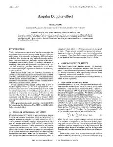
Fig. 1. (a) Wire grid polarizer and its birefringence property. (b) Schematic diagram of the polarized backlight module with WGP polarizer.
2. Angle-dependent transmittance of wire grid polarizer The total flux of polarized light Φop available for the liquid crystal panel shown in Fig. 1(b) depends on efficiency of optical components Eoc, polarization recycling efficiency Epr and linear polarization transmittance of the down polarizer Tpol. The relationship can be expressed as Eq. (1)
Φ op = Φ 0 × Eoc × E pr × Tpol
(1)
where Φ0 is the input flux and Epr=ΣEi, Ei refers to the extraction efficiency of polarized light of the ith recycling process. In this case, Φ0 depends on power of LED and Epr is related to the transmittance of WGP. Tpol is normally up to 80% for display-grade absorptive polarizers. With current technology, this absorptive down polarizer is indispensable for achieving extinction ratio up to 10000 for high contrast performance of LCD. Therefore, Eoc and Epr become the major effort to be made for improving efficiency. Wire grid polarizers feature periodic metal grating with pitch smaller than half of the wavelength, as shown in Fig. 1(a). The polarization perpendicular and parallel to the wire of the WGP are denoted by Pλ and Sλ respectively. According to the Ewald-Osceen extinction theorem [16, 17], most Pλ can transmit through the WGP while Sλ being reflected. The reflected Sλ polarization will be scattered and depolarized by the microstructure or ink print on the bottom of the light guide plate, so that the part of Pλ will be extracted from the backlight module next time hitting on the WGP. The process is referred as polarization recycling. The light propagating along the light guide plate will hit on the WGP many times. Therefore, in order to extract as most polarized light from the backlight module, transmittance of Pλ polarization (Tp) and reflectance of Sλ polarization (Rs) are major criteria to be considered and WGP with P = 140nm, wp = 92nm, and D = 210nm was obtained by using simulation program based on rigorous coupled-wave analysis (RCWA). The result indicates Tp≧75% and Rs≧80% over visible spectrum 400-700nm at normal incidence. The wire grid was made on a glass substrate with nano imprinting [18] and double-side oblique evaporation deposition processes. The cross-sectional profile of the wire grid taken by SEM is shown in Fig. 2(a) and the transmission in two orthogonal directions was examined in front of a LCD monitor as shown in Fig. 2(b).
#157887 - $15.00 USD (C) 2012 OSA
Received 11 Nov 2011; revised 20 Jan 2012; accepted 21 Jan 2012; published 13 Feb 2012 27 February 2012 / Vol. 20, No. 5 / OPTICS EXPRESS 4821
Fig. 2. (a) Cross-section profile of the nanoimprinted WGP from SEM. (b) Transmission property of the 5cmx5cm WGP on 4-inch glass substrate in two orthogonal directions examined in front of a LCD monitor. Double arrow denotes transmission axis for both LCD and WGP.
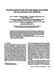
The spectral transmittance of WGP over visible spectrum at some oblique incident angles was simulated with RCWA and measured with spectrometer. The incident angle is changed from 0° to 40° with an increment of 10° and the results are shown in Fig. 3. The gap between simulation and measurement is mainly due to the deviation of nanostructure from an ideal flat top profile. Nevertheless, the percentage of transmittance drop with the increase of incident angle coincides with each other. Both measured and simulated data indicate that the transmission clearly depends on incident angle and it is reduced with the increase of incident angle by a percentage up to 10% with the incident angle increased from 0° to 30°. As a consequence, the narrower the angular divergence of incident light onto WGP, the higher the extraction efficiency of polarized light can be obtained from WGP. This leads to the motivation of facilitating a backlight module giving low divergence illumination for improving Epr while the module should have as less component as possible to avoid too much drop of Eoc upon the improvement of diverging angle, as indicated in Eq. (1).
Fig. 3. Spectral transmittance of WGP at some specific incident angles (solid line: measured data; dash line: simulation data).
3. Design and simulation of the backlight module In conventional LED edge-lit type backlight modules, light emitted from LEDs are scattered and distributed by dot pattern formed on the bottom surface of LGPs for a uniform planar illumination. Normally the emerging light from the top surface needs to be constrained within #157887 - $15.00 USD (C) 2012 OSA
Received 11 Nov 2011; revised 20 Jan 2012; accepted 21 Jan 2012; published 13 Feb 2012 27 February 2012 / Vol. 20, No. 5 / OPTICS EXPRESS 4822
a specific diverging angle for enhancing on-axis luminance. Therefore, various anglecontrolled films were developed [12–14] and stacked with diffuser films to achieve the required on-axis luminance while maintaining uniformity over the whole backlight surface. In order to improve the extraction efficiency when using WGP as the reflective polarizer for polarization recycling, there is a request of reducing the angular divergence from backlight even further to match the angular region with best spectral transmittance of WGP. An aperture-limited light guide plate (AL-LGP) is proposed, as shown in Fig. 4(a). There are onedimensional periodic trapezoid stripes on its top surface, where the plateau of each trapezoid stripe is coated with a 200nm thick aluminum layer as a reflective surface. The bottom surface is embossed with scattering dot pattern.
Fig. 4. (a) Schematic diagram of AL-LGP. (b) Illustration of possible ray path in AL-LGP.
Figure 4(b) shows some possible ray path for the light scattered from the bottom dot pattern. Ray Ii and IIIi are reflected and refracted back into the LGP by the Al layer and the adjacent trapezoid structure respectively. Those oblique rays hitting the side facets of the vgrooves at angles larger than critical angle of total internal reflection are reflected back to the bottom surface, as indicated with IVr in Fig. 4(b). Other rays shown as IIi impinging on the side facets are refracted and deflected toward the normal of top surface (z axis), i.e. emerging from the top surface with a reduced oblique angle from the surface normal. The overall diverging angle of emerging light is dependent of refractive index of the LGP material and the slanted angle β of the side facet of trapezoid structure. For a specified material of PMMA, the major design parameter becomes angle β. With the criteria of highest on-axis intensity while suppressing side-lobe as possible for the best transmittance of Pλ polarization for WGP, optimized value of β = 45° was obtained, which in turn makes the angle of V-groove α = 90°. In addition to the issue of diverging angle, the ratio of Al-coated area has significant influence on the efficiency and uniformity. Simulation shows efficiency drop and bar pattern when the ratio get too high. On the contrary, the emerging rays with small oblique angle are likely to be diverted away from the surface normal if the ratio gets too small, which in turn increases the diverging angle. Optimized ratio has been found between 30 and 40% so that the efficiency can be maintained above 70% and the uniformity above 65% without bar pattern mura. The optimized pitch and tip width of the trapezoid array becomes PT = 60 µm and w = 20 µm. Figure 5 shows the normally angular profile of the emerging light from the proposed AL-LGP with the Lambertian profile as the reference for comparison. The half angle is 84° compared to the 120° of Lambertian profile.
#157887 - $15.00 USD (C) 2012 OSA
Received 11 Nov 2011; revised 20 Jan 2012; accepted 21 Jan 2012; published 13 Feb 2012 27 February 2012 / Vol. 20, No. 5 / OPTICS EXPRESS 4823
Fig. 5. Angular profile of emerging light from AL-LGP compared with Lambertian profile.
With the exit of emerging ray being localized at the area of V-groove, a dedicated lenticular array, as shown in Fig. 6(a), is stacked onto the LGP with the lenslet facing downward and aligned with the V-groove for further reducing the diverging angle, as shown in Fig. 6(b), where PL is pitch of the lens; r is curvature radius of the lenslet; Ds and DL refer to thickness of PET substrate and sag of the lenticular lens respectively.
Fig. 6. (a) Lenticular array with feature parameters. (b) Configuration of AL-LGP covered with lenticular array.
In order to concentrate emerging rays within small diverging angle (i.e. narrower FWHM) corresponding to the efficient angular conditions of the WGP, parameters of the lenticular array were adjusted with the field distribution of AL-LGP by ray tracing principles. The ray path with associated denotation for the lenslet is shown in Fig. 7. Optical matrices have been employed as the paraxial ray tracing tool for determining the radius of curvature r of the lenslet.
Fig. 7. Geometry of optical ray tracing for the lenticular lenslet and the optical parameters for determining the optical matrices.
#157887 - $15.00 USD (C) 2012 OSA
Received 11 Nov 2011; revised 20 Jan 2012; accepted 21 Jan 2012; published 13 Feb 2012 27 February 2012 / Vol. 20, No. 5 / OPTICS EXPRESS 4824
1 φi As shown in Fig. 7, Ri = , i = 1-3 is the refractive matrix of each refractive 0 1 interface and ϕi = Ci (ni − 1) is the refractive power of each refractive interface and Ci is the
0 1 t curvature of each interface and n is refractive index; T j = j , j = 1,2 is the translation 1 − n j matrix between two interfaces and tj is the corresponding thickness and nj is the corresponding refractive index. The radius of curvature r can be derived from Eq. (2) after the focal length f is determined with the thickness parameters of lenticular array and WGP.
r = ( ƒ + Γ )( n − 1)
(2)
Ds + DL , nUV = nPET = n and f refers to effective focal length. n The parameters of the lenslet used in this case are listed in Table 1.
where Γ =
Table 1. Parameters of Lenticular Lenslet Index Value
DL 9µm
DS 50µm
nUV 1.59
nPET 1.59
Two criteria are considered to determine r of the lenticular lens, one is on-axis luminance gain for brightness performance of LCD panels and the other is FWHM for preserving the decay of angular transmission from WGP as lowest. Thus, combining the emission field of the optimized AL-LGP, radius of curvature r is optimized to be 55 µm with f = 100µm while the ray tracing simulation indicates that the FWHM diverging angle of the emerging light from DC-BLM has been reduced to 48° with an on-axis gain of 2.2x, as shown in Fig. 8. The corresponding performance of conventional backlight modules has also been simulated for comparison. The normalized angular profile of three other film combination, including diffuser only, diffuser plus one prism sheet and diffuser plus two prism sheets, are shown together in Fig. 8. It clearly shows that the proposed DC-BLM exhibits the narrowest angular divergence and the highest on-axis enhancement with the lowest side-lobe. Those performance indices for four cases are listed in Table 2. In addition, the tolerance for alignment between lenticular array and LGP has also been investigated and it indicates a drop of on-axis luminous intensity by 4% with a misalignment by one half pitch of lenticular lens.
#157887 - $15.00 USD (C) 2012 OSA
Received 11 Nov 2011; revised 20 Jan 2012; accepted 21 Jan 2012; published 13 Feb 2012 27 February 2012 / Vol. 20, No. 5 / OPTICS EXPRESS 4825
Fig. 8. Comparison of normalized intensity distribution of different backlight structures from simulation. Table 2. Comparison of Different Backlight Architectures Basing on the Same LED Input; Df: Diffuser Sheet, Pr: Prism Sheet. Performance Normalized Ion Gain FWHM (o) Module Thickness (mm)
Df 0.45 1 120°
Df+Pr 0.64 1.4 80°
Df+2xPr 0.92 2 66°
DC-BLM 1 2.2 48°
0.9
0.97
1.05
0.9
Figure 9 shows the simulated illuminance distribution over a 2.5” backlight module using the proposed DC-BLM configuration, and the uniformity is estimated to be 73%.
Fig. 9. Illuminance distribution of DC-BLM with stack of AL-LGP and the lenticular array by simulation.
#157887 - $15.00 USD (C) 2012 OSA
Received 11 Nov 2011; revised 20 Jan 2012; accepted 21 Jan 2012; published 13 Feb 2012 27 February 2012 / Vol. 20, No. 5 / OPTICS EXPRESS 4826
4. Performance evaluation of DC-BLM with WGP The AL-LGP and lenticular array have been fabricated with the process shown in Fig. 10(a) and 10(b) respectively. AL-LGP is made of PMMA and lenticular array is made of acrylic resin on a PET substrate by UV-curing process. The prototypes are shown in Fig. 11(a) and 11(b) respectively.
Fig. 10. (a) Diamond tooling process for AL-LGP. (b) Fabrication process for the lenticular sheet.
Fig. 11. (a) 2.5-inch PMMA AL-LGP. (b) 2.5-inch PET lenticular array film replicated by UV imprint process with a grooved master mold.
5-point on-axis luminance of the 2.5-inch DC-BLM was taken by a luminance meter and the result is shown in Fig. 12(a). Additionally, the angular intensity distribution was also measured with the IS-VA system from Radiant Image and the result is shown in Fig. 12(b). In good agreement with the simulation result, the FWHM angular divergence of 48° is achieved and the on-axis brightness is enhanced by 120% with uniformity of 76%.
#157887 - $15.00 USD (C) 2012 OSA
Received 11 Nov 2011; revised 20 Jan 2012; accepted 21 Jan 2012; published 13 Feb 2012 27 February 2012 / Vol. 20, No. 5 / OPTICS EXPRESS 4827
Fig. 12. (a) 5 points on-axis luminance of the 2.5-inch DC-BLM. (b) Measured angular intensity of the proposed DC-BLM and a diffuser-stacked module.
Enhancement of extraction efficiency for polarized light from WGP has been evaluated by using an additional absorptive polarizer and an integrating sphere detector was used to measure the total output flux of the whole assembly, including DC-BLM, WGP and absorptive polarizer. The result is compared with that of the case where DC-BLM is replaced with a cross-prism-stacked backlight module (CPS-BLM) in where one diffuser and two cross-oriented prism sheets are stacked, as listed in Table 3. The DC-BLM has lower optical component efficiency Eoc, reasonably due to aperture limited configuration with Al coating. However, the overall extraction efficiency of polarized light gets higher due to higher polarization recycling efficiency, which attributes to the lower divergence angle of emerging light. As a result, the polarized output flux and the on-axis brightness are enhanced by 21% and 5% respectively with the case of CPS-BLM as reference. Table 3. Optical Performance of the DC-BLM and Cross-Prism-Stacked BLM (CPSBLM) 2.5-inch LED BLU Φ0 (lm) Eoc Epr Tpol Φop(lm) DC-BLM+WGP+Polarizer 7.1 66% 75% 80% 2.81 CPS-BLM+WGP+Polarizer 7.1 76% 54% 80% 2.33 Gp:flux gain of polarized light; Lon: on-axis luminance; GL: on-axis luminance gain.
Gp 1.21 1
Lon (nit) 451 428
GL 1.05 1
5. Conclusions For the backlight illumination of liquid crystal displays, only the part of linearly polarized light contributes to the effective total lumen and efficiency. Based on the scheme of polarization recycling with wire grid polarizer, the proposed backlight module provides illumination source with low angular divergence and highly suppressed side lobe component, which has been demonstrated as an effective approach for enhancing the overall extraction efficiency of polarized light. The general requirement of on-axis luminance enhancement is naturally fulfilled in the mean time, and the uniformity performance can also be met with proper design on the available parameters in the proposed architecture. This indicates that the proposed architecture can be a feasible total solution from all performance aspects of LCD backlight module with the emphasis on efficiency enhancement. Number of the components in the whole module is relatively few, which could be considered as an additional advantage for the potential of slim backlights.
#157887 - $15.00 USD (C) 2012 OSA
Received 11 Nov 2011; revised 20 Jan 2012; accepted 21 Jan 2012; published 13 Feb 2012 27 February 2012 / Vol. 20, No. 5 / OPTICS EXPRESS 4828
Acknowledgments Authors would like to thank T. H. Lin at ITRI for the support of diamond tooling process of fabrication for the prototypes and this research is sponsored by the MOEA project under grant number 100-EC-17-A-07-S1-137.
#157887 - $15.00 USD (C) 2012 OSA
Received 11 Nov 2011; revised 20 Jan 2012; accepted 21 Jan 2012; published 13 Feb 2012 27 February 2012 / Vol. 20, No. 5 / OPTICS EXPRESS 4829