831 POLING OF VDF/TrFE COPOLYMERS USING A STEP-WISE METHOD Dadi SETIADI I), T. David BINNIE I), Paul REGTEN
2,
and Michael WUBBENHORST 3,
1) Napier University, 219 Colinton Road, Edinburgh EH14 1DJ U. K. 2) University of Twente, P.O.Box 217,7504 AE Enschede, Netherlands 3) Delft University of Technollogy, P.O.Box $?54,2600 GA Delft, Netherlands
Abstract A new poling technique is presented, in which a series of five consecutive pulses of electric field, and with successively increasing strength is applied between the two electrodes of 65/35 VDF/TrFE copolymer based sensor. Between each pulse, the applied electric field is reduced to zero (short circuit). This stllows deformations and space charges to be relax, resulting in more homogeneous electric field distribution with less risk for an electric breakdown. It is conducted at room temperature and is compatible with semiconductor technology. This stepwise poling technique is characterised by a low breakdown rate and yields a high pyroelectric coefficient.
1. Introduction
Since the mid 1980's integrated pyroelectric sensors based on VDFRrFE copolymer have been intensively studied [11. Copolymer deposition and recrystallization are low temperature processes and are compatiblie with the semiconductor technology. To achieve more active pyroelectric device, the copolymer must be poled, preferably on-chip and at room temperature without damaging the readoul electronics. Polarisation methods For VDFlTrE copolymers are generally based on the application of a high electric field across, the thickness of the copolymer film The resulting pyroelectric coefficient of the copolymers depends on the degree of polarisation and thus on the applied field strength. Electrode polling (thermal poling) method uses the direct application of a potential difference across electrodes mounted on the two sides of the film at room temperature or elevated temperatures [2]. In corona poling, one deposits charge of opposite polarities on the film surfaces by exposing at least one surface to a corona discharge [3]. With electron-beam poling, the front surface of the polymer f h is irradiated, while the rear surface is connected to ground [4]. The polarisation profiles achieved with the corona poling and electron-beam poling are less uniform than with electrode (thermal) poling. Furthermore, these two methods are not proficient for on-chip poling of VDFnrFE copolymers deposited on an integrated silicon substrate due to the risk of damage to the readout electronics. The application of a high electric field involves the risk of electric and thermal breakdowns, particularly if the film thickness is not constant or if the film contains imperfections, voids or impurities. Breakdown then occurs at a lower field than the electric breakdown strength of the copolymer.
CH35808/96/0-7803-2695-4$04l.00 Copyright 1996 IEEE
832 A new poling method has been developed to realise on-chip poling. Advantages of the poling method are a low failure rate due to electric and thermal breakdowns and a sufficient high pyroelectric coefficient. This method is called a step-wise poling which will be presented in this paper. 2. Theory
By the application of an electric field to the copolymer with both surfaces are coated with aluminium electrodes, crystallite dipoles are oriented. Simultaneously, charges are injected into the copolymer through the electrodes. Both the orientation of dipoles and the injected charges, depend on the field strength. After the dipoles are aligned in the field direction, charge trapping at the crystallite surface is possible. If the field is switched off, the dipoles keep their orientation in the field of these trapped charges. The &pole orientation under field alone makes this orientation not remnant after removing the field. The dipoles are stabilised by the field of trapped charge [5]. All dipoles that are not fixed in the field of trapped charge distribute ' randomly because of their thermal energy. They do not contribute to the remnant polarisation. Vice versa, injected charges that are not trapped leave the film under short circuit condition. The trapped charges that are injected through the electrodes are essential for polarisation. The resulting remnant polarisation is more than an order of magnitude smaller when poled with blocking PETP film electrodes that hinder the charge injection into the copolymers [6].Nevertheless, this injected charge results in a highly inhomogeneous electric field distribution. Consequently, the equilibrium state of the copolymer is disturbed and the breakdown occurs, When a short circuit condition is introduced between pulses of high electric field (see Figure l), these charges leave the copolymer, resulting in more homogeneous electric field distribution. Moreover, because the trapped charges compensate for the polarisation of the crystallites, there is no residual electric field in the copolymer. If an electric field is applied into prepolarized copolymers, more dipoles are fixed into the direction of the field, and the remnant polarisation increases. If the electric field strength of this second stage is more stronger the first stage, a proficient growth of the remnant polarisation is yield and risk of electric breakdown is less than when the same electric field strength is applied into unpolarized copolymers. Since the charges are already present in polarised copolymer, the injected charges are hmited. A current induced by the injected charges is also limited. Therefore, the probability for a thermal breakdown is reduced.
~
i
3. Preuaration and Poling The VDFRrFE copolymer sample was formed using one gram powder of 65 mol% vinylidene fluoride and 35 mol% trifluoroethylene dissolved in hot methyl ethyl katone, resulting in a 10 wt% concentration. The solution is spun on an aluminated silicon substrate, resulting 1 pmthick film with 5 % uniformity. The sample is annealed as follows: first, the sample is kept for 24 hours at 25 OC. Then, the annealing temperature is increased to 100 OC. The sample is kept at this temperature for six hours, and an anneal for 10 minutes at 160 OC follows. Finally, the annealing temperature is slowly decreased to 25 OC in 4-5 hours. Finally, an aluminium top electrode is deposited.
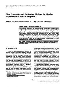
833 Step-wise poling is performed by a series of five consecutive pulses of several minutes, and with successively increasing amplitude. The maximum field strength is 100 VIpm, with a constant increase of 20 VIpni, as shown in Figure 1. The pulse width where the electric field is applied between two aluminium electrodes is the poling interval. Between two poling intervals (pause), the applied electric field is zero (short circuit). The poling is conducted at room temperature. The advantage of the step-wise poling is that the probability for both electrical and thermal breakdowns is reduced, compared with electrode poling. The chance for an electric breakdown is decreased because more homogeneous electric field distribution during the poling and the same polarisation is achieved at a lower field strength, compared to electrode poling. The probabilities of a thermal breakdown also decrease due to limited current through the film. A disadvantage of the step-wise poling is the longer polarisation time. With the stepwise poling, up to 50 minutes is needed to polarise the copolymer, instead of five to ten minutes as an electrode poling [7].
'E' 1
5
loo
E
xo poling time pause
Figure I Schematic of the step-wise poling technique. Tp is poling interval (electric field is applied between two electrodes) and ti is pause (short circuit).
4 Exueriment Results The pyroelectric Coefficient of the 65/35 VDF/TrF% copolymer has been measured using a combined quasistatic and dynamic technique (MTSD, Modulated Thermally Stimulated Discharge). Table 1 shows the pyroelectric coefficient of the 65/35 VDFlTrFE copolymer using the step-wise poling as a function of the poling interval and the pause. These values are measured at 25 'C. The pyroelectric coefficient increases with increasing poling interval (from 4 to 8 minutes). Yamazaki et. al have reported that the pyroelectric coefficient showed no dependence on the poling time from 5 up to 120 minutes [7]. Therefore, the time is needed in
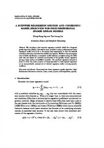
a34 which a l l dipoles are aligned into the field direction reaches its maximum is 5 minutes. It explains an increase of the pyroelectric coefficient from 2.0 to 3.1 nC/cmZK.The pyroelectric coefficient increases with increasing pause (from 2 to 4 minutes), excepting from 1 to 2 minutes. The relationship between the pause and the obtained pyroelectric coefficient is not yet understood. Figure 2 shows the pyroelectric coefficient of 65/35 VDF/TrFT copolymer as a function of the temperature. Here, the poling interval is eight minutes and the pause is one minute. The pyroelectric coefficient of the copolymer samples using the step-wise poling is higher than using electrode poling for the same field strength as reported in the previous paper
PI. Table 1
Pyroelectric coefficient of the 65/35 VDFRrFE copolymer
poling interval [minl
pause [min]
4 8
1 1 2
8
pyroelectric coefficient [nC/cm*K] 230 3,1 3,O
Pyroelectric
[email protected]'ent of the 65/35 VDFflrFE copolymer
1.OOE+OO
20
25
30
35
40
45
SO
55
60
temperature T [ C] Figure 2 Pyroelectric coeficient of the 65/35 VDFflrFE copolymer [8]. Here, the poling interval is eight minutes and the pause is one minute.
Measurements on many samples, poled either with electrode poling or step-wise poling gave a strong indication that indeed, the step-wise poling significantly reduces the probability
a35 of breakdown. The improving effect of a slowly increasing electric held was already reported by Kohler [lo] and Bauer [ I l l . Kohler discussed the reduced breakdown rate in terms of piezoelectricity generated mechanical deformation during poling. 4. Discussion By introducing periods of zero field between pulses of high electric field, the space charges that are not trapped leave the copolymer, resulting in more homogeneous electric field distribution with less risk for an electric breakdown. The development of the remnant polarisation is faster and of sufficient strength when the electric field is applied to the prepolarized copolymer. The step-wise poling is appropriate for on-chip poling of the VDF/TrFE copolymer. It is conducted at room temperature and is compatible with semiconductor technology. The technique is characterised by a low breakdown rate and yields a sufficient high pyroelectric coefficient.
REFERENCES D. Setiadi, “Integrated VDF/TrFE copolymer-on-silicon pyroelectric sensors” Ph.D.’s thesis, University of Twente, 1995. H. Yamazaki, J. Ohwa.ki, T.Yamada, and T. Kitayama, “temperature dependence of the pyroelectric response of vinylidene fluoride-trifluoroethylenecopolymer and the effect of its poling conditionis” Appl. Phys. Lett., Vo1.39 (1981), pp.772-773. J.A. Giacometti, J. Sinezio, C. Campos, N. Alves, and M.M. Costa, “The electrical behaviour of PVDF anid P)VDF/TrFE) during corona poling “ IEEE 1990 Annual Report Conf. Elec. Insul. and Dielec. Phen, pp. 77-82. B. Gross, R. Gerhard-IMulthaupt, A. Berraissoul, and G. M. Sessler, “Electron-beam poling of piezoelectric polymer electrets” J. Appl. Phys., Vol. 62 (1987), pp. 14291431. M. Womes, E. Bihler, and W. Eisenmenger, “Dynamics of polarisation growth and reversal in PVDF films”, IEEE trans. on. Elec. Insl. Vol. 28 (1993), pp. 344-348. E. Bihler, G. Neumanrr, G. Eberle, W. Eisenmenger, “Influence of charge injection on formation of remnant polarisation in P(VDF/TrFE) copolymer”, IEEE Annual Report Conf. Elec. Insl. and Dielec. Phen. (1990), pp. 140-145. H. Wamazaki, J. Ohwaki, T. Yamada and T. Kitayama, “temperature dependence of the pyroelectric responise of vinylidene trifluoroethylene copolymer and the effect of its poling condition”, App. Phy. Lett. Vol. 39 (1981), pp. 772-773. D. Setiadi, M.Wubberthorst, and P.P.L. Regtien, The Step-wise poling of a thin VDlWrFE copolymer, 8-th European meeting on ferroelectricity, Nijmegen, The Netherlands, July 4-8, 1995, pp.pl4-08. D. Setiadi, P.P.L. Regtien and P.M. Sarro, “Application of VDF/TrFE copolymer for pyroelectric image sensors”, Sensors and Actuators A, Vol. 42 (1994), pp. 585-592. R. Kohler, “Poly(viny1lidenefluoride-trifluoroethylene)in pyroelektrischen strahlungssensoren”, PhD dissertation, Dresden, 1992. F. Bauer, Fr. Patent No. 8221025, 1982; US Patent No. 461 1260, 1984.