APPLIED PHYSICS LETTERS 96, 143506 共2010兲
Polyelectrolyte junction field effect transistor based on microfluidic chip Kwang Bok Kim,1 Ji-Hyung Han,2 Hee Chan Kim,3,a兲 and Taek Dong Chung2,a兲 1
Interdisciplinary Program, Bioengineering Major, Graduate School, Seoul National University, Seoul 110-744, Republic of Korea 2 Department of Chemistry, Seoul National University, Seoul 151-747, Republic of Korea 3 Department of Biomedical Engineering, College of Medicine and Institute of Medical and Biological Engineering, Medical Research Center, Seoul National University, Seoul 110-744, Republic of Korea
共Received 14 December 2009; accepted 23 March 2010; published online 9 April 2010兲 This study developed the first polyelectrolyte junction field effect transistor capable of operating in an aqueous microfluidic network on a chip. In this system, polydiallyldimethylammonium chloride and poly-2-acrylamido-2-methyl-1-propanesulfonic acid are used for the elaborate control of the ion flow by selective extraction of anions and cations from the microchannel. The rate of ion extraction can be regulated by simply adjusting the gate voltage, and it results in ion depletion in the vicinity of the polyelectrolyte plugs. The extent of ion depletion between the polyelectrolyte plugs is a sensitive function of the ion resistance of the microchannel; therefore, the current between the source and the drain can be controlled by regulating the gate voltage. © 2010 American Institute of Physics. 关doi:10.1063/1.3389492兴 Micrototal analysis systems for the pretreatment, separation, and detection of biological samples on microfluidic chips have received huge attention, and much advancements have been made over the last two decades.1 Numerous technologies have been incorporated in the on-chip total analysis systems for exploring new applications. One of the most successful combinations between technology and chip is electrokinetic strategy to handle the flow in microfluidic chips. The precise and quick electrokinetic control of the fluids in the microfluidic networks substituted for mechanical pumps in many chip applications, such as electrophoretic separations and automatic injections.2 Salt bridges added fuel to electric control and detection for advanced microfluidic chips, which are equipped with a variety of functions. The first example was to use a silicate layer for electrokinetic fluid control and the creation of field-free generation in the microfluidic network.3–5 From the simple applications at the early stage, the salt bridges on chips have evolved into complicated devices and now are emerging as novel promising components. A pair of gel plugs facing to each other produced a highly efficient impedometric cell counter,6 an active ionic mixer enabling quick treatment between human blood and reagents,7 and an electroporation chip operating at only 10–20 V of dc voltage.8 More importantly, the polyelectrolyte plugs offer even more interesting functions to the chip systems. Cationic and anionic polyelectrolyte plugs under an electric field allow anions and cations to carry corresponding charge, respectively. Therefore, an electric field can induce charge-selective ion current through the polyelectrolyte plugs, which may be used for the selective extraction of cations or anions from a microchannel, leading to ion depletion that occurs in the vicinity of the polymer phases. This behavior can be observed around polyelectrolyte plugs owing to overlap of the electric double layers near the polymer backbones, which are normally several nanometers thick from the charged surfaces. The principle underlying the preconcentraa兲
Authors to whom correspondence should be addressed. Electronic addresses:
[email protected] and
[email protected]. FAX: ⫹82-2-20721615 and ⫹82-2-745-7870.
0003-6951/2010/96共14兲/143506/3/$30.00
tors based on nanochannels is basically same.9–11 In contrast to nanochannels, polyelectrolyte gels provide threedimensional nanofluidic pathway for ions to flow through even wider cross-sectional area, resulting in a much more efficient ion extractor. Polyelectrolyte gels can be easily fabricated by photopolymerization using a mask, and their properties can be modified by simply choosing different monomer or cross-linker. On the other hand, new circuitry concept working in an aqueous microfluidic system has attracted keen attention recently. Cationic and anionic polyelectrolyte plugs, which are adjacent to each other at a narrow neck, act as a diode showing an impressive nonlinear rectification behavior. A couple of the fascinating “aqueous diode” was integrated to yield ionic logic circuits on a microfluidic chip, which was named “iontronics.”12 Compared to nanopore and nanofluidic diodes,13–15 this polyelectrolyte-based diode system on a chip is practical and readily available for microfluidic logic circuits because of its simple fabrication, extendibility, and versatility in terms of functional modification. In addition to nanofluid-based diodes, nanofluidic transistors were also introduced and their applications in protein transport and electrostatic control of ions and DNA were reported.16–18 The recent progress in this field strongly implies that the first transistor based on polyelectrolyte iontronics will be developed. In this paper, we report a polyelectrolyte junction field effect transistor 共pJFET兲 that is developed on a microfluidic chip. The proposed system is the first microfluidic transistor based on polyelectrolytes, which are charge-selective polymers of polydiallyldimethylammonium chloride 共pDADMAC兲 and poly-2-acrylamido-2-methyl-1-propanesulfonic acid 共pAMPSA兲. As shown in Fig. 1, the polyelectrolyte plugs were formed at two spots in the microchannel network. The positively charged 共pDADMAC兲 and negatively charged 共pAMPSA兲 polyelectrolytes allow the selective passage of anions and cations, respectively. The ion current of the mainchannel is sensitively affected by the extent of ion depletion that is caused by intensive ion extraction through the polyelectrolyte plugs under a gate voltage. The region where the
96, 143506-1
© 2010 American Institute of Physics
Downloaded 13 Apr 2010 to 147.47.217.184. Redistribution subject to AIP license or copyright; see http://apl.aip.org/apl/copyright.jsp
143506-2
Kim et al.
Appl. Phys. Lett. 96, 143506 共2010兲
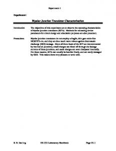
FIG. 1. 共Color online兲 Schematic of a pJFET microfluidic chip. A pair of oppositely facing polyelectrolytes, pDADMAC, and pAMPSA, is positioned on the microchannel wall. The cross section of each polyelectrolyte has a depth of 30 m and a width of 200 m. Cations and anions in the microchannel are extracted locally by applying the gate voltage through these charge-selective polyelectrolytes. The gate voltage is applied across two different polyelectrolytes and the source-drain current flowing between the inlet and outlet of the mainchannel is measured.
ion depletion occurred was identified by fluorescence imaging of positively and negatively charged dyes, rhodamine 6G and fluorescein, respectively. The characteristics of the proposed pJFET were demonstrated by ID versus VG curves, where ID is the current between the source and drain and VG is the gate voltage. A microfluidic chip for a pJFET, with 70 m wide and 30 m deep microchannels was fabricated using standard photolithography technique, as described in previous studies.12,19 The surface of a Corning 2947 slide glass was washed with piranha solution 共H2O2 : H2SO4 = 1 : 3兲 and coated with hexamethyldisilazane by a spin coater so that the photoresists 共PRs兲 were firmly adhered to the glass. The slide glass coated with PR AZ4620 was aligned under a patterned mask and exposed to UV light 共MDE-4000兲 with an intensity of 15 mW/ cm2 for 10 s. The PR was removed by using an AZ 400 K developer and etched for 45 min in 6:1 buffered oxide etching solution. Then, four holes were drilled into the glass chip for inserting a source, a drain, and two gate electrodes. Lastly, a flat cover glass with the same size was washed for 45 min with the piranha solution and used for thermal bonding. The polyelectrolyte plugs were fabricated by photopolymerization. The positively and negatively charged monomers were DADMAC and AMPSA, respectively. First, the microchannel was coated with 0.5% 3-共trimethoxysilyl兲 propylmethacrylate and filled with a 65% DADMAC solution that contained a photoinitiator 共2%兲 and a cross-linker 共2%兲. The microfluidic chip was aligned under a patterned mask film and exposed to UV light at 15 mW/ cm2 for 2 s. After polymerization, the residual DADMAC monomers were removed by rinsing with 1 M KCl. For fabricating a pAMPSA plug, the microchannel was filled with a 2 M AMPSA solution that contained a photoinitiator 共2%兲 and a cross-linker 共2%兲, and was exposed to UV light with the same intensity for 3 s. The microfluidic chip comprising pDADMAC and pAMPSA plugs was stored in a 10 mM KCl solution.
FIG. 2. 共Color online兲 Mechanism underlying the control of ionic flow and fluorescence images of the fluorescein and the rhodamine 6G for tracking the movement of the anions and cations by adjusting the gate voltage in the system. 共a兲 When the gate voltage is not applied, cations and anions are equally distributed in the microchannel. The fluorescein 共anionic dye兲 and the rhodamine 6G 共cationic dye兲 are diffused into the positively charged pDADMAC and negatively charged pAMPSA, respectively. 共b兲 When a gate voltage is applied, fluorescein and rhodamine 6G are rapidly extracted from the microchannel, and the ion concentration between the polyelectrolytes decreases. 共c兲 As the gate voltage is increased, an ion depletion region appears in the middle of the mainchannel and subsequently expands.
To observe the distribution of the fluorescent dyes in the microchannel, a fluorescence microscope, TE-2000 共Nikon兲, mercury lamp, and 12-bit ProgRes C3 CCD camera 共JENOPTIK兲 were used. Gate voltage generated by a dc power supplier 共Xantrex兲 was applied to platinum electrodes that were connected to gate reservoir of the microfluidic chip, while an electrochemical analyzer—CHI 750 共CH Instruments Inc.兲— was used for measuring the change in the current, ID flowing between the inlet and outlet of the mainchannel. As a gate voltage was applied to the polyelectrolytes, pDADMAC and pAMPSA, the ions between the polyelectrolytes were extracted from the mainchannel. To confirm this ionic flow, the behavior of anionic fluorescein and cationic rhodamine 6G dyes was monitored using a fluorescence microscope. Figure 2 shows the formation and subsequent expansion of an ion-depleted region. Under an external gate voltage, 10 M fluorescein molecules in 10 mM KCl solution quickly passed through the pDADMAC plug, and this rapid extraction of anions drove cations out of the region in order to maintain charge neutrality. Ion depletion was also observed near the pAMPSA plug in the 10 M rhodamine 6G in 10 mM KCl solution; this ion depletion can be attributed to the same principle mentioned above. Thus, the charge-selective extraction of anions and cations through the pDADMAC and pAMPSA plugs generated ion depletion in
Downloaded 13 Apr 2010 to 147.47.217.184. Redistribution subject to AIP license or copyright; see http://apl.aip.org/apl/copyright.jsp
143506-3
Appl. Phys. Lett. 96, 143506 共2010兲
Kim et al.
microfluidic networks. The pJFET has the great potential for evolving into more versatile utilities such as multifunctional ionic circuits by suggesting new opportunity to aqueous information processors.
FIG. 3. 共Color online兲 Output characteristics of a pJFET. The source-drain current, ID, is directly related to the ion depletion region formed by the gate voltage. When the gate voltage is increased from 0 to 6 V, ID decreased because of the large ion depletion region, which reduces the conductivity of the microchannel. Each point is tested five times.
This research was supported by the Nano/Bio Science & Technology Program 共Grant No. M10536090001-05N360900110兲 of the Ministry of Education, Science and Technology共MEST兲, by the MKE 共Ministry of Knowledge Economy兲, Korea, under the ITRC 共Information Technology Research Center兲 support program supervised by the NIPA 共National IT Industry Promotion Agency兲 关Grant No. NIPA-2009共C1090-0902-0002兲兴, by the grant from the Industrial Source Technology Development Program 共Grant No. 10033657兲 of the Ministry of Knowledge Economy 共MKE兲 of Korea, and by a grant from the Fundamental R&D Program for Core Technology of Materials funded by the Ministry of Knowledge Economy, Republic of Korea. T. Vilkner, D. Janasek, and A. Manz, Anal. Chem. 76, 3373 共2004兲. S. C. Jacobson, R. Hergenroder, L. B. Koutny, R. J. Warmack, and J. M. Ramsey, Anal. Chem. 66, 1107 共1994兲. 3 J. Khandurina, S. C. Jacobson, L. C. Waters, R. S. Foote, and J. M. Ramsey, Anal. Chem. 71, 1815 共1999兲. 4 S. Song, A. K. Singh, and B. J. Kirby, Anal. Chem. 76, 4589 共2004兲. 5 A. V. Hatch, A. E. Herr, D. J. Throckmorton, J. S. Brennan, and A. K. Singh, Anal. Chem. 78, 4976 共2006兲. 6 H. Chun, T. D. Chung, and H. C. Kim, Anal. Chem. 77, 2490 共2005兲. 7 H. Chun, H. C. Kim, and T. D. Chung, Lab Chip 8, 764 共2008兲. 8 S. K. Kim, J. H. Kim, K. P. Kim, and T. D. Chung, Anal. Chem. 79, 7761 共2007兲. 9 Y.-C. Wang, A. L. Stevens, and J. Han, Anal. Chem. 77, 4293 共2005兲. 10 S. M. Kim, M. A. Burns, and E. F. Hasselbrink, Anal. Chem. 78, 4779 共2006兲. 11 J. H. Lee, B. D. Cosgrove, D. A. Lauffenburger, and J. Han, J. Am. Chem. Soc. 131, 10340 共2009兲. 12 J.-H. Han, K. B. Kim, H. C. Kim, and T. D. Chung, Angew. Chem. Int., Ed. 48, 3830 共2009兲. 13 Z. S. Siwy, Adv. Funct. Mater. 16, 735 共2006兲. 14 I. Vlassiouk, T. R. Kozel, and Z. S. Siwy, J. Am. Chem. Soc. 131, 8211 共2009兲. 15 R. Karnik, R. Fan, M. Yue, D. Li, P. Yang, and A. Majumdar, Nano Lett. 5, 943 共2005兲. 16 H. Daiguji, P. Yang, and A. Majumdar, Nano Lett. 4, 137 共2004兲. 17 R. Fan, M. Yue, R. Karnik, A. Majumdar, and P. Yang, Phys. Rev. Lett. 95, 086607 共2005兲. 18 R. Karnik, K. Castelino, and A. Majumdar, Appl. Phys. Lett. 88, 123114 共2006兲. 19 K. B. Kim, H. Chun, H. C. Kim, and T. D. Chung, Electrophoresis 30, 1464 共2009兲. 1
the middle of the microchannel between the source and the drain. In conventional JFETs, the source-drain current, ID, is controlled by the gate voltage, VG, which causes the depletion region to adjust the channel conductivity between the source and the drain. When a gate voltage was applied to the proposed pJFET system, an ion depletion region was formed in the aqueous solution, rather than in the semiconductors of the JFETs. This ion depletion causes a drop in the conductivity of the microchannel. As shown in Fig. 3, ID is a sensitive function of VG. Therefore, the behavior of the proposed pJFET system is similar to that of a conventional JFET; however, these two systems differ with respect to the charge carriers, the working principles, and the medium through which the current flows. In this study, we have demonstrated a pJFET system that operates in an aqueous medium by reliably controlling the ionic flow through oppositely charged polyelectrolyte plugs. The applied VG causes ion depletion in the middle of the main microchannel, which regulates ID. This system does not require a complicated and sophisticated process such as nanofabrication. Despite the simple structure and short fabrication process, the polyelectrolyte plugs are remarkably more effective tools for ion extraction than nanochannels. Hence, an ion depletion region can be rapidly created in the
2
Downloaded 13 Apr 2010 to 147.47.217.184. Redistribution subject to AIP license or copyright; see http://apl.aip.org/apl/copyright.jsp