Polymeric Nanocomposites Enabled by Controlled Architecture Materials Terri A. Shefelbine*, Ryan E. Marx**, James M. Nelson*, John W. Longabach**, Myles L. Brostrom***, Mary I. Bucket*** **3M Corporate Research Process Lab ***3M Corporate Research Analytical Lab * 3M Dyneon LLC 6744 33rd St. N. Oakdale, MN 55128 Office: 651-737-5099
[email protected] ABSTRACT Clay nanocomposites have been shown to improve barrier properties, increase modulus, increase heat distortion temperature, and improve flame retardancy. To fully utilize these benefits, the clay platelets must be exfoliated and dispersed within the polymer. It is well known that clay will readily exfoliate in some polymeric resins, e.g. nylon. For hydrophobic resins, such as polyolefins, the exfoliation process is much more difficult. 3M is currently developing a portfolio of Controlled Architecture Materials (CAMs) as specialty additives for a variety of applications, including clay nanocomposites. In this paper we demonstrate the ability of CAMs to exfoliate both organically modified and unmodified natural clays in polystyrene (PS) and polypropylene (PP) resins. Complementary characterization techniques of Transmission Electron Microscopy (TEM), x-ray diffraction (XRD), and rheology are used to identify exfoliation. In addition we demonstrate the efficiency of CAMs to exfoliate clay at low additive levels. Keywords: nanocomposites, functional polymers, olefins, extrusion, clay
1
INTRODUCTION
The benefits in properties gained from nanocomposites are thought to arise from the high number of favorable polymer/filler interactions. In order to achieve these interactions, the clay must be exfoliated. In solution or bulk polymerized monomers exfoliation may be achieved by polymerizing the monomer around the predispersed clay.[1] A second approach involves dissolving the polymer and dispersing the clay in a common solvent, then removing the solvent.[2, 3] In polyolefins neither approach is possible or economical. Instead additives are used during melt processing to exfoliate the clay. Traditional melt additives include random or graft copolymers such as maleic anhydride grafted polyolefins and are mainly utilized with organically modified clays. The main drawback in utilizing these random copolymers in nanocomposites is their inefficient mediation of the exfoliation process, which demands a fairly high level of additive to exfoliate the clay. Block copolymers, on the other hand, have been shown to be much more efficient and can be further designed to augment other physical
properties such as impact modification and elongation.[4-6] Furthermore, block copolymers can be tuned to the polymeric resin and the different clays, organically modified or not. Tuning the interaction between filler and polymer allows for optimization of the properties that are dominated by this interface. Exfoliation utilizing this block copolymer mediated approach has been demonstrated in polypropylene (PP), thermoplastic polyolefin (TPO), various polyethylenes (HDPE, LDPE), and polystyrene (PS).
2 2.1
EXPERIMENTAL PROCEDURE
Materials
The base resins used were polypropylene (PP) available from ExxonMobile Corp., Irving, Texas, under the trade designation “Escorene 1024” and polystryene (PS) available from Dow Chemical Co., Midland, Michigan, under the trade designation “Dow Styron 615APR”. Montmorillonite clays were used as received from Southern Clay Products, Gonzales, Texas. The clays designated “Cloisite 10A”, “Cloisite 20A”, and “Cloisite 30B” are organically modified. “Cloisite Na+” does not contain organic modifier.
2.2
Synthetic method
The CAMs additives are made via sequential anionic polymerization in a stirred tubular reactor.[7] A LIST Discotherm B devolatilization system is used to remove the solvent. The polydispersity and molecular weight of each material are characterized by gel permeation chromatography (GPC) analysis and narrow polydispersity polystyrene calibration standards. The composition of each CAM is determined by 1H Nuclear Magnetic Resonance (1H NMR) spectroscopy.
2.3 Nanocomposite Formation by Continuous Twin-Screw Extrusion Extrusion was carried out using a co-rotating, 25mm twinscrew extruder with 41:1 L/D available under the trade designation "COPERION ZSK-25 WORLD LAB EXTRUDER" from Coperion, Ramsey, New Jersey.
NSTI-Nanotech 2005, www.nsti.org, ISBN 0-9767985-1-4 Vol. 2, 2005
75
2.4 Film Preparation for XRD and TEM Analysis Analysis via XRD and TEM was done on 1 mm thick films. To form the films, each compound was placed between untreated polyester liners and pressed between aluminium plates held apart by 1 mm spacers. Each stack was placed in a heated hydraulic press "WABASH MPI MODEL G30H-15-LP" from Wabash MPI, Wabash, Indiana. The press plates were heated to 193 oC. The stack was pressed for 1 minute at 1500 psi (10 MPa). The hot stack was then moved to a low-pressure water-cooled press for 30 seconds.
2.5
X-ray Diffraction (XRD)
Reflection geometry X-ray scattering data were collected using a four-circle diffractometer (available under the trade designation "HUBER (424/511.1)" from Huber Diffraktionstechnik GmbH, D83253 Rimsting, Germany), copper K-alpha radiation, and scintillation detector registry of the scattered radiation. The incident beam was collimated to a circular aperture of 0.70 mm. Scans were conducted in a reflection geometry from 0.5 to 10 degrees (2 theta) using a 0.05 degree step size and 10 second dwell time. A sealed tube X-ray source and X-ray generator settings of 40 kV and 20 mA were used. Data analysis and peak position definition were determined using X-ray diffraction analysis software available under the trade designation "JADE" from MDI, Inc., Livermore, California.
2.6 Transmission Electron Microscopy (TEM)
3
RESULTS
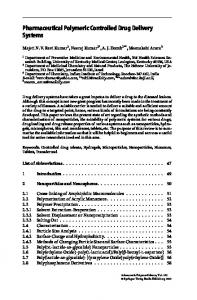
As described in the experimental section, a variety of resins were compounded with montmorillonite clays to determine whether CAMs improve the efficiency of exfoliation. In Figure 1, a TEM image of 5% of a nonexfoliated organically modified clay in PS is shown along with the corresponding x-ray diffraction pattern. In the TEM image the large dark area in the top center of the image has regularly spaced striations, which correspond to the edge-on view of the layered clay “Cloisite 20A”. The three distinct peaks in the XRD pattern arise from the scattering from planes that are 38 Å apart. This spacing is significantly larger than the 24 Å expected for the neat clay and indicates some degree of intercalation of the PS into the clay galleries.
5000 2500 0
5000
0 2500
2 4 6 o 2-Theta ( )
8
0 0
2 4 6 o 2-Theta ( )
8
50 nm
Figure 1. TEM image of 95/5 wt. % PS/20A clay. Inset: XRD pattern of the same sample.
TEM was performed using a transmission electron microscope operated at 200 kV, available under the trade designation "JEOL 200CX" from JEOL USA, Peabody, Massachusetts. Samples were cryo-ultra microtomed prior to imaging.
2.7
Rheological Characterization
The samples used for rheological characterization were prepared by feeding pelletized nanocomposite samples to a Mini-jector Model 45 injection molder available from MiniJector Machinery Corporation, Newbury, Ohio. The temperature of injection was 180 ºC with a pressure of 0.48 MPa. The rheological response of the nanocomposites was characterized using a TA AR 2000 rheometer. At a temperature of 200 °C and a frequency of 1 rad/s, three successive strain sweeps from 1-500% strain were applied to the material. The second sweep was performed immediately after the first. Between the second and the third sweeps the sample annealed for an hour at 200 °C with no applied strain. Wagener and Reisinger developed a technique similar technique to characterize exfoliation in polybutylene terephthalate. [8]
76
5000 2500 0 0
100 nm
2
4
6
8
o
2-Theta ( )
Figure 2. TEM image of 90/5/5 wt. % PS/CAM/20A clay. Inset: XRD pattern of the same sample. To improve the separation between the clay layers, we processed a compound of 90/5/5 wt.% PS/CAM/Cloisite 20A using the twin-screw extruder as described above. The morphology of this sample is presented in Figure 2. The TEM image shows distinct, separated clay layers on edge that are randomly oriented to each other. The inset is a XRD pattern taken at the same conditions as the one in Figure 1. The lack of features above 1.5° indicates that the
NSTI-Nanotech 2005, www.nsti.org, ISBN 0-9767985-1-4 Vol. 2, 2005
95/5 (PP/10A) 90/5/5 (PP/MAPP/10A) 90/5/5 (PP/CAM/10A)
Intensity (Counts)
4000 3000 2000 1000
for the PP/CAM/30B samples are consistent with exfoliated samples. Remarkably only 1 wt.% CAM in this formulation effectively exfoliates a clay modified with polar organic modifiers. We attribute this efficiency to the carefully designed interaction between CAM and the organic modifier that is possible with our materials.
Intensity (Counts)
2000
95/5 (PP/30B) 90/5/5 (PP/CAM/30B) 92/3/5 (PP/CAM/30B) 94/1/5 (PP/CAM/30B)
1500 1000 500 0 0
2
4 6 2-Theta (°)
8
10
Figure 4. XRD plot of nanocomposites made with various levels of CAM with PP and 30B clay. While the XRD patterns presented in Figures 3 and 4 indicate exfoliation, we would like to confirm the conclusion that formulations including CAM are exfoliated with a second technique. The TEM method used above in the PS samples, is more difficult to interpret in the case of semicrystalline samples such as PP. Instead we turn to rheology where we examine the hysteresis of the viscosity after strain sweeps. 2500 Viscosity (Pa s)
long range order observed in the neat clay has been eliminated by exfoliating the clay platelets. These complementary techniques of x-ray diffraction and TEM clearly show the change in morphology when a PS/clay composite is processed in the presence of a CAM. The amorphous polymer phase in a PS nanocomposite allows one to view the separated clay platelets and their random orientation to each other. For this reason, the PS resin composites were good starting points in our experiments. However, polyolefins are used in significantly higher volume in industry and in a wider variety of applications than polystyrene. Some of the desired improvements in polyolefin properties could be achieved with nanocomposites, including barrier properties, heat distortion temperature, and mechanical properties. In order to achieve these improvements with nanocomposites, the clay must first be exfoliated. The following data are our results in exfoliating clay with a CAM in a hot melt process for polypropylene. In Figure 3 we compare the ability of CAMs to exfoliate clay to the ability of random copolymers of maleated polypropylene (MAPP). For formulations made of the same composition of PP/additive/Cloisite 10A (90/5/5 wt.%), the formulation made with a CAM additive has no significant long range order in the XRD pattern. Both the control with no additive and the formulation with MAPP as an additive have significant peaks corresponding to a domain spacing of 18 Å. This is slightly smaller than the published value of 19.2 Å for Cloisite 10A.
1
2000
3
1500
2
1000 500 0
0 0
2
4 6 2-Theta (°)
8
10
Figure 3. XRD plot of nanocomposites made without additive, with CAM, and with maleated polypropylene. The lack of long-range order in the formulation with CAM suggests that the clay is exfoliated and randomly oriented by the melt processing method described above. In contrast samples without CAM do not exfoliate, or even intercalate with this processing method. The efficiency of CAMs at exfoliating clays in PP is further illustrated in Figure 4. In these formulations the clay Cloisite 30B is used at a 5 wt.% level while the CAM loading level is 5, 3, or 1 wt. %. The peak on the PP/30B curve corresponds to 18 Å, which is only slightly smaller than the reported value of 18.5 Å for neat Cloisite 30B. From this image the clay 30B does not exfoliate or intercalate in PP without CAM. The featureless curves
0
1
10 100 Strain (%)
1000
Figure 5. Strain sweeps at 200 °C of 95/5 wt. % PP/10A. (1) is the initial sweep. (2) is the second sweep. (3) is conducted after a 60 min anneal at 200 °C. In Figure 5, three strain sweeps performed in succession on the sample 95/5 wt.% PP/10A (see Figure 3) are plotted on the same graph. The initial strain sweep shows the highest viscosity and pronounced shear-thinning behavior at strains above 60%. The second sweep, performed immediately after the first finished, shows slightly lower viscosity at low strains, a plateau region at intermediate strains, and pronounced shear-thinning at strains higher than 60%. The sample was annealed at 200 °C for 60 minutes between the second and third sweeps. The viscosity of the third sweep again shows a plateau
NSTI-Nanotech 2005, www.nsti.org, ISBN 0-9767985-1-4 Vol. 2, 2005
77
Viscosity (Pa s)
2500 2000
1
1500
3
1000 2
500 0 0
2500 2000 1500 1000 500 0
1
10 100 Strain (%)
1000
Figure 7. Strain sweeps at 200 °C of 90/5/5 wt. % PP/CAM/Na+. (1) is the initial sweep. (2) is the second sweep. (3) is conducted after a 60 min anneal at 200 °C.
1 3
2
0
1
10 100 Strain (%)
1000
Figure 6. Strain sweeps at 200 °C of 90/5/5 wt. % PP/CAM/10A. (1) is the initial sweep. (2) is the second sweep. (3) is conducted after a 60 min anneal at 200 °C. The strong hysteresis observed in Figure 6 for the sample containing CAM, which has a XRD pattern consistent with exfoliation, suggests that the platelets are aligned during the first strain sweep. At the beginning of the second strain sweep low viscosity suggests that the platelets are still aligned, but begin to re-randomize over the course of the second sweep. The platelets are re-aligned at high strains in the second sweep, but the one-hour annealing period allows them to re-randomize to a greater extent. This results in an intermediate plateau viscosity at low strains. In contrast the sample present in Figure 5, which has a XRD pattern consistent with non-exfoliated clay (see Figure 3), shows little hysteresis and insignificant drop in viscosity. The clays presented to this point have all been organically modified with as much as 30% of organic modifier. Some applications will call for pure inorganic clay, and we believe that the physical properties of claybased nanocomposites will be improved using natural clays. This approach is challenging because natural clays have smaller domain spacing and less flexibility in terms of what chemical functionality the CAM can interact with at the surface. An added complication in determining the exfoliation efficiency of Na+ clay nanocomposites is that the clay has a weak scattering factor yielding weak peaks in XRD. Thus the absence of peaks in a XRD pattern with Na+ Cloisite cannot be used as evidence of exfoliation. In Figure 7 we show a strain hysteresis plot of 90/5/5 wt.% PP/CAM/Na+. As in the case of the exfoliated system 78
shown in Figure 6, the first two strain sweeps show marked deviation. The third shows recovery of the viscosity plateau and increased viscosity compared to the second sweep. As shown in Figure 6, this type of rheological trace is consistent with an exfoliated system. Viscosity (Pa s)
viscosity up to about 60% strain. This plateau value is slightly lower than the value in the initial strain sweep. In Figure 6, the sample of 90/5/5 PP/CAM/10A is probed with the strain test. The first strain sweep has a plateau region slightly lower than the sample in Figure 5, with pronounced shear-thinning behavior above strains of 60%. The second strain sweep shows viscosities at low strains that are comparable to the low viscosities seen at the highest strains. At intermediate strains the viscosity in the second sweep recovers to a value less than half that of the initial viscosity. Strains above 60% again show shear thinning behavior. After annealing the sample for one hour, the viscosity again shows a plateau at low strains, with strong shear-thinning behavior at strains above 60%.
The exfoliation of natural clay in polyolefin by melt processing is a significant advance and is made possible by the flexibility inherent in CAM materials. In addition our ability to characterize Na+ clay nanocomposites by the rheological method described above allows us to explore new applications with different resins. In the future we will continue to probe the physical property enhancements afforded by nanoclay exfoliation in a variety of resins.
REFERENCES [1] A. Okada, M Kawasumi, A Usuki, Y Kojima, T Kurauchi, O Kamigaito MRS Symposium Proceedings, Pittsburg, vol 171; 1990. 45-50. [2] DJ Greenland J. Colloid Science, vol 18; 1963. 647664 [3] P Aranda, E Ruiz-Hitzky Chem Mater, vol. 5; 1993. 1395-1403. [4] JJ Cernohous, S Papp, NR Granlund, JM Nelson, RE Marx, JG Linert. In US 20040254268 Unitied States, 2004. [5] Nelson, J. M.; Marx, R.E.: Hanley, K.J.: Cernohous, J. J. Jones, T.D.: McNerney, J. M.; In US 20040024130 United States, 2004. [6] Nelson, J. M.; Marx, R.E.: Cernohous, J. J.: McNerney, J. M.; In US 20040023398 United States, 2004. [7] Nelson, J. M.; Cernohous, J. J.; Annen, M. J.; McNerney, J. M.;Heldman, B.; Ferguson, R. W.; Higgins, J. A. In US 6,448,353 United States, 2002. [8] R Wagener, TGJ Reisinger Polymer, vol. 44; 2003. 7513-7518.
NSTI-Nanotech 2005, www.nsti.org, ISBN 0-9767985-1-4 Vol. 2, 2005