Keywords: paper architecture, pop-up, computer art, planar layout ... many forms,
such as greeting cards and desktop decorations, and ... to the design of cut and
fold patterns on the paper (called a planar ... foldability problems than traditional
origami, some of which we ...... Computing length-preserved free boundary for.
Popup: Automatic Paper Architectures from 3D Models Xian-Ying Li1 Chao-Hui Shen1 Shi-Sheng Huang1 Tao Ju2 Shi-Min Hu1 TNList, Department of Computer Science and Technology, Tsinghua University, Beijing 2 Department of Computer Science and Engineering, Washington University in St. Louis
1
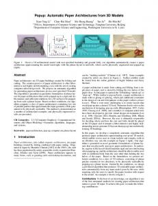
Figure 1: Given a 3D architectural model with user-specified backdrop and ground (left), our algorithm automatically creates a paper architecture approximating the model (mid-right, with the planar layout in mid-left), which can be physically engineered and popped-up (right).
Abstract Paper architectures are 3D paper buildings created by folding and cutting. The creation process of paper architecture is often laborintensive and highly skill-demanding, even with the aid of existing computer-aided design tools. We propose an automatic algorithm for generating paper architectures given a user-specified 3D model. The algorithm is grounded on geometric formulation of planar layout for paper architectures that can be popped-up in a rigid and stable manner, and sufficient conditions for a 3D surface to be poppedup from such a planar layout. Based on these conditions, our algorithm computes a class of paper architectures containing two sets of parallel patches that approximate the input geometry while guaranteed to be physically realizable. The method is demonstrated on a number of architectural examples, and physically engineered results are presented. CR Categories: I.3.5 [Computer Graphics]: Computational Geometry and Object Modeling—Geometric algorithms, languages, and systems; Keywords: paper architecture, pop-up, computer art, planar layout
1
Introduction
Paper architectures, also called origamic architectures, are paper buildings created by folding combined with paper cutting. Originated in Japan by Masahiro Chatani [1987] in the 1980’s, the craft has been popularized by artists around the world, in particular Bianchini, Siliakus and Aysta [2009]. Paper architecture appears in many forms, such as greeting cards and desktop decorations, and
can be “startling realistic” [Chatani et al. 1987]. Some examples created by artists are shown in Figure 2. Further exhibits could be found from the online galleries of Ingrid Siliakus and Gerry Stormer. A paper architecture is made from cutting and folding from a single piece of paper, and is stored by folding the two halves of the paper close. As the paper is opened, the 3D building “stands-up” or “pops-up”. While similar to pop-up books, a paper architecture is made with no gluing or splicing, which puts additional constraints to the design of cut and fold patterns on the paper (called a planar layout). What is even more challenging is to create layouts that would pop-up into a desired 3D look. Numerous books exist on the mechanism of designing pop-up crafts [Birmingham 1997; Carter 1999; Cheong et al. 2009], and a number of computer-aided tools have been developed to provide virtual design environments [Lee et al. 1996; Glassner 2002; Hendrix and Eisenberg 2006; Mitani and Suzuki 2004a]. However, the user is ultimately responsible for deciding where and how the cuts and folds should be placed on the 2D paper, and it remains a labor-intensive and highly skilldemanding task to generate 2D layouts that pop-up into realistically looking 3D buildings. In this paper, we develop a completely automatic algorithm that produces paper architectures approximating user-given 3D models, which enables novice users to create realistic and complex crafts in an effortless way (see the example on Figure 1 right). Our algorithm is grounded on novel geometric formulations of planar layouts that can physically pop-up to paper architectures. In particular, regions in the layout should maintain rigid and non-intersecting when popping-up, and the architecture should be able to stably erect with no additional help from the user other than holding the two halves of the paper. Based on the formulation, we present sufficient conditions for a class of 3D surfaces, consisting of planar patches oriented in two directions, to be physically realizable by popping-up a planar layout. Guided by the conditions, we design a grid-based algorithm that produces 3D realizable paper architectures automatically from any input model given by the user, while requiring only the users to specify the paper location with respect to the model. An example is shown in figure 1. Contributions To the best of our knowledge, our algorithm is one
of the first automated methods for creating paper architecture that mimics a given 3D input. To achieve this goal, we make the following contributions:
(a) Amsterdam Central Station
(b) Statue of Liberty
(c) Bellesguard Tower
(d) Himeji Castle
Figure 2: Paper Architecture by Masahiro Chatani, Marivi Victoria Garrido Bianchini & Ingrid Siliakus. • We present a formal, geometric formulation of planar layouts that can rigidly and stably pops-up to a paper architecture (Section 3). • We present sufficient conditions for a class of 3D surfaces, consisting of patches oriented in either one of two directions, to be realizable by popping-up a planar layout in a rigid and stable way (Section 4). • We present an automatic algorithm that generates paper architectures and their planar layouts that approximate any given 3D models with guaranteed realizability. (Section 5).
2
Related work
Paper crafting Different types of paper crafting has been studied in the mathematical and computational setting. Here we will briefly review some major forms.
Origami is the traditional Japanese art of paper folding. Typically, origami is folded-flat (meaning the model can be flattened without being damaged) [Hull 1994] using a single piece of paper, and no cutting or gluing is used. Folding algorithms and foldability for origami has been extensively studied in the computational geometry community, and we point readers to a recent book by Demaine and O’Rourke [2007]. More recently, Tachi [2009] proposed an algorithm to automatically generate origami design for arbitrary polyhedral surfaces. Curved folding has also been considered [Kilian et al. 2008] based on analysis of developable surfaces. By allowing cutting, paper architecture presents a different set of folding and foldability problems than traditional origami, some of which we hope to address in this work. Strip modeling is concerned with representing 3D models as paper strips, or piece-wise developable surfaces. Mitani and Suzuki [2004b] proposed a method for approximately making general surfaces by paper-strips. Their algorithm is powered by mesh simplification, which is a well-studied but still active topic [Garland and Heckbert 1997; Cohen et al. 1998; Wei and Lou 2010]. Alternative methods also have been proposed in [Shatz et al. 2006] and [Massarwi et al. 2007]. With the use of cutting and splicing, strip modeling can achieve complex and even knotted geometry that is otherwise infeasible in other paper art forms. Paper-cutting is a Chinese folk art that cuts out stylistic patterns and figures from a piece of paper. A simple and efficient algorithm for automatic paper-cutting given input images was proposed in [Xu et al. 2007]. Extensions to 3D paper-cuts and interactive design of animations with paper-cuts have also been considered [Li et al. 2007].
Computational paper architecture Unlike other paper art forms,
algorithmic solutions for paper architecture have been scarce. Most computational work revolves around creating computer-aided environment for designing pop-up crafts. Glassner introduced a system in [Glassner 2002] where users can interactively design single-slit and V-fold, two basic skills of pop-up card. A similar system is the Popup Workshop for children [Hendrix and Eisenberg 2006]. However, self-intersections may happen in these systems and they have to be resolved by users. Mitani and Suzuki [2004a] proposed a CAD system for paper architecture design, which ensures the geometric validity of the output and the foldability of the planar layout by their construction mechanism. In addition, a pop-up condition is proposed that checks whether a layout can be erected when the paper opens. However, this condition is not automatically guaranteed by their system, and hence needs to be resolved by the user in a trial-and-failure manner. Note that, in general, deciding whether a given pop-up craft can be opened or closed is a NP-hard problem [Uehara and Teramoto 2006]. In our work, we proposed a sufficient condition that the layout can erect in a stable manner as the paper opens, and further provides an automatic algorithm that guarantees the satisfaction of the condition in the output. There are few automated methods for creating pop-up crafts or paper architectures. Hara and Sugihara [2009] considered a 2D version of the pop-up problem (given a polygon as the desired popupped shape) and proposed an automated solution involving polygonal subdivision. However, the method requires gluing multiple paper pieces, which is not allowed in paper architectures. The only previous work we know of that produces paper architecture from 3D models is by Mitani et al. [2003] (in Japanese). Like our method, their work considers voxel grid to construct the pop-up surfaces. However, their algorithm creates 3D buildings with simple, stair-stepping appearances and lacking guarantees of pop-up or stability. In contrast, we propose a robust algorithm, grounded on geometric formulations of foldability and stability, that produces results closely resembling the input models. Note that stability of architectural models has also been considered by Whiting et al. [2009] in procedural modeling, although the modeling primitives there and hence the stability conditions are very different from ours. Shape abstraction Approximating a 3D model by a paper archi-
tecture is a stylistic way of abstracting the shape. Previous work on shape abstraction is mostly based on segmentation of surface patches [Lai et al. 2006; Shamir 2008; Lai et al. 2009] and approximating them with simpler primitives such as quasi-developable or nearly-flat patches [Julius et al. 2005; Yamauchi et al. 2005; Wang 2008; Mehra et al. 2009]. The result of our method can be considered as a special type of abstraction using planar patches in two directions, parallel to either one half of the paper, that have additional physical properties (e.g., being able to pop-up from the plane).
(a) (a)
(b)
Figure 3: A foldable PLPA (a) with cut lines (black) and fold lines (red and blue respectively for mountain and valley folds), and a folded PLS at 90◦ fold angle (b).
3
Formulations
A paper architecture is created from a single piece of paper by cutting and folding. The planar layout of such a paper architecture consists of a set of cut lines and fold lines that divide the paper into various regions. Typically, there are two outer regions, called backdrop and ground, that meet at a central fold. When the user folds the central fold by moving the backdrop and ground, the rest of the regions “pop-up” as a result of folding along the fold lines. Our ultimate goal is to device computational algorithms to construct planar layouts that can be physically popped-up. To guide the algorithm design and show its correctness, we first present geometric formulations of planar layouts, particularly those that can be popped-up in a physically realistic manner.
3.1
Layouts
Planar layouts for paper architecture, as well as their folded results, can be generally considered as a kind of 3D surface with linear components. Specifically, we define:
(b)
(c)
Figure 4: A parallel PLS stable with respect to the backdrop and ground (a), and one that is not stable (b) and can be folded to (c) while maintaining the rigidity of the patches. assumption, we define foldability generally as a relation between two PLS: Definition 3 Given two PLS S, T , S is said to be foldable from T if there exists a continuous mapping f : T → S such that: 1. f (0) = T , f (1) = S 2. For any t ∈ [0, 1], f (t) is a PLS that maintains the rigidity and continuity of patches in T . The mapping f is called the fold transform from T to S. We are interested in PLPAs that can open and close “all the way”. Let fold angle be the outer angle of the central fold in a PLPA or any PLS folded from a PLPA (e.g., the fold angle of a PLPA is zero). Note that, strictly speaking, a PLPA cannot close completely (e.g., at fold angle 180◦ ) by our definition of foldability, as the backdrop and ground are not allowed to overlap. We therefore formulate a foldable layout as: Definition 4 A PLPA T is said to be foldable if there is a fold transform f from T during which the fold angle increases monotonically from 0 to 180◦ − � with arbitrarily small �. This transform f is called the pop-up transform of T , and any f (t) for t ∈ [0, 1] is called popup-foldable.
Definition 1 A piece-wise linear surface (PLS) is a collection of planar, non-intersecting and non-overlapping patches where neighboring patches share common straight edges.
For example, the PLPA shown in Figure 3 (a) is foldable, and a popup-foldable surface at 90◦ fold angle is shown in (b).
Definition 2 A planar layout for paper architecture (PLPA) T is a PLS where
3.3
1. All patches in T are co-planar, 2. T forms a rectangular domain with possible holes, and 3. There exist two patches, called backdrop and ground, that touch the outer rectangular boundary and share edges along the mid-line of the rectangle. An example of a PLPA is shown in Figure 3 (a). In a PLPA, we call common boundaries between neighboring patches fold lines (red and blue lines in the picture), and the rest of the patch boundaries as cut lines (black lines in the picture). In particular, we call the fold lines between the backdrop and ground as the central fold.
3.2
Foldable layouts
Obviously, not all PLPA can be folded up. To define foldability, we make the key assumption that the paper is made up of rigid materials (e.g., metal) except at the boundary of patches (e.g., hinges). Furthermore, we assume the paper has zero thickness. These two assumptions help us to formulate foldability, as well as realizability, as simple geometric properties. Note that the same assumptions are made in rigid origami [Belcastro and Hull 2002]. With the rigidity
Realizable layouts
A foldable PLPA as defined above may not be able to “pop-up” as the user opens or closes the ground and backdrop. For example, the PLPA may contain pieces disconnected from the ground or backdrop that needs extra support to hold them in place. Also, the pop-up transform may require external forces along the fold lines in order to crease them in practice. Ideally, we would to create stable paper architecture where the pop-up transform does not require additional forces other than opening and closing the backdrop and ground by the user, and the paper at each stage during the transform is able to hold steady when the backdrop and ground are fixed. We can define realizability based on the same rigidity assumption we made above. Intuitively, a PLS that can hold steady when some patches are fixed is one that cannot be folded to another state while keeping the fixed patches unchanged. Also, if the PLPA at each time point of a continuous folding process is stable with respect to the backdrop and ground, then no external forces would be required to get to the next time from a previous time other than moving the backdrop and ground. More formally, we define: Definition 5 Given a PLS S and a subset of patches P ⊂ S, S is said to be stable with respect to P if there is no other PLS S 0 6= S that is foldable from S via a fold transform f , where P keeps stationary during f .
For example, the staircase example in Figure 4 (b) is not a stable PLS, as it can be collapsed to the shape in (c) continuously without affecting the rigidity of the patches. In contrast, the examples in Figure 3 (b) and Figure 4 (a) are. Finally, we define a realizable layout as: Definition 6 A PLPA T is said to be realizable if it is foldable, and there is a pop-up transform f of T such that any f (t) for t ∈ [0, 1] is a PLS stable with respect to its backdrop and ground. This transform f is called a realizable pop-up transform, and any f (t) for t ∈ [0, 1] is called popup-realizable.
4
Sufficient conditions
The goal of our algorithm is to create realizable planar layouts that approximate a given 3D model when folded. We therefore need to answer the inverse question: given a 3D surface (e.g., a PLS), is it pop-up realizable? In this paper, we consider a special type of PLS for which we are able to derive sufficient, computable conditions of realizability. These conditions will guide our algorithm design and ensure the correctness of the results. Definition 7 A parallel PLS Sv,w is a PLS where the normal direction of each patch is either v or w, which are unequal unit vectors. For example, the examples in Figure 3 (b) and Figure 4 (a,b) are all parallel PLSs where v, w are orthogonal. Note that most paper architecture falls into this class, such as the ones shown in Figure 2. We first show conditions for popup-foldable parallel PLSs: Proposition 1 Consider a parallel PLS Sv,w , and let U = v × w, V = w × U , and W = U × v (as shown in Fig 3 (b)). If parallel projection of Sv,w in the direction of V + W onto a plane with normal v results in a PLPA, then Sv,w is popup-foldable. Proof: Consider the parallel projection T on the plane containing the origin. We will show that T is a foldable PLPA by constructing a pop-up transform from T via Sv,w . We can express any point x on Sv,w as: x = (xU , xV , xW ) · (U, V, W )
(1)
Note that U, V, W are linearly independent, hence the decomposition is unique. Consider the following continuous mapping f where f (t) for t ∈ [0, 1] consists of points: x(t) = (xU , xV , xW ) · (U, V (tπ), W )
(2)
for all points x ∈ Sv,w . Here, V (α) = w(α) × U where w(α) is a vector rotated from v around U by α degrees. We show several properties of f : • f (0) = T . In fact, for any point x ∈ Sv,w , x(0) lies on the plane with normal v containing the origin, and x − x(0) = xV (V + W ). • f (t) = Sv,w for t = θ/π where θ is the angle between v, w. • f (t) is intersection-free for any t ∈ [0, 1), due to the uniqueness of the decomposition (when t > 0) and the nonintersection property of a PLPA. • The transform f maintains the rigidity of the patches in S. In fact, for any two points x, y on a same patch in Sv,w with normal v (or w), x(t), y(t) will lie on a common plane orthogonal to v (or w(tπ)), and kx − yk = kx(t) − y(t)k for any t ∈ [0, 1].
As a result, f is a valid pop-up transform from T via Sv,w , and Sv,w is popup-foldable. � Note that the conditions in Proposition 1 can be checked computationally given a parallel PLS. In our algorithm, we will construct a specific class of parallel PLS that satisfies these conditions naturally by the construction process. Making one step further, we have the following sufficient condition for a parallel PLS that can be rigidly and stably popped-up: Proposition 2 A parallel PLS Sv,w satisfying Proposition 1 is popup-realizable if it further satisfies the following condition: there exists an ordering of patches in Sv,w = {p1 , . . . , pn } such that p1 , p2 are the backdrop and ground respectively, and for any k ∈ [3, n], either: 1. pk is connected to two parallel, non-coplanar patches pi , pj where i, j < k, or 2. pk is connected to pk+1 , and pk , pk+1 are respectively connected to some pi , pj where i, j < k and pi , pk+1 are noncoplanar. Proof: We will first show that a parallel PLS S meeting the two conditions above is stable with respect to p1 , p2 . We start with two observations. First, a rigid planar patch will be fixed if two non-colinear boundary edges are fixed. Second, consider two rigid planar patches pa , pb sharing a common edge e. Then pa is fixed if there is an edge ea of pa and an edge eb of pb such that e, ea are non-colinear, and ea , eb are fixed. With these observations, it is easy to show that the patches of Sv,w are stable by induction. By Proposition 1, Sv,w can be folded from a PLPA T by the popuptransform f defined as in Equation 2. Note that the two conditions here still hold during the transform, which preserves the connectivity and parallel relations among patches. Therefore, T is a realizable PLPA and Sv,w is popup-realizable. � For example, the parallel PLS in Figure 4 (a) is popup-realizable according to the above conditions, using the ordering of patches marked in the figure. In contrast, no such ordering can be found on the PLS in Figure 4 (b).
5
The algorithm
The input of our method is a 3D model with user assigned backdrop and ground plane locations. The output of the algorithm is a paper architecture represented as a popup-realizable, parallel PLS that approximates the input model. In this paper, we focus on parallel PLS with 90◦ fold angles, as such PLS encompasses a large range of models including urban architectures, though the algorithm can be easily adapted to other fold angles. To best capture the model geometry while fulfilling the conditions stated in the previous section, we proceed in three steps (illustrated in Figure 5): 1. Popup-foldable surface: First, we compute an initial, parallel PLS approximating the input model and consisting of orthogonal faces on a Cartesian grid. This initial PLS is referred to as the visible PLS. The construction process ensures the popup-foldability according to Proposition 1 (Figure 5 (b)). 2. Popup-realizable surface: Next, we modify the visible surface to further meet the realizability condition in Proposition 2 while maintaining foldability. This is achieved using a greedy, region-growing algorithm (Figure 5 (c)). 3. Geometric refinement: Finally, the zig-zag boundaries of the patches in the Cartesian surface computed above is improved while maintaining realizability (Figure 5 (d)).
(a)
(b)
(c)
(d)
Figure 5: Algorithm flow: input 3D model with user-specified backdrop and ground planes (a), the visible PLS consisting of Cartesian grid faces (b), a modified, popup-realizable PLS and its layout (c), and the final PLS and its layout after geometric refinement (d).
5.1
Computing the visible surface
The input of the algorithm is a 3D model represented as a triangular mesh (could be either open or closed), and the user-specified backdrop and ground planes. As we focus on 90◦ fold angle, we ask these two planes to be orthogonal to each other. Without loss of generality, we assume that the two planes are squares that lie respectively on the XZ and XY planes with the central fold lying on the positive X axes, as shown in Figure 5 (a). To construct a parallel PLS at 90◦ fold angle, we utilize the axesaligned faces of a Cartesian grid. We construct a N × N × N uniform grid with the backdrop and ground planes as its two sides, and identify all cubes in the grid that are intersected by the input mesh. We call model faces as the set of all grid faces orthogonal to the Y or Z axes that are contained in the identified cubes or lying on the backdrop and ground planes. We will select a subset of these faces to form a popup-foldable PLS. To fulfill the conditions in Proposition 1, the key requirement is that the projection of the parallel PLS Sv,w along a particular direction forms a non-intersecting set. In our case, v = (0, 0, 1) and w = (0, 1, 0), and that projection direction is (0, 1, 1). Since the pop-up is typically viewed from the outside, we simply take all model faces that are “visible” in the (0, −1, −1) direction when viewed from outside the grid. These faces are called visible faces, as shown in Figure 5 (b). Note that this view direction, combined with the uniform arrangement of the grid, ensures that the projection of visible faces are disjoint. As the outer parts of backdrop and ground planes are also visible faces, their projection will form a rectangular domain. Hence the set of visible faces is a popupfoldable PLS, which we refer to as the visible PLS.
Figure 6: A lateral sketch illustrating the notations used in Section 5.2: S0 (blue) is the visible PLS, S (red) is our desired popuprealizable PLS, b is a base face, and H(b) (stairs between the dotted lines) are the candidate faces of b, which include S0 (b) and S(b) lying respectively on S0 and S. PLS S and the visible PLS S0 along the view direction as: E(S, S0 ) =
X
kS(b), S0 (b)k
(3)
b∈B
where B is the set of all base faces, S(b), S0 (b) ∈ H(b) are respectively the face on S and S0 that projects onto b (see Figure 6), and k·, ·k is the Euclidean distance between the centers of two faces.
The visible PLS is a popup-foldable PLS that “wraps” around the outside of the model. To further ensure realizability, we will construct a PLS that maintains the shape and foldability of the visible PLS while meeting the additional conditions in Proposition 2.
We adopt a greedy, region-growing approach to construct a popupfoldable PLS S that minimizes the above error term while satisfying the patch-ordering condition in Proposition 2. We first include in S the ground and backdrop patches, which consist of visible faces respectively on the ground and backdrop plane that are connected to the outmost ring of faces on each respective plane (see Figure 7 (b)). We then work ourselves inwards, each time either adding faces to existing patches (as in Figure 7 (e)) or adding new patches of faces that are connected to existing patches (as in Figure 7 (c,d)) in one of the ways allowed by the conditions in Proposition 2.
To do so, we first present means to generate a family of popupfoldable PLS and to measure their error with respect to the visible PLS. Let us call each grid face b on the ground and backdrop plane a base face, and all grid faces that project onto b along (0, −1, −1) as its candidate faces, denoted as H(b). Visually, H(b) form a “staircase” with alternating normals in Y or Z direction, as shown in Figure 6. By the same argument above, any PLS consisting of exactly one candidate face per base face is a popup-foldable PLS. We can measure the discrepancy between any such popup-foldable
Specifically, we maintain a priority queue that contains two types of elements associated with costs. Let us call a base face b visited if b has a candidate face in S, and unvisited otherwise. A queue element can be an unvisited base face adjacent to a visited base face, or a path of unvisited base faces with the same X coordinate that connect between two visited base faces. For the first type, the cost of the base face is the lowest error of any of its candidate face, that is parallel and adjacent to an existing face in S (e.g., the two violet faces in Figure 7 (e) are parallel and adjacent to existing faces
5.2
Computing a popup-realizable surface
(a)
(b)
(c)
(a)
(b)
(d)
(e)
(f)
(c)
(d)
Figure 7: Computing a popup-realizable PLS by region growing: the visible PLS (a), initial ground and backdrop patches (b), three steps in the growing process (c,d,e) where either new patches are added (c,d) or new faces are added to existing patches (e), and the final popup-realizable PLS (f). already on S). For the second type, let the path of base faces be {b1 , . . . , bm } where only b1 , bm are visited. We consider all paths, each consisting of one candidate face S(bi ) per base face bi for i ∈ [2, m − 1], that connect to end faces S(b1 ), S(bm ) following one of the patterns in Figure 8 top (e.g., the violet paths in Figure 7(c,d)). The cost of the base faces path is the lowest error among all candidate paths, if it exists, or infinity otherwise. At each iteration, the element(s) with lowest cost is(are) removed from the queue, the candidate face(s) realizing that cost is(are) added to S, and the queue is updated accordingly. The algorithm terminates when the queue is empty. Note that termination of this algorithm is guaranteed, since the first type of element (that is, adding a new face to an existing patch) will always be associated with a finite cost. Also, the path patterns in Figure 8 top guarantee that any new patch added to S (consisting of new faces that are not co-planar with neighboring faces already in S) satisfies the conditions in Proposition 2, and hence S is popuprealizable after termination. An example result of the algorithm is shown in Figure 5 (c).
5.3
Figure 8: Possible paths connecting two orthogonal (a) or parallel (b) end faces that are considered by our algorithm when finding the lowest error of a path-type queue element (see Figure 7 (c,d) for example paths of these two types). No path is allowed if the top end face (one with higher center Z coordinate) is to the front (with higher center Y coordinate) of the bottom end face, as in (c,d). make sure they project onto the modified cut lines. Specifically, for every vertex p on the cut line, we will give it a new location p0 on the XY plane, while moving the images of p along the planes of their respective patches so as to project onto p0 . This is easily done as follows: let (∆x, ∆y, 0) = p0 − p, we will move a boundary point q projected to p either by the same vector (∆x, ∆y, 0), if q is on a patch parallel to the XY plane, or by (∆x, 0, ∆y) otherwise. Note that if q is contained in both vertical and horizontal patches (e.g., projecting to a point on the fold line in the planar layout), q may only move in the X direction. To ensure feasible movement, and furthermore avoid self-intersections during the process, we restrict the movement of each vertex p on the cut line within a “safe zone”. As shown in Figure 9 right, the shape of a safe zone is a square if the vertex is not contained in a fold line, and a line segment otherwise. Note that any location of the vertex in the safe zone would yield new patch boundary locations that maintain the realizability of the surface.
Geometric refinement
The result of the first two steps is a surface that can be popped-up from a planar layout in a rigid and stable manner. However, the use of grid faces result in jagged patch boundaries that is both unpleasing for viewing and difficult for cutting. In the last step, we perform a simple smoothing procedure that alleviates such jaggedness while maintaining the realizability of the surface. Consider the planar layout of our realizable PLS S as its projection in the direction (0, 1, 1) onto the XY plane. The cut and fold lines on this layout lie on grid lines of an extended Cartesian grid (an example is shown in Figure 9 left). In particular, the cut lines (drawn black in the picture) consist of those grid edges (cut edges) on the XY plane shared by two grid faces that are projected from two nonadjacent faces in S. A vertex p on the cut line is projected from boundary points of two or more patches. We call these boundary points the images of p. To achieve smoother patch boundaries, we will smooth out the cut lines on the planar layout while adjusting the patch boundaries to
Figure 9: A portion of the planar layout of a popup-realizable PLS (left), and the safe zones around vertices on the cut lines for cut line smoothing (right). To smooth the cut lines on the planar layout, we adopt the standard iterative Laplacian-based scheme that moves each vertex towards the center of its neighbors while restricting the movement to its safe zone. To avoid fluctuation, we move vertices one at a time instead of simultaneously at each iteration. Figure 5 (d) shows an example of result after smoothing.
(a) Cerrito Church, Uruguay
(b) Alte Oper Frankfurt
(c) Jade Belt Bridge, China
(d) Lincoln Memorial
Figure 10: Paper architectures and their planar layouts computed from 3D models (in thumbnails) obtained from Google 3D Warehouse.
6
Results
We showcase a gallery of our results in Figure 10, and some other results in Figure 1,5,12,13. All models are obtained from Google 3D Warehouse, and a grid resolution N = 128 is used during voxelization. Observe that the resulting paper architectures mimic well the input geometry. Many detailed structures are captured, such as the pillars of the Hanging Garden (see Figure 1) and the spire on New York Life Building (see Figure 13). Since our algorithm is restricted to paper architectures containing parallel patches in two orientations, the vertical and horizontal faces of the model are best preserved while sloped and curved surfaces are approximated by staircase-looking folds (such as the Eiffel Tower in Figure 5, the Jade Belt Bridge and the Cerrito Church in Figure 10). Note that such folds also appear in manual works of paper architecture (such as the curved dome in Himeji Castle in Figure 2).
Figure 11: Actual paper architectures made according to the planar layouts computed by our algorithm. Our algorithm guarantees the realizability of the results, that is, each paper architecture can be rigidly and stably popped-up from
their planar layouts. To demonstrate realizability, we show in Figure 11 two actual paper craft made according to the planar layouts shown in Figure 1 and Figure 5. Their popping-up process is captured in the accompanying video.
Figure 12: Paper architectures of Mayan Pyramid with two different backdrop and ground settings.
Figure 13: Paper architectures of NewYork Life Building before (left) and after (right) editing and hollowing. Note that the two sides are edited to be oblique while windows and peace doves are hollowed out. Our method is also very efficient. All examples shown in the paper are computed within one second of time on an Intel Core 2 Duo 3GHz computer with 4GB RAM. As the method offers immediate
feedback to the users, it makes it possible to perform interactive editing on the results. Although making a fully-featured interactive design tool is beyond the scope of this paper, a number of editing operations can be easily performed within our current framework. First, the user can modify the location of the backdrop and ground planes. Example results with different choices of the planes are shown in Figure 12. Second, the user may adjust the shape of the cut lines on the planar layout, much in the same way as our smoothing step, to achieve more stylistic patch boundaries. Third, the user can select regions on the planar layout to “cut out”, achieving hollow effects. These two edits are demonstrated in Figure 13, where stylistic windows and birds are created by cutting out and slopes are created on the building sides by adjusting the cut lines.
7
Conclusion and discussion
In this paper, we presented geometric formulations of paper architecture, particular focusing on the rigidity and stability of the popup process which is critical for creating such crafts in reality. Based on the formulations, we are able to give sufficient conditions for a class of 3D surfaces to realizable via pop-up, and further develop a novel algorithm that automatically converts a 3D model to a paper architecture with little user input. The algorithm is robust in producing realizable paper architecture and is computationally efficient. A gallery of examples are presented using architectural models, and physical crafts are made according to the algorithm results. Limitations While the current algorithm design focuses on realiz-
ability, it may not achieve a completely satisfactory “appearance”, especially when compared with crafts manually designed by skilled artists (see Figure 2). Note that extreme abstraction is often used in these crafts, such as the Statue of Liberty in Figure 2, which is visually appealing. Achieving results that appeal to human perception is a fundamentally challenging task, which has been continuously addressed in other areas in graphics such as shape segmentation and non-photorealistic rendering.
(a) A floating cube
Figure 14: cases.
(b) A half-torus
Results of our algorithm (bottom) for two extreme
Our algorithm performs best when the input model contains mostly horizontal and vertical planes, and is well-supported by the ground and backdrop pieces (which is true for typical architectural models). When these conditions are not met, the algorithm may significantly alter the input shape to achieve realizability. In Figure 14, we demonstrate two extreme cases, a floating cube and a half-torus.
(a) The bunny
(b) The teapot
Figure 15: Results of our algorithm for non-architectural models.
In the first case, the algorithm “pushes” the cube towards the corner to make it connected to the backdrop and ground pieces. In the second case, the caved-in space in the middle of the torus is ”filled” so that it can be stably popped-up. Figure 15 further shows two organic models, and note that the results, although resembling the inputs, contain large distortions and miss some important features (e.g., the head of the bunny). A more faithful reproduction of these general shapes would possibly require more than a single piece of paper (as in pop-up books). Future work Our work opens up a number of interesting venues
of future research that would extend the current work in both theoretical and algorithmic directions. On the theoretical end, there is ample room to improve and generalize the stability and foldability criteria. For example, the current stability conditions (Proposition 2) are only sufficient, hence possibly precluding some stable configurations. A condition that is both sufficient and necessary would be ideal, which can be also used to check if a given PLS (e.g., constructed by other computer-aided tools) is stable. Furthermore, generalizing the foldability and stability conditions to nonparallel PLS could allow us to better represent tilted planes in the input model. Taking one step further, one could consider a more physically realistic problem where physical properties of the paper, such as its thickness, mass, and flexibility, are taken into account. To this end, it would be interesting to investigate how our definition of planar PLS can be relaxed to allow slit spaces between patches, and how foldability and stability should be re-formulated for nonrigid patches with weights. On the algorithmic end, we would like to first explore more optimal ways for finding realizable PLS than the current greedy patchgrowing strategy (Section 5.2). Secondly, the geometry refinement step (Section 5.3) can be improved by considering the original shape of the model for better preservation of model features. Furthermore, as mentioned above, it would be interesting to explore how to incorporate abstraction rules used by artists in our algorithm to produce more artistic results. Last but not least, while the current work considers little user input, our next step is to design an integrated interactive system with more flexible user controls while maintaining the guarantees of realizability. Such controls could take the form of adjusting level-of-detail in different parts of the model, editing patches on the paper architecture, and interactive creation of new folds (e.g., single-slits and v-folds).
Acknowledgements We thank Guo-Xin Zhang and Ying-Hua Ai for the inspiring chats with us, and all the reviewers for their helpful comments. This work was supported by the National Basic Research Project of China (Project Number 2006CB303102), the Natural Science Foundation of China (Project Number U0735001) and the National High Technology Research and Development Program of China (Project
Number 2007AA01Z336), and NSF grant IIS-0846072.
References B ELCASTRO , S., AND H ULL , T. 2002. Modelling the folding of paper into three dimensions using affine transformations. Linear Algebra and its Applications 348, 273–282. B IANCHINI , M., S ILIAKUS , I., AND AYSTA , J. 2009. The paper architect. Crown, New York. B IRMINGHAM , D. 1997. Pop Up! A Manual of Paper Mechanisms. Tarquin Publications, UK.
L I , Y., Y U , J., M A , K.-L., AND S HI , J. 2007. 3d paper-cut modeling and animation. Comput. Animat. Virtual Worlds 18, 4-5, 395–403. M ASSARWI , F., G OTSMAN , C., AND E LBER , G. 2007. Papercraft models using generalized cylinders. In PG ’07: Proc. 15th Pacific Conference on Computer Graphics and Applications, IEEE Computer Society, Washington, DC. USA, 148–157. M EHRA , R., Z HOU , Q., L ONG , J., S HEFFER , A., G OOCH , A., AND M ITRA , N. J. 2009. Abstraction of man-made shapes. ACM Trans. Graphics 28, 5, 137:1–10.
C ARTER , D. 1999. The Elements of Pop-up. Little Simon, New York.
M ITANI , J., AND S UZUKI , H. 2004. Computer aided design for origamic architecture models with polygonal representation. In CGI ’04: Proceedings of the Computer Graphics International, IEEE Computer Society, Washington, DC. USA, 93–99.
C HATANI , M., NAKAMURA , S., AND A NDO , N. 1987. Practice of origamic architecture and origami with personal computer. Kodansha, Tokyo.
M ITANI , J., AND S UZUKI , H. 2004. Making papercraft toys from meshes using strip-based approximate unfolding. ACM Trans. Graphics 23, 3, 259–263.
C HEONG , C. M., Z AINODIN , H., AND S UZUKI , H. 2009. Origamic4 : Origamic Architecture in the Cartesian Coordinates System. A. K. Peters, Natick.
M ITANI , J., S UZUKI , H., AND U NO , H. 2003. Computer aided design for origamic architecture models with voxel data structure. Transactions of Information Processing Society of Japan 44, 5, 1372–1379.
C OHEN , J., O LANO , M., AND M ANOCHA , D. 1998. Appearancepreserving simplification. In SIGGRAPH ’98: Proc. 25th annual conference on Computer graphics and interactive techniques, ACM, New York, NY. USA, 115–122. D EMAINE , E., AND O’ROURKE , J. 2007. Geometric Folding Algorithms: Linkages, Origami, Polyhedra. Cambridge University Press, Cambridge. G ARLAND , M., AND H ECKBERT, P. S. 1997. Surface simplification using quadric error metrics. In SIGGRAPH ’97: Proc. 24th annual conference on Computer graphics and interactive techniques, ACM, New York, NY. USA, 209–216. G LASSNER , A. 2002. Interactive pop-up card design, part 2. IEEE Comput. Graph. Appl. 22, 2, 74–85. H ARA , T., AND S UGIHARA , K. 2009. Computer aided design of pop-up books with two-dimentional v-fold structures. In Proc. 7th Japan Conference on Computational Geometry and Graphs. H ENDRIX , S. L., AND E ISENBERG , M. A. 2006. Computerassisted pop-up design for children: computationally enriched paper engineering. Adv. Technol. Learn. 3, 2, 119–127. H ULL , T. 1994. On the mathematics of flat origamis. Congr. Numer. 100, 215–224. J ULIUS , D., K RAEVOY, V., AND S HEFFER , A. 2005. D-charts: Quasi-developable mesh segmentation. Computer Graphics Forum 24, 3, 581–590.
S HAMIR , A. 2008. A survey on mesh segmentation techniques. Computer Graphics Forum 27, 6, 1539–1556. S HATZ , I., TAL , A., AND L EIFMAN , G. 2006. Paper craft models from meshes. The Visual Computer 22, 9, 825–834. S ILIAKUS , I. Art in the gallery of Ingrid Siliakus, http://ingr id-siliakus.exto.org. S TORMER , G. Virtual gallery of origamic architectures, http:// webpages.charter.net/gstormer. TACHI , T. 2009. Origamizing polyhedral surfaces. IEEE Transactions on Visualization and Computer Graphics 16, 2, 298–311. U EHARA , R., AND T ERAMOTO , S. 2006. The complexity of a pop-up book. In Proc. 18th Canadian Conference on Computational Geometry, 3–6. WANG , C. 2008. Computing length-preserved free boundary for quasi-developable mesh segmentation. IEEE Transactions on Visualization and Computer Graphics 14, 1, 25–36. W EI , J., AND L OU , Y. 2010. Feature preserving mesh simplification using feature sensitive metric. Journal of Computer Science & Technology 25, 3, to appear. W HITING , E., O CHSENDORF, J., AND D URAND , F. 2009. Procedural modeling of structurally-sound masonry buildings. ACM Trans. Graphics 28, 5, 1–9.
¨ , S., C HEN , Z., M ITRA , N. J., S HEFFER , K ILIAN , M., F L ORY A., AND P OTTMANN , H. 2008. Curved folding. ACM Trans. Graphics 27, 3, 75:1–9.
X U , J., K APLAN , C. S., AND M I , X. 2007. Computer-generated papercutting. In PG ’07: Proc. 15th Pacific Conference on Computer Graphics and Applications, IEEE Computer Society, Washington, DC. USA, 343–350.
L AI , Y.-K., Z HOU , Q.-Y., H U , S.-M., AND M ARTIN , R. R. 2006. Feature sensitive mesh segmentation. In Proc. 2006 ACM symposium on Solid and physical modeling, ACM, 25.
YAMAUCHI , H., G UMHOLD , S., Z AYER , R., AND S EIDEL , H. 2005. Mesh segmentation driven by gaussian curvature. The Visual Computer 21, 8, 659–668.
L AI , Y.-K., H U , S.-M., M ARTIN , R. R., AND ROSIN , P. L. 2009. Rapid and effective segmentation of 3d models using random walks. Computer Aided Geometric Design 26, 6, 665–679. L EE , Y. T., T OR , S. B., AND S OO , E. L. 1996. Mathematical modelling and simulation of pop-up books. Computers & Graphics 20, 1, 21–31.