The speed of optical transmission links is growing at a rate which is difficult for the micro-electronic technol- ogy of ATM switches to follow. In order to cover the.
Proceedings of the 1997 Winter Simulation Conference ed. S. Andradóttir, K. J. Healy, D. H. Withers, and B. L. Nelson
MODELING A 10 GBIT/S/PORT SHARED MEMORY ATM SWITCH
Tawfik Lazraq
Jakob Brundin
Electronic System Design Laboratory Royal Institute of Technology Electrum 229, S-164 40 Kista, SWEDEN
Electronic System Design Laboratory Royal Institute of Technology Electrum 229, S-164 40 Kista, SWEDEN
Per Andersson
Åke Arvidsson
Department of Computer Engineering Lund University P.O. Box 118, S-221 00 Lund, SWEDEN
Department of Telecommunications and Mathematics, University of Karlskrona/Ronneby, S-371 79 Karlskrona, SWEDEN
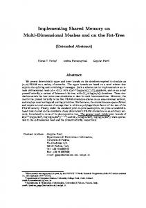
ABSTRACT The speed of optical transmission links is growing at a rate which is difficult for the micro-electronic technology of ATM switches to follow. In order to cover the transmission rate gap between optical transmission links and ATM switches, ATM switches operating at multi Gbit/s rate have to be developed. A 10 Gbit/s/port shared memory ATM switch is under development at Linköping Institute of Technology (LiTH) and Lund Institute of Technology (LTH) in Sweden. It has 8 inputs and 8 outputs. The switch will be implemented on a single chip in 0.8 µm BiCMOS. In this paper, we report on a performance analysis of the switch under a specific traffic model. This traffic model emulates the LAN type of traffic. Performance analysis is crucial for evaluating and dimensioning the very high speed ATM switch. 1 INTRODUCTION The interest of building switches that operate with higher transmission rates than 155 Mbit/s/port and 622 Mbit/s/ port is increasing. Academic and Industrial research is concentrating on finding new ATM switch architectures operating at the speed of multiple Gbit/s/port (see work presented by Plaza (1995), Lazraq, Bergstedt, Mokhtari, and Tenhunen (1996), Watanabe, Nakasha, Kato, Odani and Abe (1993), Hino (1995)). Two switch architectures have been proposed within the Swedish ATM Platform project (SWAP), one suited for GaAs-MesFET technology and one for BiCMOS technology. Paper proposed by Lazraq, Bergstedt, Mokhtari, and Tenhunen (1996) gives a detailed description of the switch architecture mentioned first, which is suitable for
implementation in GaAs-MeSFET technology and targeted to operate at 10 Gbit/s per port. The switch proposed by Lazraq, Bergstedt, Mokhtari and Tenhunen (1996) supports the following features: (1) In one chip a 2x2 switching element could be implemented, (2) Symmetrically built, (3) Parallel routing information transfer, (4) Shift register-based internal buffers, and (5) It has a simple protocol between the buffers for the read operation. At Linköping Institute of Technology (LiTH) and Lund Institute of Technology (LTH) the secondly mentioned switch architecture, designed for BiCMOS technology, has been developed (see Andersson and Lind 1996). The LiTH/LTH switch contains more inputs/outputs (8x8 switch) in comparison with the 2x2 switch presented by Lazraq, Bergstedt, Mokhtari and Tenhunen (1996). A short presentation of the LiTH/LTH switch is given in this paper. We present the performance analysis of the proposed switch under a specific traffic model. This traffic model emulates a LAN type of traffic. A larger NxN switch where a number of LiTH/LTH switches connected together, has also been modelled and simulated. The simulation results are used for dimensioning the switch. 2 DESCRIPTION OF THE SWITCH The features of the switch are: •
• • •
1065
A 8 x 8 switch element with serial inputs and outputs operating at 10 Gbit/s/port. The switch could be implemented in one chip. Shared buffer architecture. The buffer memory holds 256 ATM cells.
1066
•
Lazraq, Brundin, Andersson, and Arvidsson
A possibility to use the switching element to build larger units: switch fabrics.
2.1 Operation Principle The basic principle used is to time demultiplex each incoming stream to fully parallel ATM format (424 bits), perform time switching on the cell streams using a shared output buffer architecture, and then time multiplex the outgoing cells back to bit serial format. Figure 1 shows a block diagram of the switch. 8 x 1 bit @ 10 Gbit/s
8 x 1 bit @ 10 Gbit/s 8 x Bitsync & 1-16 demux
Bipolar Si (CML I/O)
Main demux 8 x 16bit @ 622 Mbit/s to 1 x 424bit @ 188 Mbit/s
HEC/Cell align
VP/VC lookup
Si CMOS only
1 x 424 bit @ 188 Mcell/s
8 x 16 bit barrel shifters
Sha u erdffer b 256 cells by 424+8 bit @ 376 Mword/s (2.6 ns access)
8 x 16 -1 mux
Main mux 8 x 16bit @ 622 Mbit/s to 1 x 424bit @ 188 Mbit/s
Figure 1: Block Diagram The incoming links each carry a continuous stream of ATM cells. The streams are assumed to be synchronous with a common system clock but may have individual bit level positions and phase. Each incoming bit-stream is individually synchronized to a common clock and then time demultiplexed to a 16-bit wide data stream with a 622 MHz rate. The 16-bit streams are individually routed through a shift unit, capable of extracting any 16-bit window from two consecutive 16-bit words, to the main demultiplexer block. In principle, the main demux consists of eight identical columns each having a 16-bit bus in the middle and 2*424 dual ported SRAM cells along its edges. The write ports of the memory are connected to the 16-bit bus, and the read ports from each 16-cell row (a row runs across all eight columns, connecting to 2 SRAM cells in each column) are connected to a common sense amplifier at the demux’s right edge (referring to Figure 1). I.e., each column implements a double buffering scheme where one set of 424 memory cells are available for writing (16 bits at a time), and the other 424 cells can be independently and simultaneously read to obtain a 424-bit ATM cell from the corresponding input link. The demux block sequentially reads each column in a cyclic fashion to produce a continuous cell stream with 188 MHz rate (8 links * 622 MHz * 16/424 bits). Addressing of the proper SRAM cells for reading and writing is performed by cyclic token passing within the demux block, and does not require any external sequencing except during the initial synchronisation of the incoming bit streams.
Between the main demux and the buffer memory the cells pass two blocks, HEC/cell align and VP/VC lookup. The primary function for the first block is to verify the header checksum for the ATM cells. This is also required by the ATM standard to perform cell alignment, i.e. to find the cell boundaries within the continuous bit-streams on the input links. The cell alignment is normally performed only after a link failure. The procedure is to assume a certain cell boundary and check for correct HEC. New bit positions are tried, by controlling the barrel shifter and token passing in the main demux individually for each link, until a correct HEC is encountered. Once a few cells with correct HEC have been received, alignment is considered complete and the current bit position is fixed. From this point the block only checks for corrupted cell headers, and inserts idle cells as substitution for cells with corrupt header. The VP/VC block performs table lookup based on the VCI in the cell header. Cells arriving from the main demux are aligned so that the 424-bit bus carries the payload from one cell and the header of the subsequent cell (referring to a specific input link). This allows the HEC calculation and VCI lookup to be pipelined over eight 188 MHz cycles; 8 x 5.3 ns = 42.4 ns, which makes it possible to perform off-chip VP/VC lookup. The VP/VC block also associates internal routing information to the cells. The routing information is forwarded to the buffer memory controller where it indicates to which output queue the incoming cell should be appended. Basically, the buffer implements nine logical FIFO-queues, one for each output queue and a separate idle cell queue. Any memory position can be allocated to any queue and always belong to exactly one of the queues. Each clock cycle one ATM cell is removed from a queue (to be output), and one cell coming from the VP/ VC block is inserted. The output cells, read from the buffer memory at a rate of 188 MHz, are serialized in the main mux block, which is similar to the main demux except that read and write ports on the SRAM cells are swapped, allowing 424-bit wide writes and 16-bit wide reads. Each output link corresponds to a 16-bit wide 622 MHz rate dataflow from the columns of the main mux block. Finally, the 16-bit wide flows are time multiplexed into bit-serial format to be transmitted on the eight 10 Gb/s output links. Read and write operations in the shared memory are described in more detail in the following section. 2. Shared Memory The shared memory is organized as 256*(424+8) SRAMcells. This space is used for holding 9 queues, one for each outgoing channel and one containing free cells, which are filled with idle-cells. The beginning and the end of each queue are indicated by two pointers:
Modeling a 10 Gbit/s/port Shared Memory ATM Switch
“Start_of _queue” pointer and “End_of_queue” pointer. The elements in the queues are linked together by pointers: the 8 bits trailing the ATM cell is used as a pointer to the next cell in the queue. The memory is capable of performing two 432-bit accesses, one read and one write, during one cycle of the buffer controller. In effect, the memory is accessed using a 376 MHz clock. The algorithm of the buffer controller is very simple. First a read operation is done then a write operation. 2.2.1 Read Operation The queues for the outgoing channels are read in a roundrobin way. The cell is read at the address indicated by the “Start_of_queue” pointer. If the queue is empty, the queue containing idle cells is read. The address read is marked as free. After the read operation “Start_of_queue” pointer is updated with the address of the next link within the linked list. Refer to Figure 2 for a description of the shared memory reading algorithm. Read_In_Shared_Memory(queue); { if (Start_of_queue[queue] = End_of_queue[queue]) {
/* Check if the queue to read is empty */ /* If yes take the queue with idle cells */ read_queue = idle_queue;
} else read_queue = queue; /* read the cell from the given address */ pop(Start_of_queue[read_queue]); /* mark the read memory address as free */ Free = Start_of_queue[read_queue]; /* update Start_of_queue pointer to new address */ Start_of_queue[read_queue] = pointer[Free]; }
Figure 2: Pseudo Code for the Read Operation in the Shared Memory 2.2.2 Write Operation The cell will be written in the queue indicated by the routing information. The “End_of_queue” pointer of each queue gives the address where the cell will be written. The basic idea is that every queue has a reserved row of the memory for the next cell to be written, thus the effective queue space is reduced to 247 positions. After the write operation the “End_of_queue” pointer is updated to the address stamped as free (see Read Operation above). The algorithm for writing in the shared memory is described in Figure 3.
1067
Write_In_Shared_Memory(queue); { /* write the cell in the given address */ append(End_of_queue[queue]); /* update pointer */ pointer[End_of_queue[queue]] = Free; /* update end_of_queue pointer to new address */ End_of_queue[queue] = Free; }
Figure 3: Pseudo Code for the Write Operation in the Shared Memory 3 TRAFFIC MODEL The traffic offered at each input of the switch is a superposition of independent arrival streams. It was assumed that the arrivals in each stream can be modelled by a Switched Poisson Process (SPP), i.e., a Poisson process in which the average rate randomly alters between two values according to transitions in an independent twostate Markov chain. An SPP is a special case of a Markov Modulated Poisson Process (MMPP), see e.g. Fisher (1992). An SPP has four parameters, the two arrival rates lambda1 and lambda2 and the two state transition rates r12 and r21 of the modulating chain. The values of these determine the characteristics of the generated traffic. Depending on which traffic characteristics one wants to match, e.g., moments and correlations, the parameters can be set in a number of ways. We chose the method proposed by Gusella (1991), for an overview and discussion of methods see, e.g, Gusella method proposed by Arvidsson (1996). The traffic actually fitted to was selected with the aim of being equivalent to LAN-traffic, as LAN emulations and LAN interconnections are seen as major applications in early ATM networks. To obtain ATM traffic with LAN characteristics we took a segment from the Ethernet measurements carried out at Bellcore (see Measurements 1989) and converted the traffic to ATM according to the following scenario: The LAN is a 10 Mbit/s Ethernet, and it is connected transparently to the ATM network via a 34 Mbit/s link. Before the LAN packets are delivered over this link to the network, the Ethernet overhead is stripped off, and the remaining data packed into cells. Each 53 octet cell can take 44 octets of Ethernet data, since 4 octets “payload” are used for AAL3/4 overhead, and the last 5 octets constitute the ATM header. The Bellcore measurements actually cover several years. In order to get tractable traces, we selected 10 subtraces of 2.00 seconds each with 42% and 85% of the actual peak value observed in intervals of this lengths in the entire material made available to us. Each subtrace
1068
Lazraq, Brundin, Andersson, and Arvidsson
results in a unique set of matching SPP-parameters. Some aspects on the accuracy of the resulting models are given in the work presented by Arvidsson (1996). To load each input of the switch to a fraction F of its nominal bandwidth R = 10 Gbit/s, N MMPPs must be superposed. N is given by the following relation. F⋅R N = ------------ , A⋅B
(1)
where A is the link data rate (34 Mbit/s), B is the average relative rate of the model sources, i.e., of the subtraces fitted to. B is immediately obtained from the fitted parameters as ( lambda1 ⋅ r21 + lambda2 ⋅ r12 ) B = ------------------------------------------------------------------------------------ . r12 + r21
(2)
The obtained value of N must then be rounded to the nearest integer. 4 TECHNOLOGY The switch is aimed to be implemented on a single chip in 0.8 µm BiCMOS. Except for the high-speed I/O, refer to Figure 1, the design is pure CMOS based on true single phase clocking (TSPC) (see work presented by Yan and Svensson 1989). Two aspects with regard to the choice of BiCMOS technology have been the major issues: (i) The use of a moderate clock speed, and (ii) The use of a high degree of parallelism. The bipolar I/O is designed in high-speed CML circuit technology, with transistor fT of 12 GHz. The estimated power consumption is 30 W, of which the bipolar parts, including I/O, account for 10 W. Experience on some critical building blocks has been gained: e.g., 5 Gbit/s MUX/DEMUX in 1.2 µm BiCMOS, a single column of the main demux fabricated and verified up to 575 MHz, a 275 MHz 256 x 256 buffer memory, and a prototype implementation of logic corresponding to one of the output queue controllers has been fabricated and verified up to 300 MHz (188 MHz required). 5 SIMULATION A model of the 10 Gbit/s/port shared memory ATM switch structure has been developed (Brundin 1996), and verified by simulation. The main objective with the simulations were to obtain information regarding 1) cell delay, 2) cell loss and 3) shared memory queue usage. For this purpose a cell level model was appropriate, avoiding implementation- and technology specific details. Instead of using actual ATM cells for the simulation, records with the following fields were used: 1) cell arrival time, 2) cell departure time, 3) target port, 4) source (input port) and 5) cell sequence number.
The switch was modelled in blocks, as described in Figure 1. The input 1-16 demultiplexers, barrel shifter array and the output 16-1 multiplexers were not functionally modelled since they represent only constant delays and do not interfere with the internal processing sequence in the switch. These blocks represent a total cell delay of approximately 1/9 cell time (42.4 ns), about 5 ns. Of the modelled blocks, all but the shared memory buffer can be modelled with the average delay for a cell payload passing through these blocks. The shared memory buffer is modelled with the controller algorithm described above, handling the nine queues accordingly. It was appropriate to introduce stepped time for the model, and the most suitable time quantity was 1/(188 MHz), the cycle time for the fully paralleled ATM cells. Using the cell level approach, this cycle time (5.3 ns) can be used as the smallest time step in modelling all of the switch blocks. The HEC and routing lookup blocks can be modelled as delays of 2 cycles when the header processing is disregarded and the effective cell transport through the switch is considered. It takes 8 cycles (1 cell time) for a cell to be written into the main S/P, and the average cell is buffered for 4 cycles. Thus the effective delay through the S/P is 12 cycles (1.5 cell time). The main P/S is modelled with a delay of 1 cycle, as cells immediately start to be output when they have been written to it. The S/P and P/S work synchronously in the sense that they process the same column at the same cycle. Thus when the S/P delivers one cell to the HEC block, from input channel N (N=1...8), the P/S receives a cell from the buffer memory going to output channel N. In the buffer memory, the eight output queues are read sequentially in a round robin manner. This gives that, on average, an incoming cell has to wait 4 cycles in a previously empty queue before it is output. With higher loads (up to 100%) switch delays are much dependent of output queue sizes. We have used the C language to develop the stepped simulator. At every time step certain operations on the cells are simultaneously performed in the switch. The C language simulator executes these operations sequentially for each time step, upholding the operation principle, with a minimum of simulation setup overhead. Some larger NxN switches (N>8), where a number of these switches are interconnected have also been modelled and simulated. These larger switches have been implemented as two-stage fabrics. Every cell time all sources transmit cells. ATM cells or idle ATM cells are transmitted by the sources according to the traffic applied (superposed MMPP traffic in our case as described below). A random destination scheme is employed for the non-idle ATM cells. During the cell time, N cells (where N is equal to the number of input in the switch) are input in the switch, read from the shared
Modeling a 10 Gbit/s/port Shared Memory ATM Switch
6 PERFORMANCE EVALUATION
Fraction idlecells in buffer memory (%)
The performance evaluation is focused mainly on cell loss and average delay times in the switch. Several switch sizes have been modelled, all being of type N x N with N = 8, 16, 32, and 64. For the various switch sizes, we generated 50 106 cells/input. The cell loss and delay times investigations have been done with two types of traffics (MMPP and Bernoulli traffic) modelling the arrival process at each input link. The two traffic types were applied in two average loads (80% and 90%). The only criterion to get cell loss in the switch architecture is to have no idle cells in the idle cell queue. Figure 4 shows the fraction idle cells in buffer memory versus the switch sizes. When the average load of 80% is applied on different switch sizes, the amount of idle cells in the shared memory varies between 93% to 95%. For higher load (90%) the amount of idle cells may vary in the memory depending on the switch size and the traffic type. For the switches larger than 8 x 8, two stages of switch elements were needed, and the figures in the diagram represents the mean value of the averages from the first and second stage of the respective switches. The first stage of the two stage switches always exhibited the lower fraction idle cells in the buffer memory. The amount of idle cells in the memory was never under a 85% average in any stage of the simulated switches. This means that the probability to get cell loss in the switches is very small. On 3.2 10 9 cells injected in a 64 x 64 switch, no cell loss has been identified with any of the traffic types or loads.
95
Bernoulli 80%
The average cell latency versus the switch size is shown in Figure 5. The latency increases rapidly (approximately twice of the value) when passing from one-stage fabric to a two stage fabric. This is due to the fact that every cell has to pass two ATM switching elements before being output. The largest average latency observed is 466 ns, approximately 11 cells times. 500 Average cell switch delay (ns)
memory, written in the shared memory, and output from the switch.
1069
MMPP 90% Bernoulli 90%
400
MMPP 80%
300 Bernoulli 80%
200
100
8x8 16x16 32x32 Switch size (# inputs)
64x64
Figure 5: Average Delay 7 CONCLUSION We simulated a 10 Gbit/s/port shared memory ATM switch under a specific traffic model in order to get the performance analysis for evaluating and dimensioning the very high speed ATM switch. The performance evaluation has been focused mainly on cell loss and delay times in the switch. The result of our study shows that the switch has a very low cell loss probability. We have demonstrated that LiTH/LTH switch architecture is well dimensioned for the studied traffics (Bernoulli and MMPP with average loads of 80% and 90%). The future work within the project is to continue simulations with other traffic models, networks and to fabricate the switch.
MMPP 80%
REFERENCES 90 Bernoulli 90% MMPP 90%
85
8x8 16x16 32x32 Switch size (# inputs)
64x64
Figure 4: Buffer Memory Occupancy
Andersson, P., and C. Svensson. 1996. A VLSI architecture for an 80 Gb/s ATM switch core, Proceedings of IEEE International Conference on Innovative Systems in Silicon, 9-15. Arvidsson, Å., and C. Lind. 1996. Using Markovian models to replicate real ATM traffics, in (Kouvatsos ed.) Performance Modelling and Evaluation of ATM Networks, vol. 2: 39-54. London: Chapman and Hall. Brundin, J. 1996. Performance analysis of a high-speed 10 Gbit/s/port ATM switch. Master’s thesis, Electronic System Design Laboratory, Royal Institute of Technology, Stockholm, Sweden.
1070
Lazraq, Brundin, Andersson, and Arvidsson
Fischer, W. 1992. The Markov modulated Poisson process (MMPP) cookbook, Performance Evaluation 18: 149-171. Gusella, R. 1991. Characterising the variability of arrival processes with indexes of dispersion, IEEE Journal on Selected Areas in Communications 9 (2):203-211. Hansen, F. 1993. 2.5 Gbit/s ATM switch element, DTH, internal note, Electromagnetics Institute, Denmark. Hino, S. 1995. Asynchronous transfer mode switching LSI chips with 10 Gb/s serial I/O ports, IEEE journal of Solid-State Circuits 30 (4): 348-352. Lazraq, T., P.O. Bergstedt, M. Mokhtari and H. Tenhunen. 1996. ATM-switching element design for 10 Gbit/s/port data rate, IEEE International Communication Conference 96, 669-675, Dallas, USA. Measurements made on August 29, 1989 at 11:25 a.m. at Bellcore Research and Engineering Centre, Morristown, New Jersey, USA. Plaza P. 1995. 2.5 Gbit/s ATM switch chip set, IEEE ASIC Conference and Exhibit, 173-176. Austin, USA. Watanabe, Y., Y. Nakasha, Y. Kato, K. Odani, and M. Abe. 1993. A 9.6-Gb/s HEMT ATM switch LSI with event-controlled FIFO, IEEE Journal of Solid-State Circuits 28 (9): 935-940. Yuan, J., and C. Svensson. 1989. High speed CMOS circuit technique, IEEE Journal of Solid-State Circuits 24: 62-71. AUTHOR BIOGRAPHIES TAWFIK LAZRAQ received the M.Sc. degree in electrical engineering from Ecole Polythechnique Federale de Lausanne, Switzerland, in 1987. He received the Techn. Lic. degree in 1993, and the degree Doctor of Technology in 1995 from the Royal Institute of Technology (KTH), Stockholm, Sweden. From 1987 to 1989 he worked at Brown Boveri in Baden, and Ericsson Telecom in Stockholm on electronics. From 1989 to 1993 he
worked at the department for Applied Electronics on road traffic information and communication networks. In 1993 he joined the Electronic System Design Laboratory at KTH. His research interest is mainly in high-performance ATM switching. He spent nearly one year at CERN, where he carried out research on evaluating ATM for event-building. JAKOB BRUNDIN received the M.Sc. degree in electrical engineering at the Royal Institute of Technology (KTH), Stockholm, Sweden, in 1996. His research interest mainly concerns high-performance integrated hardware development. After participating in a pan-european project at the Electronic System Design Laboratory at KTH with the purpose of studying Best Practice in industrial electronic system design, he is presently with the Microelectronics division at Ericsson Radio Systems in Stockholm. At Ericsson his work includes advanced ASIC and DSP-core design. PER ANDERSSON was born in Malmö, Sweden, in 1960. He received his M.Sc. degree in 1986, and his Ph.D. degree in 1991, both from the Lund University. Currently he is an Associate Professor at the Department of Information Technology at the Lund University. His research interests are methods, tools and principles for the design of efficient microelectronics systems. Dr. Andersson is a member of the IEEE. ÅKE ARVIDSSON received his Ph.D. in 1990 from the Lund Institute of Technology in Lund, Sweden, where he held a position as associate professor until 1994. He has held positions as visiting professor at the Bond University, Qld., Australia, and at the University of Adelaide, S.A., Australia, and is currently acting professor of teletraffic systems at the University of Karlskrona/Ronneby in Karlskrona, Sweden. His main research interests include performance evaluation and optimization of traffic management and control in telecommunication systems, in particular ATM-, IP-, and signalling networks.