FULL PAPER Conductive Nanocomposites
www.advmatinterfaces.de
Positive Temperature Coefficient (PTC) Evolution of Segregated Structural Conductive Polypropylene Nanocomposites with Visually Traceable Carbon Black Conductive Network Shuaiguo Zhao, Guojie Li, Hu Liu, Kun Dai,* Guoqiang Zheng, Xingru Yan, Chuntai Liu, Jingbo Chen, Changyu Shen, and Zhanhu Guo* many CPCs exhibit intriguing positive temperature coefficient (PTC) effect,[17–20] which refers to a sharp increase in volume resistivity near the melting point (Tm) of the polymer matrix. Recently, the polymer-based PTC materials have demonstrated potential engineering promise such as overcurrent protection materials, self-regulating heaters, and microswitch sensors.[17,18,21] To date, the origin of the PTC effect in different systems has been studied. For instance, Kono et al.[19] reported that the observed PTC effect in the 20 vol% Ni/ polyvinylidene fluoride (PVDF) CPC at far below the Tm of PVDF arose from a slight increase in the specific volume and the gap between Ni particles. Sumita and coworkers.[22,23] and Deng et al.[24] attributed the resistivity relaxation behaviors of CPCs during annealing treatment to the agglomeration of diffused fillers and the stretched polymer chains. Zha et al.[25] found that a more stable 3D hybrid conductive network of carbon black (CB)/carbon nanotubes (CNTs) improved the PTC effect repeatability of PVDF/ultrahigh molecular weight polyethylene (UHMWPE) CPC. However, the mechanism of the volume resistivity-temperature (ρ-T) behavior has not been established in the CPC systems. One main challenge is to visually trace the movement of conductive fillers, especially for the CPCs with random filler distribution. Recently, the CPCs with a selective distribution of conductive filler have been studied with the movement of conductive fillers being monitored[26,27] and some interesting findings on temperature dependent resistivity behavior have been discussed. For example, negative temperature coefficient (NTC) effect, defined as a decrease in the resistivity after being at the Tm of polymer matrix, is usually theoretically attributed to the formation of flocculated structure through the reaggregation of conductive fillers.[28,29] However, Fengand Chan.[26] demonstrated that the NTC effect in the ethylene tetrafluoroethylene (ETFE) composites with high density polyethylene (HDPE) wrapped CB was not ascribed to the formation of the agglomerated structures arising from the too large conductive CB/HDPE phase in the ETFE matrix. Pang et al.[27] found that isothermal treatment (IT) was an effective strategy to tune the PTC effect of graphene nanosheets
Electrically conductive carbon black (CB)/polypropylene (PP) nanocomposites with a segregated structure are fabricated by localizing CB particles at the interfaces among the PP granules. Interesting double-peak positive temperature coefficient (PTC) effect when exposed to temperature field is observed and ascribed to the breakage of unique segregated conductive network due to the volume expansion stemming from the crystal melting of interfacial PP and the bulk PP matrix. With extending thermal treatment time, the PTC intensity first increases and then decreases obviously. Long treatment time is required for the composites with high CB loadings to reach the PTC intensity maximum value. This phenomenon is attributed to the evolution of segregated microstructure during the thermal treatment, which is traced visually in situ through an optical microscope (OM). The diffusion due to the concentration gradient and the subsequent aggregation of CB particles lead to this behavior. A model based on the OM observation is proposed to reveal the origin of this novel resistivity-temperature behavior.
1. Introduction Electrically conductive polymer composites (CPCs) have attracted enormous interests from both industry and academia due to their wide applications, such as thermistors, electromagnetic interference shielding, and sensors.[1–16] Among them, S. Zhao. G. Li, Dr. H. Liu, Prof. K. Dai, Prof. G. Zheng, Prof. C. Liu, Prof. J. Chen, Prof. C. Shen College of Materials Science and Engineering The Key Laboratory of Advanced Materials Processing & Mold of Ministry of Education Zhengzhou University Zhengzhou 450001, P. R. China E-mail:
[email protected] Dr. H. Liu, Dr. X. Yan, Prof. Z. Guo Integrated Composites Laboratory (ICL) Department of Chemical & Biomolecular Engineering University of Tennessee Knoxville, TN 379996, USA E-mail:
[email protected];
[email protected] Prof. K. Dai State Key Laboratory of Polymer Materials Engineering Sichuan University Chengdu, Sichuan 610065, P. R. China
DOI: 10.1002/admi.201700265
Adv. Mater. Interfaces 2017, 1700265
1700265 (1 of 10)
© 2017 WILEY-VCH Verlag GmbH & Co. KGaA, Weinheim
www.advancedsciencenews.com
www.advmatinterfaces.de
(GNS)/UHMWPE composites. The diffusion of GNS seemingly contradicted the common theory, that is, the fillers would coagulate each other to reduce the total interfacial energy and reached a thermodynamic equilibrium during IT.[30,31] However, systematically in situ visualization on the evolution of conductive network morphology remains largely unexplored. To achieve this target, two key influential factors should be optimized. The first is melt viscosity of polymer matrix. Polymer with a relatively low melt viscosity would be a favorable alternative since polymer with a high melt viscosity, such as UHMWPE (melt flow index, MFI = 0 g/10 min, 230 °C, 2.16 kg), is detrimental for the movement of conductive fillers. The second is the filler size. The smaller the size of the conductive filler, the stronger the mobility of conductive fillers in the composite melts. However, any prior studies did not involve these two factors. In this paper, low-dimension CB (0D) was selected as conductive filers and polypropylene (PP) with a relatively low melt viscosity (MFI = 3 g/10 min, 230 °C, 2.16 kg, Section 1 in the Supporting information) was used as the polymer matrix. The CB was selectively arranged at the interface among the PP pellets, forming a segregated conductive network. The PTC behavior of the
CB/PP (3.31 vol%) was first studied, then four consecutive heating/ cooling runs were conducted to investigate the variation of the PTC intensity (PTC intensity is defined as IPTC = log( ρ max /ρRT ) , where ρmax is the maximum resistivity in the heating process, ρRT is the original resistivity at room temperature). To reveal the mechanism of the PTC effect, the ρ-T behavior was investigated further after prolonged thermal treatment at 200 °C. The microstructural evolution of CB/PP during the thermal treatment was examined in situ by OM with a heating stage. The effect of the CB concentration was studied for comprehensive analysis. Based on the experimental results and the microstructural evolution, a competition process between the diffusion and the aggregation of conductive fillers was confirmed, which could provide a further insight into the mechanism of ρ-T behaviors.
2. Results and Discussion 2.1. Morphologies Figure 1a shows the morphology of original PP particles. The PP particles are observed to exhibit spherical shape with
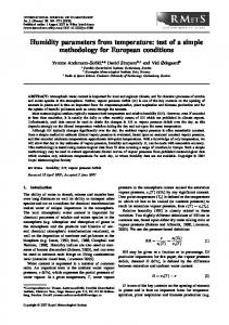
Figure 1. FESEM images of a,b) PP particles, c,d) CB coated PP particles, b,d) are the surfaces of (a) and (c) at a higher magnification, respectively, e) fractured surface of 3.31 vol% CB/PP film, f) the interface region between CB-coated PP particles, g) optical image of 3.31 vol% CB/PP, h) TEM images of CB conductive layer between PP regions and i) interface region between CB and PP with a higher magnification for 3.31 vol% CB/PP.
Adv. Mater. Interfaces 2017, 1700265
1700265 (2 of 10)
© 2017 WILEY-VCH Verlag GmbH & Co. KGaA, Weinheim
www.advancedsciencenews.com
www.advmatinterfaces.de
2.2. Thermal Properties The volume expansion of polymer, stemming from the melting of crystalline region and the thermal expansion, is the key influencing factor for the PTC effect of semicrystalline polymerbased composites.[19,42–44] Therefore, the discussion on the thermal properties regarding the melting point (Tm) and crystallinity is necessary. Figure 2 shows the differential scanning calorimetry (DSC) curves of the pure PP and CB/PP composites containing 3.31, 3.79, and 4.26 vol% CB, respectively. Apparently, the Tm and the shapes of these scans appear to be almost the same. Detailed information of these DSC curves is listed in Table 1. In Table 1, the crystallinity first increases and then decreases with increasing the CB content. Similar phenomenon has been reported for single wall carbon nanotubes (SWNTs)/ HDPE,[45] SWNTs/PP,[46] CNTs/PP, and copper nanowires (CuNWs)/PP,[47] etc. This phenomenon can be explained as follows. The PP crystallization is controlled by both crystal nucleation and crystal growth. With increasing the CB content, the nucleating sites increase (Figure S4, Supporting Information), resulting in the increase in crystallinity; however, the formation
Adv. Mater. Interfaces 2017, 1700265
163.2 °C
Endo.
163.4 °C
Heat flow (a.u.)
a diameter of 5–55 µm and mean size of 29 µm (Figure S3, Supporting Information). The surface (Figure 1b) of the PP particle is very rough, which is beneficial for the adsorption for CB particles. After the evaporation of ethanol, the PP particles surfaces are uniformly coated with CB aggregates (Figure 1c,d). Figure 1e shows the fractured surface of the CB/PP CPCs. Obvious interfacial regions are observed (Figure 1e,f), indicating a segregated conductive network structure. This morphology is also observed by OM and transmission electron microscopy (TEM) (see Figure 1g–i), where CB rich region was segregated by PP regions. The CB rich region is dark in OM and TEM images, while the PP appears dark in field emission scanning electron microscope (FESEM) images. The construction of segregated conductive network can be understood from the fabrication process. During the hot compression, CB aggregates are relatively difficult to migrate into the PP matrix, forming a microstructure with a segregated conductive network.[32] This fabrication method is different from the solvent mixing method, which disperses conductive fillers in PP uniformly by using xylene as the solvent,[33–35] leading to much lower percolation threshold and higher conductivity than the reported CB/PP CPCs.[35] Specially, Figure 1g shows a diffuse interface, that is, the CB rich region is relatively broad. This broad region is evidently larger than the “nanowire-like” one of typical segregated CPCs,[23,36–40] for which, the interface is clear and the interface region is relatively narrow due to the poor mobility of conductive fillers. The comparison of Figure 1g and previous reports[23,29,32,41] indicates that the penetration of CB aggregates into PP matrix should mainly account for this unique segregated conductive network. The normal or shear forces caused convection in hot compression also has effect on this board interfaces morphology. This segregated conductive path could be considered as two different components, i.e., the dense conductive channels just at the interface; and the thin conductive paths adjacent to the interfacial region.
163.2 °C 163.6 °C
3.31 vol% 3.79 vol% 4.26 vol% pure PP 80
100
120
140
160
180
Temperature (°C) Figure 2. DSC curves of the pure PP and CB filled PP composites with various CB contents at a heating rate of 2 °C min−1.
of an excellent CB conductive network can increase the difficulty to transport polymer chains due to the extremely high CB content at the interface region and the interaction between CB and polymer chains (Figures S5 and S6, Supporting Information).[45,48] Consequently, the growth of the formed crystal is restricted, leading to the overall reduction in crystallinity. Nevertheless, the difference between the crystallinity of these three composites was very small. A similar result is also reported by Hindermann-Bischoff and Ehrburger-Dolle in the CB/polyethylene (PE) composites.[49]
2.3. Temperature Dependence of Resistivity for Low CB Concentration Filled PP Figure 3 shows the ρ-T relationship of 3.31 vol% CB/PP composites for the consecutive four runs (for each run, the sample was heated to 200 °C at 2 °C min−1, held at this temperature for 5 min if without particular illustration and then cooled down at 2 °C min−1). Apparent PTC/NTC effects can be observed. In Figure 3a, as the temperature increases, the volume resistivity slightly increases and a sharp jump in resistivity is observed at around 151.7 °C, displaying a PTC resistivity peak. When the temperature is higher than 160.3 °C, interestingly, another PTC peak is observed obviously, i.e., this CB/PP with a single polymer matrix exhibits an interesting double PTC effect (Figures S6–S8, Supporting Information). This phenomenon Table 1. Detailed information of DSC traces of CB/PP containing different CB content. [Xc is the crystallinity; ∆H fobs is enthalpy of fusion, Tm is melting temperature; melting enthalpy for 100% crystalline iPP is 207 J g−1.[41] ∆H fobs [J g−1]
Tm [°C]
Xc [%]
118.6
163.2
61.6
3.79
115.9
163.4
60.8
4.26
110.2
163.2
58.5
CB content [vol%] 3.31
1700265 (3 of 10)
© 2017 WILEY-VCH Verlag GmbH & Co. KGaA, Weinheim
www.advancedsciencenews.com
www.advmatinterfaces.de
(a)
Volume Resistivity(Ω.cm)
Volume Resistivity(Ω.cm)
8
10
Run 1
7
10
6
10
5
10
4
10
3
10
11
10 10 10 9 10 8 10 7 10 6 10 5 10 4 10 3 10
20 40 60 80 100 120 140 160 180 200
(b)
Run 2 Run 3 Run 4
Run 4 Run 3 Run 2
Heating
20 40 60 80 100120140160180200220
Temperature (°C)
Temperature (°C)
Figure 3. ρ-T relationship of 3.31 vol% CB/PP composite during heating process a) for the first run and b) for the other three runs. The dotted line illustrates the ρ−T behaviors beyond the measurement range of the instrument.
is markedly different from other results with only a resistivity peak of CPC containing single polymer matrix (Figure S9, Supporting Information).[17,28,50–52] The comparison of thermal properties in Figure 2 and PTC effect in Figure 3a suggests that the first peak at around 151.7 °C is ascribed to the CB structures rather than the melting of different forms of PP crystals. As mentioned above, for the segregated CB/PP with a relatively low melt viscosity (Section 1 and Figures S10 and S11, Supporting Information), the morphology is different from the typical segregated CPCs with a high melt viscosity matrix, such as CB/UHMWPE,[53] CNTs/UHMWPE,[54,55] and graphene/ UHMWPE,[27] etc. The interface is not clear, on the contrary, it is vague due to the CB migration during the hot compression, causing a weak conductive network near the interfacial regions (see Figure 1g). With increasing the temperature, these feeble conductive paths adjacent to the interfacial region were damaged by the increased specific volume from the small amount of melting of interfacial PP, causing the first PTC effect. This phenomenon is a novel nature of this segregated CPCs based on the relatively low melt viscosity matrix and it has not been reported in the open literature. As for the second PTC peak (160.2 °C), it is widely accepted that the rapid volume expansion stemming from a large amount of melting of the bulk PP crystalline region pushes the CB particles apart, leading to an increase in resistivity. This novel double-peak PTC (DP-PTC) creates an unchanged resistivity level within a range of more than 10 °C and enlarges the switch temperature range of the PTC materials. Moreover, the second PTC peak temperature appears at ≈160.2 °C, instead of the Tm of 163.2 °C. This slight shift might be related to the low CB content.[17,19,51,56] The subsequent NTC effect is due to the rearrangement and reformation of conductive network in the molten polymer. Figure 3b shows the ρ-T behaviors in the following three runs. Obviously, the maximum resistivity increases significantly with increasing the run number. Here, the IPTC is employed to evaluate the ρ-T behaviors. Specifically, considering the migration of CB particles from the interface region to PP matrix, IPTC of the composite is defined as the IPTC of the second PTC peak, which can better reveal the motion of CB particles. The IPTC values at corresponding runs are listed in Table 2. The IPTC increases obviously with increasing the run number. However, in literature, the IPTC always presents an evidently descend for Adv. Mater. Interfaces 2017, 1700265
the CB/EVA,[57] CB/PP,[52] carbon nanofiber/unsaturated polyester resin nanocomposites,[58] multiwalled carbon nanotubes (MWNTs)/UHMWPE/branched low molecular weight polyethylene (LMWPE),[21] and CB/HDPE,[59,60] etc. In our case, when the temperature was above the Tm, it is deduced that some CB particles would migrate from the interfacial region into the PP matrix due to the CB concentration gradient. As the run number increased, the interfacial conductive network was deteriorated gradually. Consequently, the improvement in IPTC was observed. In order to further investigate the underlying mechanism of the increasing PTC effect, an enhanced thermal treatment is carried out. As mentioned above, the isothermal treatment at a temperature above the Tm of polymer matrix is proven to be an effective approach to explore the origin of the ρ-T behaviors. In this paper, a strong isothermal treatment at 200 °C for different periods was then applied; the variation of IPTC before and after the treatments was tested respectively for comparison. Figure 4 displays the ρ-T relationship of 3.31 vol% CB/PP segregated CPCs during heating process for six runs after experiencing different ITs. Surprisingly, the IPTC first increases and then decreases after the ITs. A switch in IPTC appears after the CB/PP sample undergoes 120 min IT, suggesting that the equilibrium time of the 3.31 vol% CB/PP segregated CPC is ≈120 min. This fascinating phenomenon agrees well with the competition of the migration of CB and the subsequent CB aggregation in a high temperature field, the latter process has been reported by a mass of literature on ρ-T behaviors.[22–24] At the equilibrium state, the migration of CB particles is comparable to the reaggregation of the CB particles, exhibiting a IPTC peak. After that, the aggregation of the CB particles dominates the competition, resulting in the decreasing IPTC. On the other hand, the DP-PTC faded away gradually after the first run both in Figures 3 and 4. After a short-term IT (several runs), some additional CB aggregates migrated from the interface into the PP adjacent to the interfacial region and enhanced Table 2. The IPTC in different runs. Run number IPTC
1700265 (4 of 10)
1
2
3
4
4.5
5.8
>5.9
>6.3
© 2017 WILEY-VCH Verlag GmbH & Co. KGaA, Weinheim
www.advancedsciencenews.com
10
10
8
10
region, which is in accordance with rapid increase of the second PTC intensity, therefore leading to less resistivity decay between the two peaks. A resistivity equilibrium can be reached gradually when the conductive network breakdown (owing to the polymer volume expansion) is counteracted by the conductive network formation (due to the migration or reaggregation of CB), leading to the disappearance of the DP-PTC.
8
10 PTC intensity
7
10
6
10
5
10
240 min
0
50 100 150 200 250 300
Run number
6
300 min 180 min 120 min 60 min 30 min before IT
4
10
2
10
20 40 60 80 100 120 140 160 180 200 220 240
Temperature (°C) Figure 4. ρ-T relationship of 3.31 vol% CB/PP composites during heating process for the six runs after different IT time. The insert illustrates the variation in IPTC after different IT time at 200 °C. The dotted line and the shaded region for resistivity and IPTC indicate that the change of the volume resistivity exceeds the upper measurement limit.
the intermixing degree between CB and PP. This decreased CB concentration gradient not only reduces the CB migration which is related to conductive network formation and but also reduces the robustness of conductive network in interfacial
(a)
6
10
8
PTC intensity
Volume Resistivity(Ω.cm)
9
10 10
7
10
6
10
5
10
4
10
1
5
10
2
3
4
5
Run number
Run 5 Run 4 Run 3 Run 2 Run 1
4
10
3
10
2
10
0
30
60
90
2.4. Temperature Dependence of Resistivity for Intermediate and High CB Concentration Filled PP In order to check the competition mechanism between the diffusion and the aggregation and to reveal the origin of the evolution of this novel PTC effects, the variations of PTC effects of the CB/PP with higher CB concentrations of 3.79 and 4.26 vol%, which would affect the mobility of the CB particles, were then examined. Figure 5 is the ρ-T relationships of the segregated CB/PP CPCs during heating process with an intermediate content (3.79 vol%) and a high concentration (4.26 vol%), respectively. Similarly, the increased IPTC in Figure 5a,c is observed obviously with increasing the run number. Moreover, both the IPTC first increases and then decreases when ITs are applied gradually, Figure 5b,d, being in good accordance with the results in Figure 4. Similar trend verifies the presence of the novel IPTC evolution in the segregated CB/PP again. 9
10
120 150 180 210
8
10
7
10
6
10
(b)
6
10
PTC intensity
10
Volume Resistivity(Ω.cm)
Volume Resistivity(Ω.cm)
12
10
www.advmatinterfaces.de
5
10
4
10
240 min
3
10
5
0
10
200 400 600 800
Time (min)
4
10
3
10
900 min 600 min 360 min 240 min 120 min before IT
2
10
-30 0
30 60 90 120 150 180 210 240
Temperature (°C)
Temperature (°C) 8
6
10
5
10
4
10
3
10
2
4
10
3
10
2
10
0
1
30
2
3
4
Run number
60
90
5
Run 5 Run 4 Run 3 Run 2 Run 1
120 150 180 210
7
10
6
10
5
(d)
10
PTC intensity
10
PTC intensity
Volume Resistivity(Ω.cm)
10
7
10
Volume Resistivity(Ω.cm)
(c)
5
10
5
10
4
10
3
10
600 min
2
10
0
500 1000 1500 2000
Time (min)
4
10
2100 min 1680 min 900 min 600 min 300 min
3
10
before IT
2
10
-30 0
30 60 90 120 150 180 210 240
Temperature (°C)
Temperature (°C)
Figure 5. ρ-T relationship during heating process: a) five consecutive runs for 3.79 vol% CB/PP, b) six runs after different IT time for 3.79 vol% CB/ PP, c) five consecutive runs for 4.26 vol% CB/PP, and d) six runs after different IT time for 4.26 vol% CB/PP. The insets in (a) and (c) illustrate the variation in IPTC with the increasing run number. The inserts in (b) and (d) illustrate the variation in IPTC after different IT time at 200 °C.
Adv. Mater. Interfaces 2017, 1700265
1700265 (5 of 10)
© 2017 WILEY-VCH Verlag GmbH & Co. KGaA, Weinheim
www.advancedsciencenews.com
www.advmatinterfaces.de
total interfacial energy and reach an equilibrium, particles or aggregates always tend to aggregate when CPC is annealed at a temperature above Tm of the polymer matrix.[22,23,61] To check whether the experiment is dominated by this non-in-equilibrium mechanism, the temperature–resistance curves, namely, resistance relaxation behavior, was first evaluated. Figure 6 displays resistivity relaxation behavior during 300 min IT for CB/PP with varying CB contents. This can be described using a relaxation equation[62]
ρt /ρ0 = ρ ∞ /ρ0 + (1 − ρ ∞ /ρ0 ) exp ( −t /τ ) (1) where ρ∞ is the resistivity of the composites after a long-term IT, ρ0 is initial resistivity of the composites at the beginning of IT, ρt is resistivity at time t, and τ is the relaxation time, which represents the reconstruction speed of the CB conductive networks. Through fitting the experimental results, ρ∞/ρ0 and τ for CB/PP with various CB content were obtained and shown in Table 3 by fitting the data points with Equation (1). The least square method was employed during the fitting. According to the fitting data in Figure 6, as CB content is higher, the fitting curves demonstrate a larger ρ∞/ρ0 and a shorter τ, indicating a smaller degree damage of the conductive network and a stronger reconstruction capability. The main reason is that a high CB concentration means a small inter-particle distance at the interface and therefore, a large chance of CB particles to aggregate. It seems that a rapid attenuation in IPTC should be expected with a strong reconstruction capability, which however is contrary to our experimental results. This suggests that the resistivity relaxation behavior is not the main reason for the novel evolution of the PTC effect during IT. As discussed above, the CB diffusion and the subsequent aggregation lead to this interesting phenomenon. The CB motion profile should thus be traced and studied in detail. In this paper, the design of the novel segregated structure provides an effective method to trace the morphology evolution visually. The
1.1
0.9 0.8 0.7 0.6 0.5 0.4 0.3
2.5. OM Observations and Mechanism Analysis The formation of conductive network is a thermodynamically non-in-equilibrium process.[22,23,58] In order to reduce the
Adv. Mater. Interfaces 2017, 1700265
3.31 vol% 3.79 vol% 4.26 vol% Fit line
1.0
ρt /ρ0
While two obvious differences are still observed, the first is about the DP-PTC phenomenon. For the CB/PP with a high CB content 4.26 vol% (Figure 5c,d), the DP-PTC cannot be detected in the first run, which is thought to be resulted from the high CB concentration and the dense conductive network. The CB content of 4.26 vol% of this s-CB/PP sample is distinctly higher than the percolation threshold of s-CB/PP composites (2.34 vol%),[32] the interfacial region is occupied by excess CB particles and many CB particles are forced to penetrate into the PP matrix adjacent to the interfacial region, forming a favorable conductive network in this region. Accordingly, the conductive network in this region could not be broken by a slight increase in specific volume, resulting in the disappearance of the first PTC peak. However, as the run number increases as shown in Figure 5c, the migration of CB weakens the segregated conductive network near the interfacial region and the first PTC peak appears again. This phenomenon also supports the idea that the first PTC peak is caused by the damage of the feeble segregated conductive network near the interfacial region. In Figure 5d, after a long-term IT, the resistivity values stay approximately constant up to a certain temperature (≈162 °C) and then a dramatic reduction in resistivity occurs above the Tm. As discussed in the previous section, the breakage of the segregated conductive network and the formation of conductive network counteract with each other, resulting in a resistivity platform. The second obvious difference is the equilibrium time. The equilibrium time is ≈240 min (Figure 5b) for 3.79 vol% CB/PP and ≈600 min (Figure 5d) for 4.26 vol% CB/PP, much longer than 120 min (Figure 4) for the 3.31 vol% CB/PP. This suggests that the equilibrium time is strongly dependent on the CB content. In addition, the room-temperature resistivity, which can reveal the evolution of segregated conductive network, was also analyzed. In Figure 5a,c, with the increase of the cycle number, CB particles migrate from interface region into PP matrix gradually. This migration leads to diluted segregated conductive paths and the increase in the room-temperature resistivity. For Figure 5b,d, initially, the migration of CB particles from interface region into PP matrix dilutes the conductive network, making the initial resistivity increase. After a long-term thermal treatment, CB particles agglomerate together in less conductive paths. This transition increases the number of conductive particles in a certain conductive path; however, it reduces the number of conducting paths, resulting in the decrease in the room-temperature resistivity. It should be noted that the room-temperature resistance of cycle 2 shows a trifling decrease compared with that of cycle 1 for 3.31 and 3.76 vol% s-CB/PP composites, while the initial resistance for 4.26 vol% CB/PP exhibited a trend of monotonous increase. The reason is that thermal treatment can improve the distribution of CB,[21,52,57–59] leading to a slight decrease in room resistivity. However, for 4.26 vol% CB/PP (Figure 5c,d), the strong diffusion effect of CB particles counteracts the effect of redistribution of CB particles. These results are in consistency with the diffusion and reaggregation mechanism.
0
4000
8000
t (s)
12000
16000
Figure 6. Resistivity relaxation behaviors for CB/PP with a CB concentration of a) 3.31, b) 3.79, and c) and 4.26 vol% during 300 min IT at 200 °C. The red curves are best fitting results.
1700265 (6 of 10)
© 2017 WILEY-VCH Verlag GmbH & Co. KGaA, Weinheim
www.advancedsciencenews.com
www.advmatinterfaces.de
Table 3. Effect of CB concentration on the resistivity relaxation behaviors of CB/PP composites at 200 °C. CB [vol%]
3.31
3.79
4.26
ρ∞/ρ0
0.40
0.59
0.71
τ (s)
1405
1154
701
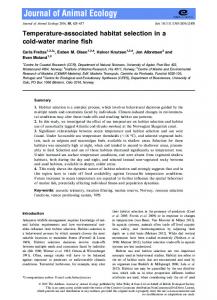
online morphology evolution of the CB/PP was then carried out by using OM. As displayed in Figure 7, in the original sample, obvious light (PP region) and dark region (CB rich region) that are connected with each other (Figure 7a) can be observed clearly, indicating the formation of a segregated conductive network structure. With increasing the temperature to 165 °C (near the Tm of PP matrix), some conductive networks are slightly disrupted (Figure 7b). This should be attributed to the volume expansion resulting from the melting of crystallization region and the Brownian motion of CB particles in the PP melt. According to the electron tunneling effect proposed by Balberg and co-workers,[63,64] a minute increase in gap between the filler particles (or aggregates) will result in the sharp increase of resistivity, that is, the PTC effect thus generates (Figure 3a). When
the temperature is increased to 200 °C, as shown in Figure 8c–e, with increasing the IT time from 0 to 100 min, interestingly, the CB particles gradually migrated into PP matrix adjacent to the interfacial region. After long-time IT for about 150, 185, and 300 min, the CB particles reaggregate together gradually forming a developed conductive network (Figure 7f–h). Finally, when the sample is cooled down to room temperature, conductive path is partially preserved (Figure 7i). More CB particles are joined in the construction of new conductive path, forming much denser conductive path in the composites. The conductive network is thus more resistant to the volume expansion, resulting in the reduction in the IPTC. The detailed online OM observations are shown in Video S1 (Supporting Information). That is, the competition process is demonstrated visually and the variation in IPTC can be understood. Theoretical analysis behind the competition mechanism and the equilibrium time was also revealed. Based on the OM observation, the underlying mechanism behind the evolution of PTC should be ascribed to the diffusion and reaggregation of CB aggregates. Diffusion is always triggered by a gradient of filler concentration. In the present paper, the CB particles are selectively located at the interfaces between PP, showing an obvious concentration gradient. Consequently,
Figure 7. Optical images of the 3.31 vol% CB/PP during the thermal treatment: a) 20 °C before heating; b) 165 °C; c) 200 °C for 0 min; d) 200 °C for 15 min; e) 200 °C for 100 min; f) 200 °C for 150 min; g) 200 °C for 185 min; h) 200 °C for 300 min; i) 20 °C after cooling.
Adv. Mater. Interfaces 2017, 1700265
1700265 (7 of 10)
© 2017 WILEY-VCH Verlag GmbH & Co. KGaA, Weinheim
www.advancedsciencenews.com
www.advmatinterfaces.de
Figure 8. Schematic diagram of morphological development for the motion of CB particles during the thermal treatment. CB particles are represented by the arrows. a) Before heating, b) after short-term thermal treatment, c) after long-term thermal treatment, and d) after cooling to room temperature.
the diffusion driven by the concentration gradient would happen and obeys the second Fick’s second law[65,66] ∂φ ∂2 φ = −D 2 (2) ∂t ∂ x where φ represents the CB aggregation concentration (in terms of volume), D is the diffusion coefficient, while x and t represent dimensions of space and time. For diffusion of spherical nanoparticles in polymer melt, D could be estimated from the Stokes–Einstein’s equation[67–69] D=
kT (3) 6 π Rη
where k is the Boltmann’s constant, T is the temperature, R is the radius of CB particle and η is the viscosity of polymer melt. Substantially, the factor influencing the kinetic process of diffusion is the activation energy (Ea), which is independent on the filler concentration.[22] Thus, the percentage of CB particles in a conductive polymer composite, which have the ability to diffuse, is equivalent. On the other hand, the η increases with the increase of conductive filler concentration,[61,69] which is consistent with the result of graphene nanoplatelet/PP system,[33] resulting in the inhibition of mobility of CB particles. In addition, from the viewpoint of aggregation, higher CB loading leads to a shorter interaggregate gap and an easier agglomeration. Therefore, the higher CB concentration, the weaker diffusion ability for the CB particles; namely, a longer time is needed to reach an equilibrium state. This ρ-T phenomenon is a novel characteristic of this segregated CB/PP with a relatively low melt viscosity.
Adv. Mater. Interfaces 2017, 1700265
After that, in order to reduce the total interfacial energy, the filling particles or aggregates coagulate each other through the Brownian motion, the movement of stretched polymer chains, the dispersive interaction between CB and the matrix as well as the depletion interaction between adjacent CB aggregates.[22,61,67–73] This can be described by Smoluchowski Equation (4)[74] ij i + j →[i + j ] (4)
K
where i and j represent the dispersed filling particle or aggregated particles, Kij is the kinetic constant of the reaction, and [i + j] refer to the new aggregate. The mechanism underlying the PTC effect of CB/PP with a segregated structure can now be understood through the schematic diagram of the microstructural developments during thermal treatment, as shown in Figure 8. A novel segregated conductive network was formed during compression molding (Figure 8a). When subjected to IT, CB particles begin to migrate into PP matrix by Brownian motion. After short-term IT, migration dilutes conductive network, leading to increase in IPTC (see Figures 3b and 5a,c), while after long-term IT, reaggregation of CB particles results in a dense conductive network and therefore a decreased PTC effect. In other words, the attenuation of IPTC is observed after a characteristic time (see Figures 4 and 5).
3. Conclusions Segregated conductive polymer CB/PP composite film was observed to exhibit novel double-peak positive temperature coefficient phenomenon during the heating process. The first PTC peak was attributed to the destruction of the feeble
1700265 (8 of 10)
© 2017 WILEY-VCH Verlag GmbH & Co. KGaA, Weinheim
www.advancedsciencenews.com
www.advmatinterfaces.de
segregated conductive network near the interfacial region due to a small amount of interfacial PP melting, whereas the second PTC peak was because of a large amount of crystal melting of bulk PP matrix. The IPTC of CB/PP increased obviously with increasing the run number. Interestingly, the IPTC first increased then decreased with extending the IT time at 200 °C. Based on the in situ observation of the CB motion profile, the unique segregated morphological evolution was responsible for the anomalous variation of IPTC. With a short-term IT, the gradual migration of CB particles from the interfaces into the PP matrix adjacent to the interfacial region thinned the conductive network. The thin conductive network was more vulnerable to the volume expansion and thereby the improvement in IPTC occurred. The reaggregation of CB particles by Brownian motion formed a perfect conductive network during long-term IT, which resulted in a reduction in IPTC. The present paper is of great value to understand the origin of PTC effect of a segregated CPC through a visual investigation. These CPCs have great potential to be applied for various fields including energy storage/conversation,[75,76] EMI shielding,[77] and sensing.[78,79]
Acknowledgements The authors gratefully acknowledge the financial support of this work by the National Natural Science Foundation (Contract No. 51603193, 11572290, and 11432003), the National Natural Science Foundation of China-Henan Province Joint Funds (Contract No. U1604253), the China Postdoctoral Science Foundation (Contract Nos. 2015M580637 and 2016T90675), Opening Project of State Key Laboratory of Polymer Materials Engineering (Sichuan University) (Contract No. sklpme2016-4-21), and the Special Science Foundation for Excellent Youth Scholars of Zhengzhou University (Contract No. 1421320041). Z.G. appreciates the start-up fund from University of Tennessee.
Conflict of Interest The authors declare no conflict of interest.
Keywords conductive polymer nanocomposites, microscopic observation, PTC effect, segregated structures Received: March 3, 2017 Revised: May 26, 2017 Published online:
4. Experimental Section The used PP (MW = 3.99 × 10⁵ g mol−1, pellets, Petroleum Chemical Co. Xinjiang, China) had molecular weight distribution of ≈4.6 and the MFI of 3.0 g/10 min (230 °C, 2.16 kg). The conductive CB (model VXC-605) was supplied by Cabot with a dibutyl phthalate (DBP) value of 148 ± 15 cm3/100 g and a particle size of ≈30–50 nm (Figure 1i; Figure S1, Supporting Information). Alcohol (AR grade) and xylene (AR grade) were purchased from Zhiyuan Reagent Co., Ltd. Tianjin, China, and used as received. The PP particles were prepared by dissolving-smashing method developed in the lab.[32] The crystallinity of PP is about 55.1 vol% (Figure S2, Supporting Information). For the fabrication of CB/PP with various CB contents (3.31, 3.79, and 4.26 vol%), the CB and PP particles were first mixed and then added into ethanol. Mechanical stirring (for 1 h) and ultrasonication (for another 1 h) were then applied to achieve a well-dispersed filler suspension. After complete evaporation of ethanol, the PP particles coated with CB were obtained. The powder was eventually compression molded into films with a pressure of 15 MPa at 190 °C for 5 min. The fractured surfaces of the sample and PP particles were observed with a 7500F JEOL FESEM. For OM observation with a heating stage, the sample of about 10 µm thick film cut by a microtome was exposed to a thermal program (heated to 200 °C at 2 °C min−1, held this temperature for 300 min, and then cooled to 25 °C at a rate of 2 °C min−1). For TEM observation, ≈100 nm thick composite films were fabricated by a Leica UC-7 microtome with a diamond knife at −120 °C and observed by a JEOL JEM-1230 instrument at 90 kV. The thermal properties were measured by differential scanning calorimetry (TA DSC-2920) at a heating rate of 2 °C min−1 under constant nitrogen flow. The samples were heated from ambient temperature to 200 °C. The sample dimension for the ρ-T tests was 0.6 × 10 × 100 mm3. Copper grid was embedded on both sides of the samples to eliminate contact resistance between the samples and electrodes. The resistance of the samples was recorded continuously by utilizing a megger (model TH2683, supplied by Changzhou Tonghui Electronics Co., Ltd.) coupled with a computer.
Supporting Information Supporting Information is available from the Wiley Online Library or from the author.
Adv. Mater. Interfaces 2017, 1700265
[1] Y. Kim, J. Zhu, B. Yeom, M. Di Prima, X. L. Su, J. G. Kim, S. J. Yoo, C. Uher, N. A. Kotov, Nature 2013, 500, 59. [2] H. Gu, J. Guo, H. Wei, S. Guo, J. Liu, Y. Huang, M. A. Khan, X. Wang, D. P. Young, S. Wei, Z. Guo, Adv. Mater. 2015, 27, 6277. [3] J. Zhu, S. Wei, M. Alexander, T. Dang, T. Ho, Z. Guo, Adv. Funct. Mater. 2010, 20, 76. [4] B. C. K. Tee, C. Wang, R. Allen, Z. N. Bao, Nat. Nanotechnol. 2012, 7, 825. [5] S. Y. Kim, S. Park, H. W. Park, D. H. Park, Y. Jeong, Adv. Mater. 2015, 27, 4178. [6] T. Sekitani, Y. Noguchi, K. Hata, T. Fukushima, T. Aida, T. Someya, Science 2008, 321, 1468. [7] J. Lessing, S. A. Morin, C. Keplinger, A. S. Tayi, G. M. Whitesides, Adv. Funct. Mater. 2015, 25, 1418. [8] H. Liu, Y. Li, K. Dai, G. Zheng, C. Liu, C. Shen, X. Yan, J. Guo, Z. Guo, J. Mater. Chem. C 2016, 4, 157. [9] X. Zhang, X. Yan, Q. He, H. Wei, J. Long, J. Guo, H. Gu, J. Yu, J. Liu, D. Ding, L. Sun, S. Wei, Z. Guo, ACS Appl. Mater. Interfaces 2015, 7, 6125. [10] C. Yang, H. Wei, L. Guan, J. Guo, Y. Wang, X. Yan, X. Zhang, S. Wei, Z. Guo, J. Mater. Chem. A 2015, 3, 14929. [11] Z. Sun, L. Zhang, F. Dang, Y. Liu, Z. Fei, Q. Shao, H. Lin, J. Guo, L. Xiang, N. Yerra, Z. Guo, CrystEngComm. 2017, DOI: 10.1039/ C7CE00279C. [12] L. Gao, E. T. Thostenson, Z. Zhang, T. W. Chou, Adv. Funct. Mater. 2009, 19, 123. [13] C. Zhan, G. Yu, Y. Lu, L. Wang, E. Wujcik, S. Wei, J. Mater. Chem. C 2017, 5, 1569. [14] H. Jin, Q. Chen, Z. Chen, Y. Hu, J. Zhang, CAAI Trans. Intell. Technol. 2016, 1, 104. [15] X. Zhang, H. Gao, M. Guo, G. Li, Y. Liu, D. Li, CAAI Trans. Intell. Technol. 2016, 1, 4. [16] C. Alippi, CAAI Trans. Intell. Technol. 2016, 1, 1. [17] A. Rybak, G. Boiteux, F. Melis, G. Seytre, Compos. Sci. Technol. 2010, 70, 410.
1700265 (9 of 10)
© 2017 WILEY-VCH Verlag GmbH & Co. KGaA, Weinheim
www.advancedsciencenews.com
www.advmatinterfaces.de
[18] S. P. Bao, G. D. Liang, S. C. Tjong, Carbon 2011, 49, 1758. [19] A. Kono, K. Shimizu, H. Nakano, Y. Goto, Y. Kobayashi, T. Ougizawa, H. Horibe, Polymer 2012, 53, 1760. [20] I. S. Gunes, G. A. Jimenez, S. C. Jana, Carbon 2009, 47, 981. [21] S. Isaji, Y. Bin, M. Matsuo, Polymer 2009, 50, 1046. [22] G. Z. Wu, S. Asai, M. Sumita, Macromolecules 2002, 35, 1708. [23] C. Zhang, C. A. Ma, P. Wang, M. Sumita, Carbon 2005, 43, 2544. [24] H. Deng, T. Skipa, E. Bilotti, R. Zhang, D. Lellinger, L. Mezzo, Q. Fu, I. Alig, T. Peijs, Adv. Funct. Mater. 2010, 20, 1424. [25] J. W. Zha, W. K. Li, R. J. Liao, J. B. Bai, Z. M. Dang, J. Mater. Chem. 2013, 1, 843. [26] J. Y. Feng, C. M. Chan, Polymer 2000, 41, 7279. [27] H. Pang, Y. C. Zhang, T. Chen, B. Q. Zeng, Z. M. Li, Appl. Phys. Lett. 2010, 96, 251907. [28] K. Dai, Z. M. Li, X. B. Xu, Polymer 2008, 49, 1037. [29] I. Mironi-Harpaz, M. Narkis, J. Polym. Sci. Part B: Polym. Phys. 2001, 39, 1415. [30] C. Zhang, L. Wang, J. Wang, C. A. Ma, Carbon 2008, 46, 2053. [31] Q. Zheng, Y. H. Song, G. Wu, X. B. Song, J. Polym. Sci. Part B: Polym. Phys. 2003, 41, 983. [32] K. Dai, S. Zhao, W. Zhai, G. Zheng, C. Liu, J. Chen, C. Shen, Composites, Part A 2013, 55, 11. [33] A. P. Bafana, X. Yan, X. Wei, M. Patel, Z. Guo, S. Wei, E. K. Wujcik, Composites, Part B 2017, 109, 101. [34] Q. He, T. Yuan, X. Zhang, X. Yan, J. Guo, D. Ding, M. A. Khan, D. P. Young, A. Khasanoy, Z. Luo, J. Liu, T. D. Shen, X. Liu, S. Wei, Z. Guo, J. Phys. Chem. C 2014, 118, 24784. [35] Y. Li, J. Zhu, S. Wei, J. Ryu, Q. Wang, L. Sun, Z. Guo, Macromol. Chem. Phys. 2011, 212, 2429. [36] J. M. Thomassin, M. Trifkovic, W. Alkarmo, C. Detrembleur, C. Jerome, C. Macosko, Macromolecules 2014, 47, 2149. [37] V. H. Pham, T. T. Dang, S. H. Hur, E. J. Kim, J. S. Chung, ACS Appl. Mater. Interfaces 2012, 4, 2630. [38] D. X. Yan, H. Pang, B. Li, R. Vajtai, L. Xu, P. G. Ren, J. H. Wang, Z. M. Li, Adv. Funct. Mater. 2015, 25, 559. [39] J. C. Grunlan, A. R. Mehrabi, M. V. Bannon, J. L. Bahr, Adv. Mater. 2004, 16, 150. [40] G. A. Gelves, M. H. Al-Saleh, U. Sundararaj, J. Mater. Chem. 2011, 21, 829. [41] C. J. Capozzi, R. A. Gerhardt, Adv. Funct. Mater. 2007, 17, 2515. [42] F. Kohler, U.S. Patent 3243753, 1966. [43] H. P. Xu, Z. M. Dang, M. J. Jiang, S. H. Yao, J. Bai, J. Mater. Chem. 2008, 18, 229. [44] S. Jose, A. S. Aprem, B. Francis, M. C. Chandy, P. Werner, V. Alstaedt, S. Thomas, Eur. Polym. J. 2004, 40, 2105. [45] M. Trujillo, L. Arnal, A. J. Mullwe, Macromolecules 2008, 41, 2087. [46] B. P. Grady, F. Pompeo, R. L. Shambaugh, D. E. Resasco, J. Phys. Chem. B 2002, 106, 5852. [47] Y. Li, U. Sundararaj, AIChE J. 2015, 61, 296. [48] X. Y. Li, F. M. Su, Y. X. Ji, N. Tian, J. Lu, Z. Wang, Z. M. Qi, L. B. Li, Soft Matter 2013, 9, 8579. [49] M. Hindermann-Bischoff, F. Ehrburger-Dolle, Carbon 2001, 39, 375. [50] T. M. Wu, J. C. Cheng, M. C. Yan, Polymer 2003, 44, 2253.
Adv. Mater. Interfaces 2017, 1700265
[51] H. Deng, T. Skipa, R. Zhang, D. Lellinger, E. Bilotti, I. Alig, T. Peijs, Polymer 2009, 50, 3747. [52] G. S. Chen, B. Yang, S. Y. Guo, J. Appl. Polym. Sci. 2008, 114, 1848. [53] C. M. Chan, C. L. Cheng, N. M. F. Yuen, Polym. Eng. Sci. 1997, 37, 7. [54] H. Pang, D. X. Yan, Y. Bao, J. B. Chen, C. Chen, Z. M. Li, J. Mater. Chem. 2012, 22, 23568. [55] M. O. Lisunova, Y. P. Mamunya, N. I. Lebovka, A. V. Melezhyk, Eur. Polym. J. 2007, 43, 949. [56] H. Nakano, K. Shimizu, S. Takahashi, A. Kono, T. Ougizawa, H. Horibe, Polymer 2012, 53, 6112. [57] Y. Fang, J. Zhao, J. W. Zha, D. R. Wang, Z. M. Dang, Polymer 2012, 53, 4871. [58] T. Natsuki, Q. Q. Ni, S. H. Wu, Polym. Eng. Sci. 2008, 48, 1345. [59] D. Ren, S. Zheng, S. Huang, Z. Liu, M. Yang, J. Appl. Polym. Sci. 2013, 129, 3382. [60] Q. Li, Siddaramaiah, N. H. Kim, G. H. Yoo, J. H. Lee, Composites, Part B 2009, 40, 218. [61] G. Z. Wu, S. Asai, C. Zhang, T. Miura, M. Sumita, J. Appl. Phys. 2000, 88, 1480. [62] X. L. Tao, Y. Pan, Q. Zheng, X. S. Yi, J. Appl. Polym. Sci. 2001, 79, 2258. [63] Z. Rubin, S. A. Sunshine, M. B. Heaney, I. Bloom, I. Balberg, Phys. Rev. B 1999, 59, 12196. [64] O. Wolf, M. Dasog, Z. Yang, I. Balberg, J. G. C. Veinot, O. Millo, Nano Lett. 2013, 13, 2516. [65] A. Fick, Ann. Phys. Chem. 1855, 94, 59. [66] B. Watts, W. J. Belcher, L. Thomsen, H. Ade, P. C. Dastoor, Macromolecules 2009, 42, 8392. [67] L. B. Lurio, D. Lumma, A. R. Sandy, M. A. Borthwick, P. Falus, S. G. J. Mochrie, Phys. Rev. Lett. 2000, 84, 785. [68] J. Liu, D. Cao, L. Zhang, J. Phys. Chem. C 2008, 112, 6653. [69] P. E. M. Allen, C. R. Patrick, Kinetics and mechanisms of polymerization reactions, Halsted Press, New York 1974. [70] Q. Cao, Y. H. Song, Y. Q. Tan, Q. Zheng, Polymer 2009, 50, 6350. [71] M. Sumita, S. Asai, N. Miyadera, E. Jojima, K. Miyasaka, Colloid. Polym. Sci. 1986, 264, 212. [72] N. Grossiord, P. J. J. Kivit, J. Loos, J. Meuldijk, A. V. Kyrylyuk, P. Van der Schoot, C. E. Koning, Polymer 2008, 49, 2866. [73] J. G. Meier, J. W. Man, M. Klüppel, Phys. Rev. B 2007, 75, 054202. [74] R. Jullien, R. Botet, Aggregation and fractal aggregates, World Scientific, Singapore 1987. [75] H. Wei, H. Gu, J. Guo, X. Yan, J. Liu, D. Cao, X. Wang, S. Wei, Z. Guo, Adv. Compos. Sci. 2017. [76] H. Wei, Y. Wang, J. Guo, N. Shen, D. Jiang, X. Zhang, X. Yan, J. Zhu, Q. Wang, L. Shu, H. Lin, S. Wei, Z. Guo, J. Mater. Chem. A 2015, 3, 469. [77] K. Zhang, H. Yu, Y. Shi, Y. Chen, J. Zeng, J. Guo, B. Wang, Z. Guo, M. Wang, J. Mater. Chem. C 2017, 5, 2807. [78] T. Gong, M. Liu, H. Liu, S. Peng, T. Li, R. Bao, W. Yang, B. Xie, M. Yang, Z. Guo, Polymer 2017, 110, 1. [79] H. Liu, M. Dong, W. Huang, J. Gao, K. Dai, J. Guo, G. Zheng, C. Liu, C. Shen, Z. Guo, J. Mater. Chem. C 2017, 5, 73.
1700265 (10 of 10)
© 2017 WILEY-VCH Verlag GmbH & Co. KGaA, Weinheim