IEEE TRANSACTIONS ON POWER ELECTRONICS, VOL. 20, NO. 6, NOVEMBER 2005
1303
Power Budgeting of a Multiple-Input Buck-Boost Converter Nicholas D. Benavides, Student Member, IEEE, and Patrick L. Chapman, Senior Member, IEEE
Abstract—The use of a multiple-input buck-boost converter for budgeting power between different energy sources is discussed. It is shown mathematically that the idealized converter can accommodate arbitrary power commands for each input source while maintaining a prescribed output voltage. Power budgeting is demonstrated experimentally for a real converter under various circumstances, including a two-input (solar and line-powered) system. A closed-loop control example involving simultaneous tracking of output voltage and set-point tracking of the solar array shows that an autonomous system is realizable. Index Terms—Closed-loop control, buck-boost converter, solar array.
multiple-input
(MI)
I. INTRODUCTION
A
MULTIPLE-INPUT (MI) converter is a circuit that accommodates input of more than one energy source and provides at least one output. Such technology can find application in residential, aerospace, automotive, portable electronics, and any other application where there is the possibility of using more than one source. By diversifying the energy source, alternative energy can be better utilized, reliability can be increased, and the most readily available energy sources (whatever they are at a given location, time of day, or cost) can be taken advantage of. This paper presents an analysis of one general MI converter topology that can facilitate many applications. Here, we begin by reviewing some previous MI converters and comparing to the proposed circuits. The authors of [1] developed an MI converter that involved a transformer in which there was a separate winding for each input (Fig. 1). The converter also accommodated multiple-outputs (MOs) by using multiple secondary windings. The converter was somewhat like using multiple flyback converters in parallel, except the transformers for each converter are combined on one core. This enables any input to provide energy to any output, and provides electrical isolation to all inputs and outputs. Despite these advantages, the transformer core must be suitably large to accommodate all of these windings and if only one output is required, this advantage is partially mitigated. The authors demonstrate their work successfully on a two-input system involving solar cells and utility inputs. Steady-state and dynamic characteristics were investigated. In [2], the work is extended to show maximum power point tracking and power factor could also be involved. Manuscript received November 9, 2004; revised March 16, 2005. This work was supported by the U.S. National Science Foundation under Grant ECS-0134208. Recommended by Associate Editor J. Cobos. The authors are with the University of Illinois at Urbana-Champaign, Urbana, IL 61801 USA (e-mail:
[email protected]). Digital Object Identifier 10.1109/TPEL.2005.857531
Fig. 1. MIMO converter from [1].
Fig. 2. MI boost converter from [3]. MOs are possible by adding more legs.
In [3], another MI topology was developed (Fig. 2). This topology consists of a standard inverter phase leg connected to a dc bus capacitor, wherein more phase legs can be paralleled to accommodate more sources. The switches in Fig. 2 are bidirectional-conducting, forward-blocking (BCFB); i.e., normally an IGBT or MOSFET with an antiparallel diode. Each phase leg is coupled through an inductor to an energy source. The switches in the phase legs are controlled to regulate the amount of power flowing from each. The dc bus is charged by the input sources and used to supply an inverter and motor drive in an automotive application. The system was demonstrated on a prototype that involves three different energy sources. When power flows from a source, the corresponding converter cell is essentially a set of boost converters sharing a common capacitor with other cells. With power flow to a source, the capacitor supplies the cell as a buck converter. Advantages include bidirectional power flow to and from sources, and possible use of standard phase leg packages. A disadvantage is that more parts than necessary are used if the inputs are not bidirectional (e.g. fuel cells, primary batteries, solar cells, etc.), although certain devices could be eliminated without adversely affecting the circuit in these cases. An-
0885-8993/$20.00 © 2005 IEEE
1304
Fig. 3.
IEEE TRANSACTIONS ON POWER ELECTRONICS, VOL. 20, NO. 6, NOVEMBER 2005
Two-input buck converter from [5]. Fig. 5. Proposed MI buck-boost converter.
Fig. 4. Two-input buck converter from [6]. More inputs possible by adding more FCBB switches as appropriate.
other possible disadvantage is the need for an inductor for each phase leg, which can involve a high cost, high mass, and issues with scaling to more inputs. In [4], a similar topology, but simplified with paralleled boost converters only instead (i.e., the BCFB switches of Fig. 2 are reduced to simpler switches, as appropriate), was previously presented in the context of combined wind and photovoltaic systems. This system reduces the parts count by eliminating the bidirectional capability. In [5], a two-input buck converter is presented that is proposed as an efficient solution to a dc-dc post regulation problem. This converter, pictured in Fig. 3, is an ordinary buck converter but with a battery (or other dc source) placed in series with the diode. While this does not scale to more inputs, it is effective for the proposed application. In Fig. 4, another two-input buck converter is shown as proposed in [6]. This topology scales to more inputs as needed, but of course like [5], is only capable of buck operations, which may be all that is needed in some applications. The converter presented herein has its own advantages and disadvantages compared to the converters in [1]–[6]. The proposed converter has a small parts count (both semiconductor, passive, and sensing) and scales to MIs. The converter provides either buck or boost transformation of the inputs. However, it does not provide isolation between inputs, though isolation among outputs and inputs is optional. Bidirectional power flow to and from sources can be done extrinsically by using another converter connected from the output back to an input or by using the isolated MO rendering where some outputs are used to feed back to some inputs. For a range of input sources, this converter is very satisfactory. Several sources, for example, are flexible in their isolation (batteries, for example). This converter topology was introduced briefly by the authors in [7]. We extend [7] by presenting the converter topology, its derivatives, and more extensive analysis and experimentation. We show the converter used in several experimental contexts. From [7], it was not immediately obvious that the converter would be effective at budgeting power among different
Fig. 6.
Proposed MIF converter.
input sources without sacrificing control of the output voltage. Here, we show that it is possible to budget power arbitrarily while maintaining prescribed output voltage. This is illustrated in hardware using a manually controlled bench-top three-input system. To further support the analysis a two-input system consisting of a solar array and line-power dc input is also shown. This will show that power budgeting is also possible coming from sources that have varying voltage. A closed-loop example for the latter case is also shown that demonstrates simultaneous output tracking and maximum power point tracking of the solar array. More development of automatic closed-loop control requires extensive analysis and is left for future work. II. REVIEW OF CONVERTER AND ITS DERIVATIVES Following the work in [7], the proposed circuit topology is shown in Fig. 5. As shown, it is an MI buck-boost (MIBB) coninput voltage sources , verter. It is fed from input currents, . The output which drive the supplies the output current to the load (not voltage shown). The passive components are inductor and capacitor . On the output side, a diode , is used. On the input side, a forward-conducting, bidirectional-blocking (FCBB) switch is . An FCBB switch can required on each input be a gate turn-off thyristor (GTO) or a transistor in series with a diode. Recently, some semiconductor manufacturers have offered reverse-blocking (RB) insulated-gate bipolar transistor (IGBTs) that can achieve the same on-state voltage typical of an ordinary IGBTs. If it is known that some input voltage is always higher than the others, then need only be a forward-conducting, forward-blocking (FCFB) switch, such as an IGBT. The MIBB has an inverted, nonisolated output with respect to the inputs. A derivative of the MIBB can be obtained by replacing the inductor in Fig. 5 with coupled inductors to form the circuit in Fig. 6. This provides isolation and thus the ability to use a noninverted output. The circuit in Fig. 6 resembles a flyback converter.
BENAVIDES AND CHAPMAN: POWER BUDGETING OF A MULTIPLE-INPUT BUCK-BOOST CONVERTER
Fig. 7.
1305
Proposed MIMO flyback converter.
As such, it is denoted the MI flyback (MIF) topology. The analysis of the MIF is similar to the MIBB, except for a turns-ratio factor scaling the output voltage and leakage inductance considerations. This analysis is the subject of ongoing work [8]. Another derivative of the MIBB results by using multiple transformer secondary windings in the MIF topology: the multipleinput, multiple-output, flyback (MIMOF) topology (Fig. 7). The MIMOF provides isolation among MOs, and can be used to route power from any input to any output. An output (a battery, for example) can be connected to an input to achieve bidirectional flow. Though more general than the MIF or MIBB converters, the MIMOF also remains a subject of continuing work. This family of power converters is most similar to that presented in [1] (Fig. 1). The key difference being that the multiple primary windings used in Fig. 1 are absent in Figs. 5–7. While the primary windings can retain isolation among inputs, this is not necessarily a disadvantage of the MIBB. Most systems will allow the input sources to share a common ground. However, if the input voltage magnitudes are substantially different, the use of primary windings with different numbers of turns could be beneficial. If retaining isolation among inputs and substantial adjustment of the input voltages via turns ratios indeed are not necessary, then reduction of the primary windings to a single winding is a significant cost, mass, complexity, and size improvement. Furthermore, if sensing the input currents, the MIBB requires only one sensor on the inductor current from which each input current can be determined logically from known switching states. In reality, for any particular energy diversification problem, several converter circuits must be evaluated to determine which is best. III. CONTINUOUS MODE MIBB
Fig. 8.
Switch control scheme used in model development.
Consider a duty cycle control scheme where each switch switches at the same frequency and the leading edge of each coincides (Fig. 8). The trailing edges do not gate signal . Then coincide, as each switch has a different duty cycle (1) simplifies to (2) where is the effective duty cycle of each switch; that is, the portion of time the switch conducts nonzero current. If the voltage indices are arbitrarily ordered such that , then
(3)
The average inductor current, assuming no power loss, is equal to (4)
To approximate the inductor current ripple, the time constant is assumed to be long compared to the period , and the charging is assumed to be linear. The portion of the current ripple seem by each input is
A. Formulae for Steady-State Operation
(5)
This section summarizes the results from [7]. In the analysis to follow, a capital letter designates the dc, steady-state value of a signal. Likewise, a lowercase letter designates a dynamic signal. If the inductor current is strictly positive in the steadystate, continuous conduction mode results. This guarantees that at least one FCBB switch or the diode is conducting at all times. Assigning the switching signals with binary values and assuming ideal switches, the average output voltage is
and the total peak-to-peak inductor current ripple is the sum of these ripple components (6). The input ripple components calculated here are not the actual input current ripple, as the input current ripple is discontinuous (6) The peak inductor current is estimated geometrically to be
(1) (7)
1306
IEEE TRANSACTIONS ON POWER ELECTRONICS, VOL. 20, NO. 6, NOVEMBER 2005
The peak current can then be used to find the average current of each input, using a geometric approach. The peak current seen by each input is the peak inductor current minus the ripple seen by each input which conducts after it in the cycle (8) The average current over the entire cycle is the average current over this conduction interval, adjusted by the duty cycle for which the interval occurs (9) The power supplied by each input (10) is the product of the input voltage and input current
(10)
B. Calculation of Duty Cycles In order to budget the power, we must be able to specify any 0 and be able to regulate the output voltage a given . Simultaneously, the sum of the powers input must add to (assuming 100% efficiency, as we the power output have thus far in the development). Therefore, (10) should be 1. With substitution of (2) and written for from one to , (10) becomes
Fig. 9. Discontinuous mode current example.
tion. The solution must be tested to prove all effective duty cycles are greater than zero and their sum is less than one. While (11) and (12) do not have a readily obtained closed-form solution that can be used to perform this test, we have yet to find a case that did not pass once the equations are solved numerically. Experimental results below confirm this for a few cases. For the special case of large values of , it is possible to prove a unique and practical solution always exists. If power loss is considered, a loss term can be added to the left hand side of (12). This term would generally be a complicated function of parameters and duty cycle, but would not add degrees of freedom. Therefore a lossy converter will also have a solution to the power budgeting problem. This is also confirmed below experimentally. In nearly any application, the duty cycle would normally by determined by feedback control in a practical circuit, just as in almost any other dc-dc converter. The preceding discussion is only meant to show that it is possible to find a set of duty cycle commands that allow simultaneous power budgeting and output voltage regulation in continuous mode. IV. DISCONTINUOUS MODE MIBB A. Formulas for Steady-State Operation Summarizing the results of [7], we present the idealized formulas for discontinuous mode. Only one switch conducts at a time. Assuming the time constant of the inductor is large compared to the period, the change in inductor current during the interval is
(11) Power balance requires the
(13)
th equation be where is the period. The total change in current in the positive direction is the sum of all (see Fig. 9). Since in discontinuous mode, the current starts from zero each cycle (14) (12) Assuming a resistive load tions and manipulations
The nonlinear system of equations and unknowns must be solved to determine the duty cycle commands. Except in spurious cases of singularity, (11) and (12) assure at least one solu-
, and performing several substitu-
(15)
BENAVIDES AND CHAPMAN: POWER BUDGETING OF A MULTIPLE-INPUT BUCK-BOOST CONVERTER
1307
Equation (15) is very sensitive to parameters as we generally expect for discontinuous mode. The average current of each input is the same as the continuous conduction mode, except that the formula for the peak inductor current is much simpler
(16) The power supplied by each input (17) is the product of the input voltage and input current
Fig. 10.
MIBB hardware realization.
(17) TABLE I LINE SUPPLIED POWER BUDGETING
B. Calculation of Duty Cycles for Discontinuous Mode Power Budgeting The power budgeting problem in discontinuous mode is simpler than continuous mode because the average power supplied by each input does not depend on the output power
(18) In this case, the output voltage will be whatever is needed to dissipate this power, therefore the equation is (19) As long as the duty cycles are continuously defined, it is possible to control the distribution of power over the input sources. Discontinuous mode is not examined experimentally in this work, but the duty cycles are always lower than continuous mode for a given output voltage, and can therefore be easily implemented. V. EXPERIMENTAL DATA An example MIBB converter was constructed to confirm that power budgeting can be accomplished independent of the output voltage (Fig. 10). The FCBB switches are realized using a MOSFET (IRFB260N, series resistance 40 m ) in series with a diode (DSEK60_06, forward drop 1.5 V). The output diode was also a DSEK60_06. The components were chosen to allow a robust converter in the 100 to 250 W output power range, and were not optimized for efficiency. A 98.6 H inductor was wound on a Micrometals [9] T300D-26 core to support an inductor current of 30 A. The output capacitor was a 63-V 470- F electrolytic. Filter capacitors (470 F) were also placed on each input, to smooth the current drawn from the sources. The test cases explored are limited to continuous conduction mode (CCM) for brevity and not by any converter limitation.
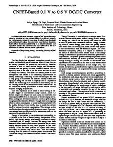
The first power budgeting experiment was to test the concept. Three regulated dc supplies were used as inputs, at 48 V, 30 V, and 24 V. The output voltage desired was 24 Vdc into a resistive (5 ) load at 115 W. The duty cycle of each input was adjusted manually until the steady state output voltage was 24 V, and the desired power budget was attained. Three trials were run, with each source providing 50% of the power in one trial, and the remaining power split evenly between the other two inputs (Table I). These are example cases; any percent can be prescribed from each source. It can be seen that each input can be separately controlled to provide the prescribed amount of power while output voltage remains at 24 V. The analytically calculated values in Table I were found using the equations for an ideal converter derived above. There is less than 10% error in the measured values. The error is caused largely by the losses in the input switches and diodes. These numbers confirm that power budgeting with output voltage regulation is indeed possible, despite nonideal converter operation. The error in the output voltage is caused by a lack of precision in the potentiometers setting the duty cycles, and can be remedied with a closed loop control. The current waveform (Ch. 4) can be seen to have four different slopes (Fig. 11), three charging slopes corresponding to the different input voltages, and one discharge slope determined by the output voltage. The switching functions are also shown (Ch. 1–3) with the channel corresponding to the input. The ver-
1308
IEEE TRANSACTIONS ON POWER ELECTRONICS, VOL. 20, NO. 6, NOVEMBER 2005
Fig. 13.
Power supplied by each source.
Fig. 14.
Output voltage versus percent solar power.
Fig. 11. Example waveforms from trial 1.
Fig. 12. Simple power budgeting control.
tical offset in the switching functions is used to separate them for easier viewing, Ch. 1 being the lowest. To better demonstrate power budgeting, a closed loop regulating control was desired. A solar panel was used with a rectified line source to demonstrate the converter with nonideal sources. A simple control was developed which contained two independent proportional-intregral (PI) controllers (Fig. 12). The first PI loop adjusts the duty-cycle of the line source, to track a reference output voltage. The second PI loop has a much slower time constant, and adjusts the duty-cycle of the solar input to track a reference input voltage. This provides a quick approximation to the maximum power point [10]. The control gains were chosen to give a slow response, leaving advanced control design to future work. This control cannot regulate the output voltage if the solar panel is able to provide more power than required by the load. It will continue to try to draw the panel voltage down to a reference, even if the line source is not being used at all, and the output voltage will rise as needed to dissipate the power from the solar panel. The solar panel used was rated at 120 W, with an open circuit voltage of around 18 V. In our test mount, facing south with approximately a 45 tilt, the best case power output was 65 W. The load was 115 W, therefore the simple control was sufficient. The line source was chosen as 30 V to provide a significant difference between the input voltages. Data were collected at sample
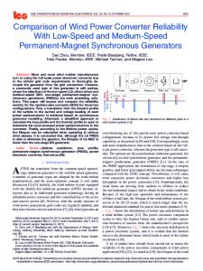
Fig. 15. Efficiency versus percent solar power.
points throughout a day, providing different levels of illumination. The data points have been reordered into increasing solar power. (Fig. 13) The output voltage was regulated to 24 V at all sample points as shown in (Fig. 14). The solar input voltage was driven to 15 V by the second PI loop. The efficiency of the converter (Fig. 15) is reduced when more power is supplied by the solar panel, but this occurs because the solar panel voltage is
BENAVIDES AND CHAPMAN: POWER BUDGETING OF A MULTIPLE-INPUT BUCK-BOOST CONVERTER
half the voltage of the line source input, and therefore the currents are twice as high. A dominating loss mechanism in this converter is the forward voltage drop of the input diodes; therefore this drop in efficiency with lower voltage sources is expected. VI. CONCLUSION In this work, an example of power budgeting in a MI buckboost converter was presented. It was shown mathematically to be possible in an ideal converter, and then tested in experiment. The control design was not intended to be exhaustive, but to show that the converter topology enables even simple controls to perform the task. A real world example was shown using solar cell input and a line rectified backup source. Simple PI controls were able to regulate the output voltage, while tracking an approximation to the maximum power output of the solar panel. REFERENCES [1] H. Matsuo, K. Kobayashi, Y. Sekine, M. Asano, and L. Wenzhog, “Novel solar cell power supply system using the multiple-input dc-dc converter,” in Proc. 20th Int. Telecommunications Energy Conf. (INTELEC’98), 1998, pp. 797–802. [2] H. Matsuo, T. Shigemizu, F. Kurokawa, and N. Watanabe, “Characteristics of the multiple-input dc-dc converter,” in Proc. 24th Annu. IEEE PESC’93, 1993, pp. 115–120. [3] A. Di Napoli, F. Crescimbini, L. Solero, F. Caricchi, and F. G. Capponi, “Multiple-input dc-dc power converter for power-flow management in hybrid vehicles,” in Proc. 37th Annu. IEEE Industry Applications Conf., 2002, pp. 1578–1585. [4] F. Caricchi, F. Crescimbini, O. Honorati, A. D. Napoli, and E. Santini, “Testing of a new dc/dc converter topology for integrated wind-photovoltaic generating systems,” in Proc. 5th Eur. Conf. Power Electronics Applications, vol. 8, 1993, pp. 83–88. [5] J. Sebastian, P. J. Villegas, F. Nuno, and M. M. Hernando, “High-efficiency and wide-bandwidth performance obtainable from a two-input buck converter,” IEEE Trans. Power Electron., vol. 13, no. 4, pp. 706–717, Jul. 1998. [6] F. D. Rodriguez and W. G. Imes, “Analysis and modeling of a two-input dc/dc converter with two controlled variables and four switched networks,” in Proc. 31st Intersoc. Energy Conversion Engineering Conf., 1996, pp. 11–16.
1309
[7] B. G. Dobbs and P. L. Chapman, “A multiple-input dc-dc converter,” IEEE Power Electron. Lett., vol. 1, no. 1, pp. 6–9, Mar. 2003. [8] N. Benavides and P. L. Chapman, “Object-oriented modeling of a multiple-input multiple-output flyback converter in Dymola,” in Proc. 2004 IEEE Workshop Computers Power Electronics, 2004, pp. 156–160. [9] Micrometals, Inc. (2005) Iron powder cores. Tech. Rep. [Online] Available: http://www.micrometals.com [10] J. J. Schoeman and J. D. van Wyk, “A simplified maximal power controller for terrestrial photovoltaic panel arrays,” in Proc. 13th Annu. IEEE Power Electronics Specialists Conf., 1982, pp. 361–367.
Nicholas D. Benavides (S’00) was born in St. Louis, MO, on August 17, 1981. He received the B.S.E.E. degree from the University of Missouri-Rolla in 2003 and the M.S.E.E. degree from the University of Illinois at Urbana-Champaign (UIUC), Urbana, in 2004 where he is currently pursuing the Ph.D. degree in electrical engineering. He was a Research Assistant with the University of Missouri-Rolla from 2001 to 2003. He is currently a Research Assistant at UIUC. Mr. Benavides received the Grainger Award for Outstanding Power Engineering Students in 2003 and 2005.
Patrick L. Chapman (S’94–M’96–SM’05) received the B.S.E.E. and M.S.E.E. degrees from the University of Missouri-Rolla, in 1996 and 1997, respectively, and the Ph.D. degree from Purdue University, West Lafayette, IN, in 2000. Currently, he is an Assistant Professor in the Department of Electrical and Computer Engineering, University of Illinois at Urbana-Champaign, Urbana. He is Associate Director of the Grainger Center for Electric Machinery and Electromechanics. He conducts research and teaching activities in power electronics, electric machinery, and electric drives. Dr. Chapman received the National Science Foundation CAREER Award and the Office of Naval Research Young Investigator Award. He is Associate Editor of the IEEE POWER ELECTRONICS LETTERS and is President of the Power Engineering Society Chapter of the Central Illinois section.