882
IEEE TRANSACTIONS ON VEHICULAR TECHNOLOGY, VOL. 53, NO. 3, MAY 2004
Power-Efficient Multispot-Diffuse Multiple-Input–Multiple-Output Approach to Broad-Band Optical Wireless Communications Svetla Jivkova, B. A. Hristov, and Mohsen Kavehrad, Fellow, IEEE
Abstract—In multispot-diffuse multiple-input–multiple-output (MSD-MIMO) system configuration, a communications channel can be considered virtually ideal at data rates of hundreds of megabits per second. Thus, the main concern is power efficiency. We propose a transceiver optical design that creates a reconfigurable transmitter output and independent communications channels. The transmitter employs multiple light sources that can be turned on and off, independently. In this way, an optical signal is provided only where it is needed. The receiver utilizes an imaging optical system and a segmented photodetector, thus performing direction diversity reception. We show that when maximum ratio combining is employed on the received electric signals and power-efficient modulation schemes such as L-level pulse-position modulation are used, significant power savings can be achieved. We also investigate the vulnerability of MSD-MIMO links to shadowing and blockage and their effects on communications cell size and required transmit power in a cellular configuration. Index Terms—Infrared local area networks (LANs), optical wireless communications, transceiver design.
To help the readers, we provide a list of notations used throughout the paper: Transmitter. Receiver. Diffusing spot. Transmitter semi-angle of radiation. Communication cell height. Communication cell-floor radius. Receiver semi-angle of reception. Radius of the circular area on the ceiling within receiver FOV. Transmitter–receiver distance. Transmitter–obstacle distance. Minimum transmitter–obstacle distance at which not all of the transmitter beams that produce diffusing spots within receiver FOV are blocked due to the obstacle height. Minimum transmitter-obstacle distance at which not all of the transmitter beams that produce diffusing Manuscript received May 13, 2003; revised November 28, 2003 and January 4, 2004. S. Jivkova and B. A. Hristov are with the Central Laboratory of Optical Storage and Processing of Information, Bulgarian Academy of Sciences, Sofia 113, Bulgaria (e-mail:
[email protected]). M. Kavehrad is with The Pennsylvania State University, Center for Information and Communications Technology Research (CICTR), Department of Electrical Engineering, University Park, PA 16802 USA (e-mail:
[email protected]). Digital Object Identifier 10.1109/TVT.2004.825779
spots within receiver field-of-view are blocked due to the width of the obstacle. Obstacle height measured from the communication cell floor. Obstacle lateral dimension. Optical signal wavelength. Optical filter spectral bandwidth. Optical filter effective refractive index. I. INTRODUCTION
T
HERE are two major challenges that researchers encounter when working on optical wireless local area networks (LANs) for indoor use. First, infrared is diffusely scattered by most of the interior of an office [1]. Thus, signals reach a receiver after multiple reflections off the room walls and furniture. The immense number of signal paths lead to temporal dispersion and signal distortion and, as a consequence, may cause intersymbol interference. The second major issue is power efficiency. Indoor optical wireless systems are intended to connect portable terminals to backbone global network, as well as to provide means for communications among portables in an office. This implies that the communication system must work at rather low power levels. Also, transceivers must be eye-safe; this requirement also restricts the amount of optical power that can be launched [2]. A multispot-diffuse multiple-input–multiple-output (MSD-MIMO) system [3] is a hybrid configuration that combines features of classical diffuse and line-of-sight (LoS) links in order to combine their advantages. In a MSD-MIMO configuration, the transmitter emits multiple narrow beams that shine small areas, called diffusing spots, on the room ceiling. Then, the optical signal is received by a multiple-element direction diversity receiver from several diffusing spots that lie within the receiver field- of view. The base station and portable units have identical designs and are placed at a desktop level; thus, MSD-MIMO is naturally suited for ad hoc networking as well. When properly designed, MSD-MIMO links are virtually free from multiple-path signal distortion because the major portion of signal power is received via a single path, which is the LoS between a diffusing spot and the receiver. We have shown that the communications channel exhibits a vast bandwidth (greater than 2 GHz on a 3-dB basis) and can be considered virtually ideal at data rates of hundreds of megabits per second [4]. Therefore, the main concern is power efficiency. Since MSD-MIMO
0018-9545/04$20.00 © 2004 IEEE
JIVKOVA et al.: POWER-EFFICIENT MSD MIMO APPROACH
links use diffuse reflections off the room ceiling, the required power is relatively high. On the other hand, the launched power is restricted by eye-safety requirements and power-consumption considerations. There are two major approaches to improving link power budget, namely transceiver design and signaling schemes. This paper focuses on transceiver design issues. Two signaling schemes, ON–OFF keying (OOK) and -level pulse-position modulation (L-PPM), are only used as a means for estimating the link power requirements. To the best of our knowledge, only two basic transmitter designs have been proposed for use in MSD-MIMO systems. One of these uses a single laser source whose output is properly shaped to form an array of diffusing spots on a remote reflecting surface [4], [5]. This is achieved using a holographic or diffractive optical element. The second design employs several infrared light sources aiming appropriate directions [6]. Each of the sources has a lens system to ensure a narrow (almost collimated) light beam that creates a single diffusing spot upon diffuse reflection off the room surfaces. The compactness of the first design is attractive, while the appeal of the second is the possibility of independently driving each diffusing spot and, thus, increasing the system capacity by launching different information streams through different diffusing spots. Lately, vertical-cavity surface-emitting laser diodes (VCSEL) are being recognized as the best choice for a laser source for telecommunications due to their circular output beam and the convenience of manufacturing one-dimensional (1-D) and two-dimensional (2-D) VCSEL arrays. Recently, VCSEL arrays have been employed at the transmitter in LoS cellular and tracked optical wireless architectures [7]–[9]. There, the VCSEL array output is shaped to form communication microcells. Each microcell is illuminated by a single VCSEL from the transmitter array. The two major challenges in this design are the uniform illumination of the microcells and the large deflection angles needed to ensure a good coverage area. In this paper, we adopt the idea of using a VCSEL array as transmitting sources and apply it to MSD-MIMO communication configuration. Unlike as in the LoS architectures, there is no need of individual laser beam profile flattening in MSD-MIMO, because the optical power is confined in a small area diffusing spot. This feature greatly simplifies the optical design. However, the large deflection angles needed are still a challenge that must be faced in MSD-MIMO, too. Regarding the receiver in MSD-MIMO, multiple design solutions have been proposed, but these can be categorized in two major groups according to whether the detectors are physically separated and use individual lens systems or whether they are pixels in an array and share a common optical system. Both basic designs were first proposed by Yun and Kavehrad in 1992 [3]. Later, compound parabolic concentrators [11] and holographic parabolic mirrors [4], [10] have been investigated as individual optical subsystems serving physically separated detectors. Pixelated detector arrays using common optical systems have been getting more attention lately due to their compactness and the possibility of using a larger number of detectors. The large number of detectors directly transforms into a small field of view (half angle of acceptance) associated with a single pixel
883
in the detector array. This, in turn, minimizes the background light reception and optimizes the signal-to-noise ratio (SNR). Pixelated receivers have been utilized in both MSD-MIMO [6] and LoS architectures [9], [12]. The design issue here is to ensure a large total field of view (FOV) while maintaining a good quality of the image that is projected by the lens system onto the detector array. In this investigation, we ease the large receiver FOV requirement by carefully studying the shadowing and blockage of MSD-MIMO links by people. Then, we propose a lens system that ensures a low level of optical aberrations and, thus, a good quality of the image projected onto the detector array. Finally, we show that the proposed transceiver design allows for significant power savings. II. LINK BLOCKAGE AND COMMUNICATION CELL SIZE Any optical wireless link can be subject to shadowing, and even blockage, caused by moving or stationary objects [13], [14]. The shadowing effects depend on the particular interior of an office. It is extremely difficult to generalize an investigation of these effects. Therefore, we accept some reasonable constraints on the position and size of shadowing (or blocking) objects. We assume that these objects cannot be closer than 50 cm to a portable unit or a base station. This restriction is derived from the assumption that the portable terminals are usually placed on a desk, so that the area in close proximity to the portable is readily occupied by the desk and it is practically impossible to have large blocking objects there. Because the shadowing or blockage by furniture is easier to predict and avoid, we are mainly concerned with shadowing and blockage caused by the people sitting and standing. We model the shadow-creating object (blocker) as having a lateral dimension of 50 cm. We assume that all portable units and base stations are placed at desktop level (about 90 cm above the room floor). In other words, the communication cell floor is 90 cm above the room floor. A sitting person has a height of about 140 cm, about 50 cm above desktop level, while for a standing person we assume an average height of 180 cm, 90 cm above the communication cell floor. It is reasonable to assume that users would be sitting by their portables while networking and there might be a large number of people sitting in the office. It is unacceptable for the communication link to be blocked by the user sitting by a portable terminal. From Fig. 1(a), it is evident that the maximum semiangle of radiation at the transmitter is 45 . At larger angles, a user sitting 50 cm from the base station or a portable unit may block some of the transmitter beams, i.e., some of the diffusing spots (DS) on the room ceiling that act as secondary Lambertian sources. Thus, the communication cell radius is equal to the distance between the ceiling and the communication cell floor. In our previous work, we have researched transmitter optical system designs that create a rectangular communication cell. This has been in accordance with the fact that the communication system is bound to operate in offices and other closed areas that generally have a rectangular form. The easiest andmost natural way to provide the service to all users in a rectangular room is to split the room in a set of rectangular communication
884
IEEE TRANSACTIONS ON VEHICULAR TECHNOLOGY, VOL. 53, NO. 3, MAY 2004
Rx
Tx
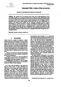
Fig. 1. Link-blockage conditions in MSD-MIMO configuration. a) Side and b) top views of the receiver ( ) and transmitter ( ) mutual positions. The area on the room ceiling that is within the receiver FOV has a radius . and are the height above the communication cell floor and the width of the obstacle. 8 is the emission angle corresponding to the shadowed diffusing spot . and denote the obstacle–transmitter distance. is the receiver–transmitter distance, which equals the communication cell radius when the receiver is placed at the edge of the communication cell. is the height of the communication cell.
R
r
h w DS d d
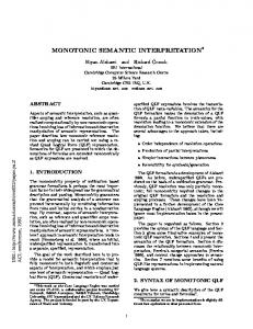
Fig. 2. Circular communications cell formed by 37 diffusing spots. The two patterned circles represent the areas on the ceiling as seen by two receivers that have a FOV of 25 at two randomly chosen positions within the communications cell.
cells. However, when the largest horizontal size of the communication cell is restricted (for example, by considerations about link blockage), a rectangular cell covers a smaller area than the corresponding circular communication cell. In other words, in order to serve a given area, one would need a larger number of base stations forming rectangular communication cell floors as compared to the ones that have circular cell floors, even after allowing for partial overlapping to avoid gaps. A circular communication cell can be conveniently illuminated by diffusing spots on a triangular mesh like the one in Fig. 2. For a typical 3-m-high office, the communication cell radius is 2.1 m and the circular area on the ceiling may be covered by 37 diffusing spots, spaced 70 cm apart. In a room with a larger ceiling height, the communication cell size and the diffusing spots’ lattice spacing are increased correspondingly. However, if the receiver FOV is kept constant, the ceiling area seen by the receiver is enlarged accordingly so that the number of contributing diffusing spots does not change. Therefore, the following analysis about the receiver FOV value is valid for an arbitrary height of the communication cell. III. LINK BLOCKAGE AND RECEIVER FOV In MSD-MIMO, total receiver FOV must be large enough to cover several diffusing spots in order to ensure uninterrupted communications in case some of the diffusing spots are blocked.
H
r
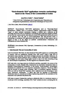
On the other hand, receiver FOV should be as narrow as possible to allow utilization of an optical filter with a narrower spectral bandwidth for better optical noise rejection [11]. We can derive a value for the total receiver FOV (semi-angle of acceptance) from some arguments about system vulnerability to blockage. In the previous section, we have ensured (by restriction of the communication cell size) that the communication link can never be blocked by sitting people. Now, we would like to make link blockage by standing people impossible, as well. By doing this, we aim to design a MSD-MIMO communication system that is robust against blockage. Then, only partial obstruction, i.e., shadowing, would be possible. In the following, we show that our goal can be achieved by restricting the receiver FOV to a value derived from geometrical considerations. Fig. 1 depicts the mutual positions of the receiver and the transmitter; Fig. 1(a) is a side view and Fig. 1(b) is a top view. In is the minimum distance from transmitter (on the Fig. 1(a), line connecting the transmitter and receiver) at which a large obstacle may be placed without blocking all of the transmitter beams that produce diffusing spots within the receiver FOV. depends on the obstacle height . In certain cases, a Also, person standing even closer to the transmitter may not block all transmitter beams. This happens when the blocker lateral dimension and its position are such that some of the transmitter beams can go around and still produce diffusing spots within rein Fig. 1(b) is the minimum transmitter–obceiver FOV. The stacle distance at which not all of the transmitter beams are blocked due to the width of the obstacle. Finally, we may conclude that the obstacle must be at a distance from the transmitter that is larger than that of the shorter one and , in order to prevent blockage of all the beams responsible for transmitting data to a particular user (1) (2) where is the radius of the circle area on the room ceiling seen by the receiver and is the distance between receiver and transmitter. for a receiver positioned at the edge Fig. 3 presents and as functions of the receiver of the communications cell FOV for the case of a typical 3-m-high room. For receiver FOV and are below 50 cm. As we values above 24.5 , both
JIVKOVA et al.: POWER-EFFICIENT MSD MIMO APPROACH
885
Fig. 3. Transmitter–obstacle distance beyond which the obstacle cannot block all the beams responsible for transmitting data to a particular user positioned at depends on the obstacle height and the edge of the communications cell. depends on the obstacle lateral size.
d
d
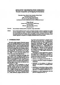
assumed earlier, it is not very likely that an obstacle is within 50 cm from a portable unit or the base station. Therefore, a receiver FOV of 24.5 or more would make the communication system robust against blockage. Actually, this value does not depend on the communication cell height, because and at neither nor depend on . Although any value for the FOV that is larger than 24.5 is good when the link blockage is considered, we should choose the smallest possible FOV value in order to employ an optical filter with narrower spectral bandwidth. Thus, we choose a value of 25 for the receiver FOV in MSD-MIMO links. A receiver having a FOV of 25 encompasses several diffusing spots (Fig. 2). Although there is practically no chance for such a communication link to be blocked, it can be shadowed, i.e., not all but some of the diffusing spots within the receiver FOV can be blocked. The probability and extent of shadowing depend on the spot-array parameters and the particular receiver position with respect to the spot array, as well as on the motion characteristics and the number of people in the office. Since there is no report on the statistics of people motion in offices available in the literature, we assume that it is equally probable that a person is anywhere within the communication cell, except for the close proximity to the portable unit (at a distance shorter than 50 cm, as we explained earlier). There is no analytical function that can describe the effect of shadowing in MSD-MIMO links. Therefore, we applied a statistical approach. For a number of values of the communication cell height , we have simulated the communication link, obtained the channel-impulse response using ray tracing, and computed the reduction (due to shadowing) of the received optical power for 10 000 sets of random receiver and shadowing object positions. Fig. 4 shows that, overall, the probability of shadowing is low and, particularly, that there is less likelihood for link shadowing in rooms with larger ceiling height. IV. TRANSMITTER OPTICS In MSD-MIMO configuration, the optical signal is distributed uniformly within the communication cell. We have proposed a holographic spot-array generator in conjunction
Fig. 4.
Probability of shadowing versus communications cell height
H.
with a single laser source to be utilized at the transmitter in order to create a square array of 10 10 equidistantly positioned diffusing spots of equal power [4]. We could use the same approach to create a triangular mesh of diffusing spots instead of a square one. A computer-generated hologram can be designed to produce any geometrical spot configuration. However, regardless of the particular spot-generator design, the transmitter would utilize a single light source. With such a transmitter, all the time and everywhere within the communication cell, the same data stream would be transmitted. The question “Is this always necessary?” arises. Probably most of the time there will not be users in some parts of the communication cell. Then, the transmitter may provide only the active users with signal and save some power by not distributing optical signal where it is not needed. In other words, a reconfigurable transmitter output is needed. One possible approach to a reconfigurable transmitter is to use multiple light sources, whose output beams are properly shaped and directed. As we have mentioned in the introduction, several separate light sources with individual beam shaping optics have already been used in [6]. The optical system is simple, but this is at the price of bulkiness (which is unacceptable for a portable device) and mechanical complexity (which imposes manufacturing difficulties). Therefore, we prefer utilization of a compact 2-D array of semiconductor light sources. A similar approach has been followed in recent designs of LoS links [7]–[9]. In MSD-MIMO configuration, each light source is responsible for creating a single diffusing spot on the room ceiling, i.e., the number of sources equals the number of diffusing spots needed to cover the communication cell. If there is no need for an optical signal within certain parts of the communication cell, the corresponding light sources are switched off. A VCSEL array is the natural choice for our application. The attractiveness of VCSELs stems from the fact that these laser diodes are very well suited for fabrication in the form of 2-D arrays and are attractive low-cost high-speed sources for free space and fiber coupled links. Relatively high power ( 200 mW) and power-conversion efficiency ( 50%) have been demonstrated [15]. Ga-As VCSELs emitting at 850 nm are already mass produced [15], [16] and longer wavelengths are also available [17].
886
IEEE TRANSACTIONS ON VEHICULAR TECHNOLOGY, VOL. 53, NO. 3, MAY 2004
Fig. 5. Schematic of the proposed transmitter optics. A microlens array collimates the output of the VCSEL array. The role of the deflector is to redirect the laser beams in appropriate directions.
The output beams of the individual lasers in a VCSEL array are parallel to each other and are perpendicular to the plane of the array. The output of each VCSEL from the array is a circular beam with Gaussian profile. Note that in LoS cellular and tracked links it must be flattened in order to uniformly illuminate the corresponding microcell. In MSD-MIMO, such beam flattening is not necessary. Instead, the beam must be collimated, which can be easily performed by a micro-lens array. Also, the output of each element in the laser array has to be redirected (that is, deflected at an appropriate angle) in order to form a particular light spot from the diffusing-spot array (Fig. 5). Since very large deflection angles (up to 45 ) are pursued, a conventional lens system cannot be utilized for this purpose due to the large aberrations at large angles, as is evident from the previously mentioned design solutions for cellular links (see, for example, [8]). Instead, we consider an array of optically recorded volume holograms as a beam-directing element. The holograms must be recorded in a material that is capable of delivering very high diffraction efficiencies, e.g., dichromated gelatin. With optically recorded holograms, it is easy to obtain large deflection angles as long as the recording medium can handle a high spatial frequency. Although in Fig. 5 the collimating and deflecting functions are shown being performed by two separate optical elements, volume holograms can be designed to perform the two functions, simultaneously. With such a transmitter design, independent communication channels (different information streams are launched through different diffusing spots) are feasible, thus providing a means for spatial multiplexing. V. RECEIVER OPTICS Receiver optics have two major functions: concentrating and filtering. These two functions are performed by an optical concentrator in order to increase the received optical signal power and by an optical bandpass filter in order to reject ambient light [Fig. 6(a)]. We have chosen to design receiver optics of the imaging type, similar to the designs in [6] and [12]. The imaging receiver has several important advantages as compared to our previous design of a seven-branch receiver [4], [10]. It is less bulky and can utilize a very large number of detectors, each of which having an optimally small FOV. The imaging receiver comprises an imaging lens system combined with a pixelated photodetector.
Fig. 6. (a) Schematic of custom-designed receiver optics. A lens system focuses the incident light onto a photodetector. An interference filter rejects ambient light. (b) Hexagonal array of 37 photodiodes and the image of a diffusing spot projected onto the array by the receiver lens system.
The small FOV associated with a single detector pixel ensures an optimal ratio between signal and optical noise levels at a receiving element. The major issue when designing an imaging receiver is achieving a large total acceptance angle at a low level of optical aberrations while maintaining a reasonable size of the photodetector array. There are commercially available wide-angle video lenses, but they are not suitable for our application because of the very small entrance aperture. Jungnickel et al. [9] have used such a lens in a LoS tracked system, where a large entrance aperture of the lens is not imperative. The MSD-MIMO configuration is of quasidiffuse type and the optical signal is received after diffuse reflection off the room surfaces so that power efficiency is a major issue in MSD-MIMO links. Larger effective receiver entrance aperture is needed to improve signal reception. We have designed a lens system that ensures a receiver FOV of 25 and has a 3-cm entrance aperture. If the entrance aperture is to be enlarged further, the receiver would become too bulky and the photodetector array would be too large and expensive. Therefore, we have chosen a 3-cm aperture as a reasonable compromise. Djahani and Kahn’s design of an imaging receiver for a MSD-MIMO system [6] also utilizes a 3-cm lens aperture. However, their custom-designed lens system does not seem to exhibit a good image quality because of the very large acceptance semi-angle of 45 , while keeping a reasonable size of the photodetector array. Therefore, the optical signal is spread over a number of detector pixels, thus reducing the signal gain. In our receiver design, lens system images part of the room ceiling onto a hexagonal array of 37 photodiodes, each having a 2.8-mm side. The photodiode array covers a circular image area with diameter of 28.2 mm, completely [Fig. 6(b)]. For a 10-cm diffusing spot approximately 2 m away from the receiver, the size of the diffusing spot image is between 1.7 and 2.48 mm, depending on the angle of arrival. In all cases, it is smaller or equal to the side of a hexagonal pixel in the photodiode array. This implies that practically no more than three pixels can be partially overlapped by a diffusing spot. This is shown in Fig. 6(b). An interference filter of narrow spectral bandwidth is employed to reduce the optical noise from artificial and natural light sources. The minimum value of spectral bandwidth
JIVKOVA et al.: POWER-EFFICIENT MSD MIMO APPROACH
887
depends on the maximum angle of signal reception, i.e., on the receiver FOV
where is the signal wavelength and is the effective refractive index of the optical filter [18]. Thus, the narrower the receiver FOV, the smaller the filter spectral bandwidth and the better the optical noise rejection. At the spectral interval of in) and for a FOV of 25 , a value of as terest (850 nm–1 small as 25 nm is possible. VI. POWER REQUIREMENTS In MSD-MIMO links, several virtually ideal communication channels are established between the base station and a user terminal. When an imaging receiver like the one described in the previous section is employed, the number of ideal channels equals the number of photodetector pixels that receive optical signal. The output electrical signals from all active pixels are amplified separately and then processed according to some selection-combining technique. We consider two ways of combining the electrical signals: select combining (SC), which is the simplest to implement, and maximal ratio combining (MRC), which gives the best results. In SC, the receiver pixel with the highest SNR is selected. In MRC, the signals are combined using weights that are proportional to the individual SNRs perceived by the active pixels so that the output SNR is the sum of these individual ratios (see, for example, [19]). When employing a multisource transmitter, the total transmit power depends on the number of diffusing spots that appear within the combined FOVs of all active users, i.e., on the number of the VCSELs in the laser array that are on. Thus, the required average transmit power of a single VCSEL may be used as a proper measure of the system power efficiency. A relatively omnidirectional background high level of light is assumed for the computations. This is approximately the value of background spectral radiance of diffuse sky in the spectral range of interest [1], which is the worst-case scenario. In Fig. 7, the average transmit power is shown for the cases of SC and MRC diversity-combining techniques when the simplest modulation scheme with no equalization at the receiver, namely OOK with NRZ format, is used. Numerical computations use the analysis presented in [19]. A large number (10 000) of receiver positions have been randomly chosen and the corresponding communications links have been simulated for each in order to obtain statistical results for the system performance. As expected, MRC combining results in about 4 dB power saving as compared to SC. As we have shown earlier [20], system power efficiency may be further improved with the use of power efficient signaling schemes such as -level pulse-position modulation (L-PPM). Power-efficient schemes are usually bandwidth inefficient and lose their effectiveness in lowering the power requirements over band-limited communication channels as the data rate is increased. The band-limited behavior of the channel is due to multipath dispersion, which creates intersymbol interference (ISI) when signals at high data rates are transmitted over the channel.
Fig. 7. Required average transmit power of a single laser in the transmitter laser array for OOK modulation with SC or MRC combining for a bit-error rate of 10 . Note that the required average transmit power is given in dBm, which is 10 log (P ) where P is the required power in milliwatts.
Fig. 8. Required average transmit power of a single laser in the transmitter laser array for OOK or L-PPM modulation with MRC combining for a bit-error rate of 10 . Note that the required average transmit power is given in dBm, that is, 10 log (P ), where P is the required power in milliwatts.
For example, at high data rates, ISI can bring the power requirements of L-PPM to a level exceeding that of a simple OOK system [21]. Fortunately, this is not the case in MSD-MIMO links; we have shown that these links are virtually free from multipath dispersion and exhibit a 3-dB bandwidth of the order of a few GHz [10], [20]. Then, an L-PPM modulation scheme may be utilized to significantly lower the required average transmit power. The details of how to apply L-level pulse-position modulation in MSD-MIMO links can be found in [20]. As can be seen from Fig. 8, when 16 PPM is used, power savings of more than 7 dB, as compared to OOK, may be obtained. VII. EFFECT OF LINK SHADOWING ON REQUIRED TRANSMIT POWER We have shown in Sections II and III that MSD-MIMO links can be designed to be robust against blockage by people of average height. Thus, complete interruption of the data transfer is not very likely to occur. However, possible shadowing may reduce received signal power and cause erroneous reception of
888
IEEE TRANSACTIONS ON VEHICULAR TECHNOLOGY, VOL. 53, NO. 3, MAY 2004
Fig. 9. Probability distribution of power reduction due to shadowing.
symbols. The effect of shadowing on link quality can be alleviated either by using appropriate coding schemes or by increasing the transmit power. According to the simulations results shown in Fig. 4, in a typical 3-m-high room, in only about 1.9% of the cases, there is some shadowing. Further, by analyzing the received power in 10 000 cases of random receiver and shadowing object positions, we have obtained the probability distribution for certain reduction in the received signal power caused by shadowing. It is shown in Fig. 9, in a majority of the shadowed cases, that the shadowing causes less than a 50% reduction in the received power. Therefore, the power penalty due to shadowing is insignificant. For instance, in the case of OOK with MRC it is less than 0.1 dB in 99% of the cases (1% outage). VIII. CONCLUSION A vital factor that affects the quality of service in indoor optical wireless communication systems is their vulnerability to shadowing and blockage. An opaque object can partially shadow or completely block an optical link, because infrared light does not penetrated opaque barriers. Based on considerations about blockage caused by sitting people, we have concluded that the maximum radiation angle at the transmitter should not exceed 45 , which restricts the communication cell size. In this case, MSD-MIMO links are robust against blockage, although still vulnerable to shadowing. However, in a typical office having a height of 3 m, the probability of shadowing caused by standing people is less than 2% and, in the majority of the shadowed cases, the shadowing causes less than 50% reduction in the received signal power. The power penalty due to shadowing is insignificant (less than 0.1 dB in 99% of the cases). MSD-MIMO links are virtually free from multipath dispersion; therefore, they have great potentials for high-speed communications. Yet a major issue is the poor power efficiency that is characteristic to all nonline-of-sight links. We propose a reconfigurable transceiver design that reduces the required transmit power. This is achieved by introducing multiple light sources at the transmitter that can be turned on and off independently, according to the instantaneous needs, thus creating independent communication channels, and by using an imaging receiver with a pixelated photodetector for direction
diversity detection. The optimal receiver FOV is deduced by considerations about link blockage and optical noise reception. In MSD-MIMO configurations, a user terminal communicates with the base station through several communication channels with uncorrelated noise. This allows for a maximum-ratiocombining technique to be employed, so that the output SNR is significantly increased and power requirements are lowered accordingly. Virtually unlimited channel bandwidth in MSD-MIMO links allows for power efficient signaling schemes such as L-PPM to be utilized. This brings the required average transmit power down to approximately 0 dBm per laser source in the transmitter VCSEL array at 200 Mb/s, even after considering a link power budget margin of approximately 2 dB. REFERENCES [1] J. R. Barry, Wireless Infrared Communications. Boston, MA: Kluwer, 1994. [2] Safety of Laser Products—Part 1: Equipment, Classification, Requirements and User’s Guide, IEC 825-1 Int. Standard, 1993. [3] G. Yun and M. Kavehrad, “Spot diffusing and fly-eye receivers for indoor infrared wireless communications,” in Proc. IEEE Int. Conf. Selected Topics in Wireless Communications, Vancouver, BC, Canada, 1992, pp. 262–265. [4] M. Kavehrad and S. Jivkova, “Indoor broadband optical wireless communications: Optical subsystems designs and their impact on the channel characteristics,” IEEE Wireless Commun., vol. 10, pp. 30–35, Apr. 2003. [5] M. R. Pakravan, E. Simova, and M. Kavehrad, “Holographic diffusers for indoor infrared communication systems,” in Proc. IEEE Global Telecommunications Conf. (GLOBECOM’96), vol. 3, 1996, pp. 1608–1612. [6] P. Djahani and J. M. Kahn, “Analysis of infrared wireless links employing multi-beam transmitters and imaging diversity receivers,” IEEE Trans. Commun., vol. 48, pp. 2077–2088, Dec. 2000. [7] J. Bellon, M. J. N. Sibley, D. R. Wisely, and S. D. Greaves, “HUB architecture for infrared wireless networks in office environments,” Proc. Inst. Elect. Eng. Optoelectron., vol. 146, no. 2, pp. 78–82, 1999. [8] F. Parand, G. Faulkner, D. O’Brien, and D. Edwards, “A cellular optical wireless system demonstrator,” in Inst. Elect. Eng. Colloq. Optical Wireless Communications (Ref. 1999/128), 1999, pp. 12/1–12/6. [9] V. Jungnickel, A. Forck, T. Haustein, U. Krueger, V. Pohl, and C. von Helmolt, “Electronic tracking for wireless infrared communications,” IEEE Trans. Wireless Commun., vol. 2, pp. 2145–2153, May 2001. [10] S. Jivkova and M. Kavehrad, “Receiver designs and channel characterization for multi-spot high bit rate wireless infrared communications,” IEEE Trans. Commun., vol. 49, pp. 2145–2153, June 2001. [11] K. H. Po and J. M. Kahn, “Compound parabolic concentrators for narrowband wireless infrared receivers,” Opt. Eng., vol. 34, no. 5, pp. 1385–1395, 1995. [12] D. O’Brien, G. Faulkner, K. Jim, E. Zyambo, D. Edwards, M. Whitehead, P. Stavrinou, G. Parry, J. Bellon, M. Sibley, V. Latithambika, V. Joyner, R. Samsudin, D. Holburn, and R. Mears, “High-speed integrated transceivers for optical wireless,” IEEE Commun. Mag., vol. 41, pp. 989–999, Mar. 2003. [13] A. Sato, T. Ohtsuki, and I. Sasase, “Effects of shadowing on nondirected LOS indoor infrared wireless systems with site diversity,” in Proc. IEEE VTC’00, 2000, pp. 1550–1554. [14] A. M. Street, K. Samaras, D. C. O’Brien, and D. J. Edwards, “High speed wireless IR-LANs using spatial addressing,” in Proc. Eighth Int. Symp. Personal, Indoor and Mobile Radio Communications (PIMRC’97), vol. 3, Finland, 1997, pp. 969–973. [15] K. Iga, “Semiconductor laser in the 21st century,” in Proc. SPIE, vol. 4286, 2001. [16] S. Hunziker, S. Eitel, K. Gulden, M. Moser, R. Hoevel, H. P. Gauggel, and M. Brunner, “VCSEL arrays,” in Proc. SPIE, vol. 4286, 2001, pp. 203–209. [17] C. Chang-Hasnain, “Progress and prospects of long-wavelength VCSELs,” IEEE Commun. Mag., vol. 41, pp. 64–68, Feb. 2003. [18] H. Macleod, Thin-Film Optical Filters. New York: Adam Hilger, 1986.
JIVKOVA et al.: POWER-EFFICIENT MSD MIMO APPROACH
[19] W. Jeong, M. Kavehrad, and S. Jivkova, “Broadband infrared access with a multi-spot diffusing configuration: performance,” Int. J. Wireless Inform. Networks, vol. 8, no. 1, pp. 27–36, 2001. [20] K. Akhavan, M. Kavehrad, and S. Jivkova, “High-speed power-efficient indoor wireless infrared communication using code combining—Part I,” IEEE Trans. Commun., vol. 50, pp. 1098–1109, July 2002. [21] M. D. Audeh, J. M. Kahn, and J. R. Barry, “Performance of pulse-position modulation on measured nondirected indoor infrared channels,” IEEE Trans. Commun., vol. 44, pp. 654–659, June 1996.
Svetla Jivkova received the Ph.D. degree in physics from the Bulgarian Academy of Sciences, Sofia, and the M.S. degree in physics with a specialization in optics in 1985 from the University of Sofia, Sofa, Bulgaria. She was an Assistant Professor in the Electrical Engineering Department, The Pennsylvania State University (Penn State), State College, and a Research Associate with the Center for Information and Communications Technology Research (CICTR), Penn State. Currently, she is with the Central Laboratory of Optical Storage and Processing of Information, Bulgarian Academy of Sciences. She has published a large number of papers in the most prestigious international journals in optics, which are widely cited by other researchers in these fields. She has contributed to the Communications and Signal Processing area of the Electrical Engineering Department both in conducting research and teaching. Her former research experience includes holographic storage of information, dynamic holography with photorefractive crystals, and optical processing of information. At Penn State, her research was centered on optical wireless communications, optical systems design, and holography. While with Penn State, her research interests expanded into other work areas, namely, optical wireless communications, computer-generated holography, holographic optical elements design, and photonic band-gap structures. Many prestigious news articles, including an August 23, 2001 article in The New York Times by David F. Gallagher entitled, Beaming Data Holds Promise, With Limits, for Networking, have acknowledged her contributions to the communications field. Her research interests include holography, photorefractive crystals, interferometry, optical processing of information, and coherent amplification of optical signals.
889
B. A. Hristov, photograph and biography not available at the time of publication.
Mohsen Kavehrad (S’75–M’78–SM’86–F’92) received the Ph.D. degree from the Polytechnic University (Brooklyn Polytechnic), Brooklyn, New York, in electrical engineering in 1977. He was with the Space Communications Division, Fairchild Industries and the satellite corporation and laboratories, GTE, from 1978 to 1981. In December 1981, he joined Bell Laboratories. In March 1989, he joined the Department of Electrical Engineering, University of Ottawa, as a Full Professor, where he also was Director of the Broadband Communications Research Laboratory. He also was the Director of Photonic Networks and Systems Thrust and a Project Leader in Communications and Information Technology Ontario (CITO) and the Director of the Ottawa-Carleton Communications Center for Research (OCCCR). In January 1997, he joined the Department of Electrical Engineering, The Pennsylvania State University, State College, as the AMERITECH (W. L. Weiss) Professor of Electrical Engineering and the Director of Communications Engineering. Later, in August 1997, he was appointed as the Founding Director of the Center for Information and Communications Technology Research (CICTR). From 1997 to 1998, he also was the CTO and a Vice President at Tele-Beam, Inc., State College, PA. His work has been published in over 270 refereed journals and conference papers, several book chapters, and books. He holds several key issued patents in these areas. His research interests are in the areas of technologies, systems, and network architectures that enable the vision of the information age; e.g., broad-band wireless communications systems and networks and optical fiber communications systems and networks. He was elected a Fellow of the IEEE in January 1992 for his contributions to digital wireless communications and optical fiber systems and networks. He has received three Exceptional Technical Contributions awards while he was with Bell Laboratories for his work on wireless communications systems. He also received the 1990 TRIO Feedback award for his patent on a Passive Optical Interconnect and the 2001 IEEE VTS Neal Shepherd Best Propagation Paper award and three IEEE Lasers and Electro-Optics Society Best Paper awards, as well as a Canada NSERC Ph.D. dissertation award, jointly with his former graduate students for their work on wireless and optical systems. He has lectured worldwide as an IEEE Distinguished Lecturer and as plenary and keynote speaker at leading conferences.