2005 International Conference on Wireless Networks, Communications and Mobile Computing
Power-Efficient Routing (PER) Mechanism for ODMA Systems Ray-Guang Cheng+, Shin-Ming Cheng++, and Phone Lin++
+Dept. of Electronic Eng., National Taiwan University of Science and Technology, Taipei, Taiwan Dept. of Computer Science and Information Eng., National Taiwan University, Taipei, Taiwan
crg(d!ieee.org,
[email protected], plinacsie.ntu.edu.twv Abstract
This work presents a power-efficient routing (PER) mechanism to identify a minimum-power path for the Opportunity Driven Multiple Access (ODMA) communication in UMTS system. Prior to the route discovery, the PER mechanism utilizes an analytical solution to predict the total power and number of intermediate UEs required in the minimum-power path. With the prediction, the PER mechanism provides a method to set the transmission power and maximum hopcount such that the power consumption of each UE during the route discovery is significantly reduced. Simulation results demonstrate the accuracy of the prediction and the required signaling of PER is dramatically reduced compared to dynamic source routing (DSR).
1. Introduction In a wireless communications system, the majority of transmission power is used to overcome radio propagation loss. To save power, it is beneficial to break a long path into a number of short links [1-3], and to relay data through these short links. In the Universal Mobile Telecommunications System (UMTS) [1], a cellular multihop method called Opportunity Driven Multiple Access (ODMA) has been proposed to reduce power required for transmission from mobile stations (also known as User Equipments (UEs) in UMTS), extend the coverage area of the base station (called Node B in UMTS), and increase the data transfer rate of users. User data in ODMA are exchanged between a sending UE and Node B by being relayed through intermediate UEs. Although there are advantages to ODMA, there are extra costs. The sending UE should establish a routing path through the intermediate UEs to Node B prior to data exchange. Moreover, each intermediate UE needs extra power to relay the data. Hence, the total power required for the ODMA communication depends on the way to identify intermediate UEs. Thus, power-efficient routing is a key issue for ODMA. The functions of ODMA closely resemble those of mobile ad-hoc networks (MANET) [4]. However, they differ mainly in that Node B is located in a well-known fixed position in ODMA; however, both communication parties are mobile in MANET. Several power-aware routing methods [5-10] have been proposed for MANET and ODMA cellular networks. Most of the proposed methods are developed out of dynamic source routing (DSR) 'With DRX, a UE is in sleep mode most of the time to save power and
periodically wakes up to gather system information. The UE may not try to collect information from other UEs as all information would be obsolete after returning to sleep mode.
0-7803-9305-8/05/$20.00 ©2005 IEEE
129
protocol [11] and ad-hoc on-demand distance-vector (AODV) routing protocol [12]. In DSR and AODV, the source node initiates a route discovery procedure by flooding a route request (RREQ) packet to its surrounding nodes. The RREQ is always forwarded by intermediate nodes until the destination node is reached. The destination node sends back a route reply (RREP) packet carrying the power metrics of the selected path(s) to the source node. A minimum-power path is then identified based on the collected metrics. The power consumption of nodes in MANET were first considered by Singh, Woo, and Mghavendra [5] in designing their routing method. Chang and Tassiulas [7] investigated the residual power of UEs in designing their energy-efficient routing algorithm. Rodoplu and Meng [8] proposed a position-based routing method for mobile wireless networks. This method constructed a position-based sparse graph for all communication links connecting mobile nodes and then derived a minimumpower routing topology from the graph. Wattenhofer, et. al. [9] proposed a distributed topology-control algorithm for MANET. In adopting directional antenna technology, each UE constructed a communication graph, removed the nonefficient edges from the graph, and derived a minimumpower routing topology. Vodafone Group [10] proposed an ODMA routing procedure in which the given local and endto-end connectivity information was utilized to construct the routing path. Two significant assumptions are made in these approaches. The first assumption is that each node retains the up-to-date location information and/or power metrics of the other nodes. This assumption may be effective in MANET but is not suitable for mobile cellular networks: each UE in a mobile cellular network does not have up-todate information of other UEs due to the DRX' function. This assumption can be relieved by employing reactiverouting approaches [13]. However, existing reactive-routing approaches can only obtain the information of other UEs after executing route discovery; hence, some routing control messages are wasted on processing non-attainable ODMA requests (i.e., those requests whose power or latency requirements cannot be attained by utilizing the ODMA technology). The second assumption is that the extra power used by RREQ signaling is ignored; therefore, RREQ in MANET is always flooded among UEs with the UE's maximum transmission power and without hop-count limitation. However, the UE's transmission power can be up to several Watts in a mobile cellular network and thus, cannot be neglected.
This work presents a power-efficient routing (PER) mechanism to identify a minimum-power path for the ODMA communication. Different to existing reactiverouting approaches, the PER mechanism utilizes an analytical solution to predict the total power and number of intermediate UEs required in the minimum-power path prior to the route discovery. With the prediction, route discovery procedures originated from non-attainable ODMA requests can be prevented. For those attainable ODMA requests that require a route discovery procedure to locate intermediate UEs, the PER mechanism further provides a method to set the transmission power and maximum hop-count when forwarding RREQ. With the setting, the power consumption of each UE during the route discovery is significantly reduced. The rest of this paper is organized as follows. The proposed PER mechanism is described in Section 2, and its key parameters and their effects on the system performance are discussed. Section 3 presents an investigation of the proposed PER mechanism's performance via numerical analysis and simulation. Conclusions are finally drawn in Section 4.
2. PER Mechanism An ODMA network comprises a Node B and several ODMA-enabled UEs, which are identified by their userspecific identities (ODMA_IDs). To simplify this presentation, from this point forward the term UE will only denote an ODMA-enable UE. In an ODMA transmission, the role of UEs can be categorized as three types: SendingUE, BackerUE, and RelayUE. A SendingUE is the UE that originates the ODMA transmission. The other TEs that participate in the ODMA communication within the cell are known as BackerUEs. Among these BackerUEs, some will be identified as RelayUEs, which are responsible for relaying data packets between the SendingUE and Node B. Note that UEs that do not have sufficient residual-power may optionally disable some ODMA functionalities to minimize unnecessary power consumption. Three power-consumption modes of the UE are considered herein: sleep (SLP), receiving (RX), and transmitting (TX). The UE consumes the least amount of power while in SLP mode, during which only a timer is activated. In RX mode, the receiver is turned on and thus, the UE can receive data from other UEs and Node B. In TX mode, the transmitter is turned on and the UE can adjust its transmission power to transmit data. Details of the PER mechanism are described as follows. Before going into details, the PER mechanism's parameters are defined. Pref and aIPref are the minimum and maximum power consumed by the UE in TX mode; IPref is the average power consumed by the UE in RX mode; yPIe is the average power consumed by the UE in SLP mode; and, a, /B, and y are constants, where a > 1>> , > Y > 0
[2].
130
PT _P is the transmission power used by UE when forwarding RREQ in the path discovery phase. * N. is the maximum hop-count that an RREQ can traverse in the path discovery phase, and N0p, is the number of RelayUEs required by an optimal path. Note that the optimal path is identified only under perfect conditions (i.e., it can find RelayUEs at any location within a cell). * PO, is the total power required by the i-th path discovered in the path discovery phase, and POP, is the total power required by the optimal path. Note that Polal,j Popt * P,, is the transmission power used by the SendingUE to send the ODMA service request. The PER mechanism consists of three phases: access phase, path discovery phase, and path setup phase. In access phase, the SendingUE adjusts its transmission power to PI,,, and sends an ODMA service request carrying Pf to Node B. Node B can predict Po, and N0p from Pk By using these predicted POP, and Nop,, Node B can check whether the ODMA request is attainable or not. For nonattainable ODMA requests, Node B simply terminates the PER procedure by replying the SendingUE with a rejection message. For attainable ODMA requests, Node B further derives PT R_D)P and N , and sends a confirmation message carrying PT _PD and N. to the SendingUE. In path discovery phase, similar to DSR [11], the SendingUE broadcasts an RREQ through the i-th paths to the Node B to collect P1oiaIJ In this phase, each BackerUE floods the RREQ with transmission power PT RDP and discards the RREQ that exceeds the hop-count limitation N.. Based on the collected PJThal,, Node B can identify the minimumpower path. As an optional, Node B may still refuse the ODMA request if min P,, i >> P1, , . In path setup phase, Node B sends an RREP packet back to the RelayUEs along the identified path. The proposed PER differs from DSR in the following respects. First, PER can predict P; before the route discovery. Second, the hop-count limitation for RREQ is infinite in DSR but is N.,a in PER. Third, the transmission power utilized to forward the RREQ is aPref in DSR but is PT RDP in PER. The derivation of PT PDP Niiiax , and Pini is next elucidated. *
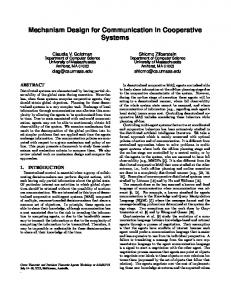
First investigate Pto,i, by considering a co-linear network topology (Fig. 1), in which Node B, N RelayUEs, and the SendingUE (i.e. UE1) are located along a line. For sake of simplicity, RelayUEs are numbered in order and denoted as UEj, where j=2,..., N+ 1. Let the distance
between the SendingUE and Node B be d. Assume that the UE density in a cell is sufficiently high such that an UE can be found at any location along the line. The distance between UEj and UEj1 is a continuous random variable di. The UEs are operating in TX and RX modes during an ODMA communication. In TX mode, the transmission power required by an UE depends on the radio channel condition. Typically, the radio channel condition is characterized by a large-scale propagation model2 and a small-scale propagation model3 [14]. Rodoplu and Meng [8] proved that a minimum-power network design that addresses the increase in transmission power when handling large-scale variations is fundamentally the same design as that which considers only the path loss. Hence, a path-loss model with the following characteristics is employed: a power-law attenuation factor n [14]; antenna gain of an UE's transmitter (receiver) G, (Gr); and, the system-loss factor L (L . 1). The following Lemma is first presented. . For a given N, the lower bound of the power required by the path to Node B, denoted as P, is obtained by k
=min P {o Pm (N.
N
for N > P- d-1,
d'
power required by the UE to correctly decode a message. Note that Pd can be properly set by considering effects of shadowing and fast fading. The total power required by the optimal path, denoted by POP, is attained when N = Nop,
That is,
Ppt = Pt IN=N_, n~ d-i-d~
where if
(n
dflP>
relf [
ref
d-i
kdn n-
otherwise.
Due to the space limitation, the derivation of Lemma 1 is not presented herein. A similar result of Lemma I is also obtained in [15]. Lemma I proves that J and P1, depends on following parameters: UE capabilities (i.e., fi, Pref, Pd ); the path loss exponent (i.e., n); the distance between a source UE and the Node B (i.e., d); and, the number of RelayUEs (i.e., N). Among these parameters, the only unknown factor is d. In mobile cellular networks, the UE normally utilizes an openloop power control mechanism [14] to estimate d. Let PBCH and Pamg be the BCH power transmitted by Node B and the 2
kPavs d
4 dN
dA+l Node B
UEN+1
UiEN
UE2
dII
UE,
Figure 1. A co-linear network topology consisting ofN+2 coliner nodes, UE1,..., UEN+j and Node B. Hence, the initial transmission power used by the SendingUE to send the ODMA service request to the Node B, Pi.i, is given by
1PBCH p avg
re
where k = (4X)2 L p . A is the wavelength, and Pd is the
GIGrA2
d = PBCH
I
+N/NPref, for O< N < k,
I(N + I + N,/)Pref,
power received by the SendingUE, respectively. In UMTS, PBCH is a constant and is periodically broadcasted by Node B. Hence, the SendingUE can estimate d based on the path loss model, that is,
A large-scale propagation model is utilized to predict the mean signal power for a relatively long transmitter- receiver separation. The path loss and the shadowing effect are considered. 3Small-scale propagation model characterizes the rapid fluctuations of the received signal strength over a very short distance. Delay spread due tj 31 multi-path and Doppler effects are considered.
Lemma I suggests that, with Nm = N0p, +1 and PT RDP = PO, an optimal path in a co-linear network topology is obtained given sufficiently high UE-density. For low UIE-density, the optimal path may not be found. To solve this problem, a RelayUE can increase PT R.DP and find another RelayUE in its neighborhood. Therefore, under a general condition where UEs density could be low and UEs are not located along a line, the minimum-power path can still be obtained if Nmax = NPt +1 and PT -RDP = po (i.e., aPIef / Po 8 a > 1 ) is used. Note that, under this the total power required by the minimum-power condition, path is higher than Popt . The RelayUEs may be located in the vicinity between the SendingUE and Node B. As demonstrated in Fig. 2, BackerUEs located in the region where the two circles overlap (both circles have the same radius P.I and are centered at Node B and the SendingUE) could be possible RelayUE candidates. Hence, in PER, only these BackerUEs, rather than all BackerUEs in the entire cell, should forward RREQ during route discovery. These BackerUEs can be identified easily because they can receive the ODMA service request and confirmation from the SendingUE and Node B. Figures 2 and 3 show a general network topology and the message flows employed to demonstrate a scenario of the PER mechanism, respectively. In this scenario, UE, is the SendingUE; UEj, for j=2,...,12, are BackerUEs; and, N.Pt = 1 is assumed. As shown in Fig. 2, UE1I cannot receive the ODMA service request from UE1 and UE12
cannot receive the confirmation from Node B; hence, UEII and UE12 automatically enter SLP mode after timeout. The RREQ message traversing along UE1-UE6-UE7 is discarded by UE7 because Nnax is reached. Without otherwise specified, messages are carried through the logical channels specified in parenthesis in Fig. 3 (i.e., ORACH denotes the ODMA random access channel [1]). The three phases of the PER mechanism are described as follows.
Step 1. Prior to communicating with SendingUE UE1 measures P transmission power to Pinit, and RRC Connection Req [1] carrying
Node B, the , adjusts its then sends an PJn to Node B.
Step 6. Node B sends an RRC Connection Setup [1] to UE7carrying the ODMA traffic channel (ODTCH) and ODMA control channel (ODCCH) allocation [1]. The remaining BackerUEs whose ODMA_ID are not on the RoutingList move to SLP mode. Step 7. The ODMA communication path is established. The established communication path may be broken by the movement of UEs. As an optional, Node B may repeat Steps 5 to 7 to create one or more backup communication paths for the SendingUE.
Step 2. Upon receiving the RRC Connection Req message, Node B adjusts its transmission power to Pi, and acknowledges an ODMA Relay Prepare carrying PT _RDP and Nmax to UE1.
In the path discovery phase, the SendingUE adjusts its transmission power to PT RDP and floods an RREQ (i.e., ODMA Relay Req) to surrounding BackerUEs. The RREQ carries three parameters: SID, RoutingList, and Pacc,j. The SID is the ODMA_ID of the SendingUE utilized to identify a specific ODMA connection request; the RoutingList contains ODMA_IDs of UEs that comprise the specific path; and, the PaCC1 is the accumulated power required for the path from SendingUE to UE,. Step 3a. UE1 sends an ODAM Relay Req carying (SID= 1, RoutingList-NULL, Pacc,,=O) to its neighboring UEs and UE7 updates the accumulated power by P
-P
acc,7 -
acc,I
+P
T ,I
Pcc,7
+ PT 7
Access Phase
:t
Pacc,7 + max(PT
(ORACi)
Note that the power used by Node B's receiver is not considered. Step 3b. UE6 receives the RREQ from UE1, updates the triplet, and forwards the RREQ to UE7. Step 4b. UE7 discards the RREQ because NA/ax is reached.
Step 5. Node B determines the minimum-power path, which has the least Pacc,toiai among all discovered paths, and identifies UE7 as the RelayUE from the RoutingList.
*
ra
vrbrs
§\~ ~ ~ ~ ~ ~-
3a. ODMA_Relay_Req (ORACH)
Path
4a. ODMA_Rebay_Rec (ORACH)
Discovery Phase
Path Setup
Phase
|3ODMA_Relay_Rec (ORACH)
4b. ODMA_Relay_Req (ORACH)
requests
PR,NodeB Pref
UE,
2. ODMA_RelayPrepare (ORACH)
Discard invalid
_RDP
I
UE,
L
R ,7
Step 4a. UE7 forwards the RREQ carrying (SID=1, RoutingList-=7, P,cc,7) to Node B. Node B updates the total accumulated power PaCCiotat of this path by =
v
Node B UE, 1. RRCItConnection_Req
+P
=accP, + max(PT _RDP IPR7,IPref ) + /Pref .
Pacc,total
Figure 2. A network topology illustrates the PER mechanism.
(
5.Determine the minimum,eegypt 6. RRC_Connection_.Setup (ORACH) 7. RRCQ_Connection_Setup (ORACH)
Figure 3. Message flow of the PER mechanism.
3. Numerical Results Simulations were conducted to verify the effectiveness of the proposed PER mechanism. A discrete simulation model, which is similar to the one used in [16], was developed to validate the accuracy of the analysis. The load balancing capability of ODMA was not investigated herein. Hence, a single cell with 250 to 2,500 UJEs was considered. All UEs were assumed to be uniformly distributed within a square area with dimensions 5kmx5km. The constants used herein are listed as follows:f= 1900 MHz, Gt= G,- 1, ko= 6334, a = 20, , 0.1,...,0.9, n = 2, P = 20 mW, Pd 10-8mW, d= 2100 m, and 3:= 1.5. Each sample during the =
132
simulation was obtained by averaging the outcomes from 106 identical experiments. Both DSR and PER were simulated. The DSR was chosen as a benchmark because it can explore all paths and identify the minimum-power path in a cell. In the simulation, both DSR and PER found the same minimum-power path, but with different signaling overhead. Hence, the optimum route discovered by DSR was not specifically identified in Figs. 4 and 5. In Figs. 4 and 5, numerical results are denoted with lines, while simulation results are presented with symbols. The accuracy of the analysis was first verified by simulation. In Fig. 4, the total power required by the path (i.e., P ) for various UE densities and number of RelayUEs (i.e., N ) were shown, in which /3= 0.5 was assumed. Lemma I obtained N0,1 3 and Pw = 100 mW. Note that for d = 2100 m, the SendingUE required 279 mW to transmit data directly to Node B without using ODMA. Simulation results showed estimation errors for low UEdensities (Fig. 4). However, the estimation error was considerably reduced when UE-density was larger than 5x10⁻⁵ UEs/m2. This finding was a result of the high UEdensity assumption in Lemma 1. For low UE-density, the RelayUEs could not be found at expected locations and, therefore, the lower bound was not achieved.
150
-=
= =
=
N meant to add new RelayUEs in the path. Since these new RelayUEs consume extra power, it is not valuable to reduce I, by increasing the number of RelayUEs unlimitedly, particularly for those RelayUEs that have high /3. In other words, using RelayUEs closer than I I(N0 , + 1) together results in greater overall energy use, since the savings in TX power from using smaller hops is lost given that nothing less than Pref can be used. Lemma I proved that the minimum P was obtained if N0P, RelayUEs were utilized in a path. For N Nop, reducing the distance between two adjacent RelayUEs did not further reduce the transmission power of each RelayUE because the transmission power was bounded by Pref; therefore, P, was monotonically increased.
t
145 140-
-4-
-*--
----
*
4-
§~135
-4--
0- N=1:
N= 1
Om 130 -
125 120
-+ -
-
-
E Q:L
Simrulation
Analytical
N=2: Simulation N=2: Analyfical N=3: Simulation N=3: Analytical N=4: Simulation N=4 Analytical
115 1
2
3
4
5
UE-density (Unit:
6
7
105 UEsIm2)
8
9
N
10
Figure 5. Total power required by the path for various N and /3.
Figure 4. Total power required by the path for various UE densities and N.
In the following two examples, UE density is fixed to 5x10⁻⁵ UEs/m2. Figure 5 showed the P for various N and /3. From Lemma 1, it can be derived that N =2 for ,= 0.7 and 8 = 0.9; andN0> = 3 for / = 0. 1, /3= 0.3, and /3=0.5 ; each derived N1 coincided with the simulation results shown in Fig. 5. Figure 5 demonstrated that for a fixed N, decreased f/ resulted in a lowered P, since a low power is required by the receiver of each RelayUE. For a given /3, P was first decreased and then increased when N was increased from I to 6. The rationale for the variation of P, is described as follows. Increasing
133
As mentioned earlier, both DSR and PER were able to locate the same minimum-power path; however, their signal costs were substantially different. In DSR, the UEs floods the RREQ over the entire cell with transmission power aP,ef. However, in PER, only selected BackerUEs flood the RREQ with transmission power 5P3. Figure 6 showed the signaling cost of DSR and PER. The number of RREQs, (i.e., denoted as NS,1g ) and the total power consumed by the RREQs (i.e., denoted as Ps,ga) were investigated and were illustrated in Figs. 6(a) and 6(b), respectively. In this example, 3= aPeu/f PO and 3 = 1.5 were used in PER1 and PER2, respectively. The proposed PER mechanism
dramatically reduced Nsi . For a =aPre the P /a transmission power utilized by PER1 was the same as that employed by DSR. However, Nsgllal of PER1 was significantly reduced than that of DSR because, in PER, fewer BackerUEs were allowed to forward the RREQ. Simulation results of PER, and PER2 also demonstrated that a small a results in a small Ns5ij1 However, reducing Ns,gnl, by lowering a increased the risk of locating no path during the route discovery, particularly for those networks with low UE density. Since the optimization of a is not essential for the effectiveness of the PER mechanism, it's optimization will be the subject of future work.
-ii M
z'
4. Conclusion (a) Total number of RREQ messages.
This work presents a PER mechanism for ODMA cellular networks. In contrast to previous routing approaches, the proposed PER mechanism accurately predicts the power consumption of, and the number of relay nodes for, an optimal path without information from the other nodes. Based on its prediction, Node B accepts the ODMA communication if the power and latency requirements of the requested UE are guaranteed. The effectiveness of the proposed mechanism is shown both theoretically and via simulation. Simulation results demonstrate that with carefully chosen parameters, the PER mechanism can identify the minimum-power path with relatively low signaling cost compared to that of DSR.
i4-
.0 2-
5. References
-O
[1] 3GPP, "Opportunity driven multiple access," 3G TR 25.924, v. 1.0.0, Dec. 1999. [21 H. Karl (Editor), "An overview of energy-efficiency techniques for mobile communication systems," Report of AG Mobikom WG7, Oct. 2003. [3] C. E. Jones, K. M. Sivalingam, P. Agrawal, and J. C. Chen, "A survey of energy efficient network protocols for wireless networks," Wireless Networks, vol. 7, pp. 343-358, 2001. [4] A. J. Goldsmith and S. B. Wicker, "Design challenges for energy-constrained ad hoc wireless networks," IEEE Wireless Comm., vol. 9, no. 4, pp. 8-27, 2002.
[51 S. Singh, M. Woo, and C.S. Mghavendra, "Power-aware routing in mobile ad hoc networks, ACM/IEEE MobiCOM, pp. 181-190, 1998. [6] A. Michail and A. Epremides, "Energy efficient routing for
connection-oriented traffic in wireless ad hoc networks," Wireless Networks, vol. 8, pp. 517-533, 2003. H. Chang and L. Tassiulas, "Energy conserving routing in J. [7] wireless ad-hoc networks," IEEE INFOCOM, pp. 22-31, 2000. [8] V. Rodoplu and T. H. Meng, "Minimum energy mobile wireless networks," IEEE Selected Areas in Communications, vol. 17, no. 8, pp. 1333-1344, August 1999. [9] R. Wattenhofer, L. Li, P. Bahl, and Y. M. Wang, "Distributed topology control for power efficient operation in multihop wireless ad hoc networks," IEEE INFOCOM, April 2001. .
134
1
~~~23 N
4
5
(b) Total power consumed by RREQ messages. Figure 6. Signaling cost of DSR and PER.
[101 Vodafone Group, "ODMA routing with procedures for mobile originated calls, mobile terminated calls, and location update," Tdoc TSGR2#2(99) 179, 3GPP RAN WG2, March
[111 [12] [13]
[14]
[15] [16]
1999. D. Johnson, and D. Maltz, "Dynamic source routing in ad hoc wireless etworks," Mobile Computing, pp. 153-181, 1996. C. E. Perkins, E. M. Belding-Royer, and 1. Chakeres, "Ad hoc on demand distance vector (AODV) routing," IETF Internet draft, Oct 2003, A. Safwat, H. S. Hassanein, and H. T. Mouftah, "Structured proactive and reactve routing for wireless mobile ad hoc networks," The Handbook of Ad Hoc Wireless Networks, CRC Press, 2002. T. S. Rappaport, "Wireless communications: Principles and practices," 2nd Ed., Prentice Hall, 2002. M. Bhardwaj, T. Gamett, and A. P. Chandrakasan, "Upper round on the lifetime of sensor network," IEEE ICC, pp. 785-790, 2001. P. Lin, C. H. Gan, and C. C. Hsu, "OVSF code channel assignment with dynamic code set and buffering adjustment for UMTS," IEEE Transactions on Vehicular Technology, vol. 54, issue 2, pp. 591-602, March 2005.