IEEE TRANSACTIONS ON POWER ELECTRONICS, VOL. 14, NO. 1, JANUARY 1999. 177. A Three-Switch High-Voltage Converter. Dongyan Zhou, Member ...
IEEE TRANSACTIONS ON POWER ELECTRONICS, VOL. 14, NO. 1, JANUARY 1999
177
A Three-Switch High-Voltage Converter ´ Dongyan Zhou, Member, IEEE, Andzrej Pietkiewicz, and Slobodan Cuk, Fellow, IEEE
Abstract— A novel single active switch two-diodes highvoltage converter is presented. This converter can operate into a capacitor-diode voltage multiplier, which offers simpler structure and control, higher efficiency, reduced electromagnetic interference (EMI), and size and weight savings compared with traditional switched-mode regulated voltage multipliers. Two significant advantages are the continuous input current and easy isolation extension. The new converter is experimentally verified. Both the steady-state and dynamic theoretical models are correlated well with the experimental data. Index Terms—DC–DC power conversion, voltage multipliers.
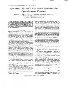
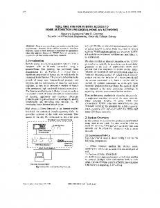
Fig. 1. A common PWM-controlled voltage multiplier.
I. INTRODUCTION
I
N high-voltage/low-current applications, such as TVCRT’s, lasers, X-ray systems, ion pumps, electrostatic systems, etc., a capacitor-diode voltage multiplier is usually preferable to a transformer with a large turns ratio and diodes with enormous breakdown voltages. A transformer with a large turns ratio is undesirable because it exacerbates the transformer nonidealities: the leakage inductance and the winding capacitance. These nonidealities cause voltage and current spikes and increase loss and noise. A common pulsewidth modulation (PWM)-controlled voltage multiplier [4] is shown in Fig. 1, where a buck converter is followed by a push–pull voltage multiplier. The main disadvantages of this converter are: 1) the circuit requires two stages including three switches and a complex control system, which increase loss and cost; 2) the input current is discontinuous, thus, input filter is invariably required to smooth out the switching ripple; and 3) high power factor is hard to realize with the buck preregulator. In this paper, we propose a novel single-stage high-voltage converter, which can be used to drive voltage multipliers. It eliminates the above drawbacks, reduces the size and cost, and increases the efficiency and reliability. The basic operation of the new converter is explained in Section II. Dynamic analysis and transfer functions are given in Section III. In Section IV, extensions for the basic threeswitch version are discussed. A soft-switching mechanism is explained in Section V. The experimental results are presented in Section VI, and the conclusion is given in Section VII. Manuscript March 11, 1996; revised December 2, 1996. Recommended by Associate Editor, K. Ngo. D. Zhou was with the California Institute of Technology, Pasadena, CA 91125 USA. She is now with the National Semiconductor Corporation, Santa Clara, CA 95052 USA. A. Pietkiewicz is with ASCOM Energy Systems, CH-3000, Berne 5, Switzerland. ´ is with the California Institute of Technology, Pasadena, CA 91125 S. Cuk USA. Publisher Item Identifier S 0885-8993(99)00280-X.
(a)
(b)
(c)
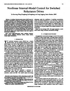
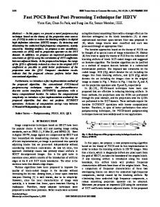
Fig. 2. The new three-switch HV converter: (a) the basic version, (b) the 00 equivalent circuit during s , and (c) the equivalent circuit during s.
DT
DT
II. BASIC OPERATION OF THE NEW CONVERTER A. Continuous Inductor Current Mode (CICM) The basic version of the HV converter is shown in Fig. 2(a). It appears like the Cuk converter, except that the output inductor of the Cuk converter is replaced by a diode. The cost for doing so is the loss of continuous output current, but in applications which require very high output voltage and small output current, the new converter gives substantial savings in size and weight. The basic operation for the converter is as follows. At the is turned on, the equivbeginning of each switching cycle, alent circuit is shown in Fig. 2(b). Since the voltage across is larger than that of , is turned on simultaneously is turned off by the negative output voltage across it. and is charging the output capacitor and the load resistor (note that the peak of the charging current is limited by and ). At the end of parasitic resistance in series with is turned off, the circuit is equivalent to that DT period, to turn on. of Fig. 2(c). The input inductor current forces is turned off by the negative output voltage. In Then, is being charged up by the inductor current this period, is being discharged to supply the load current. If the while can parasitics are neglected, the voltage conversion ratio
0885–8993/99$10.00 1999 IEEE
178
IEEE TRANSACTIONS ON POWER ELECTRONICS, VOL. 14, NO. 1, JANUARY 1999
(a)
(b)
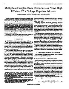
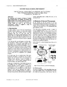
Fig. 3. The three-switch converter operates in DICM: (a) the third interval
i
L = 0 and (b) the input inductor current waveform. where
be easily derived as (1)
(7)
The new converter can also be developed from the boost converter by exchanging the position of the diode and the capacitor in the boost converter and adding another diode and an output capacitor. As a result, the new converter shares many similar properties with the boost converter. However, unlike the boost converter, the new converter can be easily extended to provide dc isolation and drive a capacitor-diode voltage multiplier. These features will be discussed later in Section IV.
(8)
B. Discontinuous Inductor Current Mode (DICM) and Automatic Current Shaping
(9) is the emulated resistance of the shaper. By keeping the duty ratio and switching frequency constant, the power factor is theoretically greater than 0.97 for conver, which is the same as the boost “automatic” sion ratio current shaper [5]. C. The Peak Capacitor Charging Current
If the input inductor current is discharged to zero before the end of the switching cycle, the converter is operating in discontinuous inductor current mode (DICM). The equivalent circuit in this interval is illustrated in Fig. 3(a) and the current waveform in Fig. 3(b). The steady-state analysis is the same as that of the boost converter [1]. The conversion ratio at DICM is
is charging directly through switches As in Fig. 2(b), and The peak charging current through can be approximately expressed as
(10) (2) where where the conduction parameter
is defined as (11) (3)
The converter operates in CICM when (4) and in DICM when (5) For off-line applications, the new converter can work as an “automatic” current shaper when operating in DICM. The input inductor current averaged over one switch period is given by
(6)
and are the ESR associated with and , respecequals the sum of tively. The peak current through and the inductor current. Increasing the capacitance reduces the peak current and power loss. Increasing ESR values also reduces the peak current, but will increase the power loss. is to insert Another way to reduce the peak current and a small inductor (e.g., [9]) or saturable reactor in series with the capacitor III. SMALL-SIGNAL DYNAMICS The method of state-space averaging [1] or averaged switch model [2] can be used to determine the dynamic responses for the three-switch converter [Fig. 2(a)]. The state-space averaging technique is justified by the assumption of the linear capacitor voltage ripple, which requires the time constant of capacitor charging loop to be sufficiently longer than the switching period, i.e.,
ZHOU et al.: THREE-SWITCH HIGH-VOLTAGE CONVERTER
179
The control-to-output-voltage transfer function is found as
(12) Fig. 4. A capacitor-diode quadrupler extension of the basic three-switch HV converter.
where (13) (14) (a)
(15) (16) (17) (b)
(18) (19) is separated The double right-half plane (RHP) zero and the two zeros are into two real zeros when (20) (21) is exactly the same RHP zero as that for a boost Note that is normally at a much higher frequency converter, and range. Also, the line-to-output transfer function is given by
(22)
If the time constant of capacitor charging loop is comparable to the switching cycle, the linear ripple assumption is not satisfied. Therefore, the state-space averaging method does not apply. However, the expression for the dominant double poles remains the same as in (17) since they are caused by the resonance between input inductor and the two capacitors, The accurate small-signal analywhich are independent of sis in the higher frequency range can be carried out by using the method of state-space analysis without the linear ripple approximation. The results should be computed numerically since the symbolic expressions for matrices exponential are too involved to be useful.
(c) Fig. 5. An extension of the three-switch HV converter with (a) continuous input and output currents, (b) the equivalent circuit during DTs , and (c) the equivalent circuit during D0 Ts :
IV. EXTENSIONS OF THE BASIC THREE-SWITCH CONVERTER The first extension of the basic three-switch converter is adding a capacitor-diode voltage multiplier at its output. A quadrupler version of the HV converter is shown in Fig. 4. Generally, for an -stage The output voltage is (one stage consists of two diodes multiplier, and two capacitors). By using the voltage multiplier, the voltage stress on each switch or capacitor is reduced. Since fast diodes with enormous reverse voltage ratings are hard to find, reduction of the diode ratings decreases the reverse-recovery current in each diode. However, all the diodes are in series with the output at dc (when capacitors can be considered as open branches since no averaged dc current goes through them), and the on loss caused by the forward voltage drop of the diodes is increasing. Also, the capacitance charging loss increases with the number of stages. In addition, output voltage ripple and the dc output resistance increase rapidly with the increasing of [6]. Therefore, after choosing reasonable voltage ratings for devices, the minimum number of stages should be used to reduce loss and output voltage ripple. In the applications which need enormous step-up ratio, a transformer may be used together with the capacitor diode voltage multiplier to provide the required output voltage. The full dynamic analysis for the voltage multiplier in Fig. 4 will not be discussed in this paper. However, it is worthwhile to give the dominant double poles, which can be simply
180
IEEE TRANSACTIONS ON POWER ELECTRONICS, VOL. 14, NO. 1, JANUARY 1999
Fig. 6. The dc isolated three-switch converter. The input inductor can be coupled with the transformer.
Fig. 8. Theoretical (line) and experimental (dot) dc gain characteristics of the three-switch HV converter in CICM. (a)
(b) Fig. 9. Verification of the conduction mode type and dc gain in the three-switch converter in DICM when duty cycle is less than 0.65. Theoretical (line) and experimental (dot).
(c) Fig. 7. Soft-switching mechanism: (a) bidirectional inductor current, (b) resonant interval #1, and (c) resonant interval #2.
expressed as (23)
its harmonics. So, and are effectively in parallel and have identical ac-voltage waveforms. Hence, the two inductors can be coupled to reduce size and provide the ripple-steering feature. This converter can be viewed as an extension of the Cuk converter by inserting a voltage doubler before the output inductor. The conversion ratio for this converter is , which can be easily derived from equivalent circuits of the and [Fig. 5(b) and (c)]. converter in intervals In comparison with the basic Cuk converter, the new converter operates at lower duty ratio for the same overall conversion ratio. The relation between the respective duty and is obtained from ratios (24)
is defined as in (13). where This result can be extended to the -stage voltage multiplier, capacitances replacing that of the with the summation of all four capacitances in (23). The physical insight is as follows: at low frequency, all capacitors function as though they are in parallel. The total capacitance is resonant with the equivalent inductance, which gives rise to the dominant double poles. Another interesting converter developed from the threeswitch HV converter is shown is Fig. 5, where both the input and and output current are continuous. The input inductor are in a loop with and the output inductor which appear as short circuits at switching frequency and
which leads to (25) is always lower than ( is greater than 0.5 Clearly, when the Cuk converter works as a step-up converter.) The voltage stress on the transistor and diodes is (26) which is half of the switch stress in the basic Cuk converter.
ZHOU et al.: THREE-SWITCH HIGH-VOLTAGE CONVERTER
181
(a) Fig. 10.
(b)
Measured (solid lines) and predicted (dashed lines) control-to-output-voltage transfer function: (a)
The peak voltage stress on
and
D equals 0.5, and (b) D equals 0.7.
is (27)
which is less than half of that in the basic Cuk converter. Theoretically, a capacitor-diode multiplier with more stages (such as a quadrupler) can be inserted in place of the doubler in Fig. 5. However, this will introduce more losses as explained at the beginning of this section. For many applications, it is essential to provide dc isolation between input and output and/or multiple outputs of different voltages and polarities. Similar to the Cuk converter, the threeswitch HV converter and its extensions have an energy transfer capacitor. By splitting this capacitor into two in series, we can easily insert an ac transformer between the two capacitors. An isolated three-switch HV converter is shown in Fig. 6, where the input inductor and the transformer can be coupled. In the isolated version of the converter in Fig. 5, all the magnetics (input and output inductors and transformer) can be coupled.
Fig. 11. Theoretical (line) and experimental (dot) dc gain characteristics of the quadrupler extension.
V. ZERO-VOLTAGE SWITCHING For a hard-switching converter, in every switching cycle, charge stored in the junction capacitance during the turn-off transition is dumped into the transistor at the beginning of the transistor turn on. This switch turn-on loss is proportional to the switching frequency. It becomes significant at highswitching frequency and high-voltage applications. Moreover, the discharging current introduces high-current spike and high in the transistor, which result in high-switch stress and electromagnetic interference (EMI) noise. In order to achieve zero-voltage switching at constant switching frequency, the in the converter from Fig. 2 is replaced with the diode Soft-switching of both transistors is provided MOSFET by discharging the junction capacitor across the MOSFET before it is turned on [7]. The simplest way is to design the input inductor such that its current is bidirectional (the peak-to-peak ripple current greater than twice of its average dc current at maximum load). During the transition periods, all the switches are off and the input inductor and the two junction capacitors exchange energy in the lossless resonant mode to realize zero-voltage switching. The mech-
Fig. 12. Theoretical (line) and experimental (dot) dc gain characteristics of the continuous input and output currents extension.
anism for soft switching is illustrated in Fig. 7(a)–(c) and explained next. The bidirectional input current is shown in Fig 7(a). Two and are introduced by delaying the resonant intervals turn on of one switch after the turn off of the other. The resonant intervals are assumed to be short compared with the switching period. Therefore, the input inductor can be replaced by current source in Fig. 7(b) and (c). Each MOSFET is replaced by a composite switch, consisting of a main switch, an antiparallel diode, and a junction capacitor. The energy transfer capacitor is replaced by a constant voltage source. starts when is open. The first resonant interval is open simultaneously. The positive peak input current is and discharging When the voltage on charging is discharged to zero, conducts and clamps the voltage at can be turned on at zero voltage. zero. Now,
182
IEEE TRANSACTIONS ON POWER ELECTRONICS, VOL. 14, NO. 1, JANUARY 1999
(a)
(b)
(c)
(d)
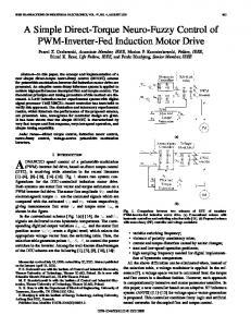
Fig. 13. Comparison of the three-switch converter with or without soft switching. In each oscillogram photograph: (a) upper trace: input inductor current (5 A/div), (b) upper middle trace: drain-to-source current (5 A/div), (c) lower middle trace: drain-to-source voltage (20 v/div), and (d) lower trace: gate voltage (10 v/div); time scale: 2 �s/div.
The second resonant interval starts when is turned is negative now, is discharged off. The input current is charged toward Since is toward zero, and is always longer than There is another smaller than , will never conduct. difference from the first transition: This can be explained by looking at the loop consisting of and At the beginning of , is When (turn-on always bigger than ), would turn on first. The capacitor charging voltage of current is usually bigger than the negative inductor current, the , and will difference of these two currents will charge before never reach zero. Therefore, we should turn on Fortunately, the difference between and is usually very is turned on very close to zero voltage. small, thus, The resonant transitions also provide zero-voltage turn off and reduces the loss caused by the reverse recovery for current in VI. EXPERIMENTAL RESULTS First, a prototype of the basic three-switch converter was built to verify analytic results. Components used in this IRF prototype are listed below: ERC H F and The measured and predicted dc-voltage conversion ratios V and kHz). are shown in Figs. 8 and 9 ( and the converter is always in CICM. In Fig. 8, The deviation at the high end of the duty cycle is due to the parasitics (lossy elements) inside the converter. When
equals 630 , the converter goes into DICM when the duty ratio is less that 0.65, which is consistent with the result from Since (4) or (5): operating in DICM when the load current is very small in this case, the parasitic elements have a negligible effect as shown in Fig. 9. Fig. 10 gives the measured control-to-output transfer funckHz), together with the theoretical tions (where predictions from Section III. Good agreements can be observed up to half of a switching frequency. The voltage conversion ratios of the two extensions of the basic three-switch converter (from Figs. 4 and 5) were measured. Results are displayed in Figs. 11 and 12. Finally, experiments were done to demonstrate the softswitching mechanism. Waveforms with and without soft switching are shown in Fig. 13(a)–(d) for comparison. In the experimental circuit, the drain-to-source voltage of each MOSFET is sensed to control the corresponding gate signal. is close to zero. Each MOSFET is turned on when its In Fig. 13(a), it can be seen that the current goes through when is turned on. Therefore, is turned on without switching losses. In Fig. 13(c), negative input inductor to a negligible small value and the current discharges on before starts to conduct. control (gate) signal turns conducts, is turned on. The current through After is the summation of the input inductor current and the output capacitive charging current. The high-current spike and oscillation in the hard-switched converter are eliminated by use of the soft-switching technique. V, The measured efficiency (when mA) is 92%.
ZHOU et al.: THREE-SWITCH HIGH-VOLTAGE CONVERTER
VII. CONCLUSION A novel three-switch HV converter derived from the Cuk converter is discussed in this paper. It has the boost-like front end. Automatic current shaping is obtained by operating the converter in DICM. DC and dynamic analyses reveal that it has many similarities to the boost converter. However, exchanging of the position of the diode and capacitor in the boost converter provides significant benefits due to the floating capacitor. First, it can be used to drive a capacitor-diode multiplier, which is the common solution for ultrahigh-voltage application. Second, the isolation of input and output can be easily achieved as in a Cuk converter by splitting the energy transfer capacitor into two and inserting an ac transformer in between. Another interesting extension, which features both continuous input and output current, is also introduced. The inductors in this converter can be coupled. Experimental results agree well with the predictions. REFERENCES [1] R. D. Middlebrook and S. Cuk, “Advances in switched-mode power conversion,” vols. I–III, TESLAco, 1981. [2] D. Zhou, “Analysis of a three-switch high-voltage converter,” Tech. Notes #225, Power Electronics Group, Calif. Instit. Technol., Pasadena, Feb. 1992. [3] W. T. Harrigill, Jr. and I. T. Myers, “Regulation of a lightweight high efficiency capacitor diode voltage multiplier dc–dc converter,” in IEEE PESC Rec., 1976, pp. 186–189. [4] T. K. Phelps, “Optimizing the design of switch-mode power conditioners using capacitive voltage multipliers,” in Proc. Powercon, vol. 8, 1981, pp. 1–7. [5] S. D. Freeland, “Input current shaping for single-phase ac–dc power converters,” Ph.D. dissertation, pt. II, Calif. Instit. Technol., Pasadena, 1988. [6] P. M. Lin, and L. O. Chua, “Topological generation and analysis of voltage multiplier circuits,” IEEE Trans. Circuits Syst., vol. CAS-24, no. 10, pp. 517–530, 1977. [7] H. C. Martin and D. W. Parsley, “Zero-voltage switching in high frequency power converters using pulse width modulation,” in IEEE APEC Rec., 1988, pp. 33–40. [8] W. T. Harrigill, Jr. and I. T. Myers, “Efficiency and weight of voltage multiplier type ultra lightweight dc-dc converters,” in IEEE PESC Rec., 1975, pp. 31–37. [9] F. C. Schwarz, J. B. Klaassens, and W. Petiet, “An efficient 600 watt high voltage capacitor multiplier,” in IEEE PESC Rec., 1980, pp. 316–325. [10] K. D. T. Ngo and R. Webster, “Steady-state analysis & design of a switched-capacitor dc–dc converter,” in IEEE PESC Rec., 1992, pp. 378–385.
183
Dongyan Zhou (S’91–M’96) received the B.S. degree in electrical engineering from Zhejiang University, China, in 1989 and the M.S. and Ph.D. degrees in electrical engineering from the California Institute of Technology, Pasadena, in 1992 and 1995, respectively. Since 1995, she has been with National Semicondutor, Santa Clara, CA. Her areas of interest include switching converter topologies, modeling and control of switching converters, and power factor corrections. Dr. Zhou is a Member of Sigma Xi.
Andzrej Pietkiewicz received the B.S., M.S., and Ph.D. degrees in electrical engineering from the Technical University of Gdansk, Poland. From 1975 to 1989, he was a Teaching and Research Assistant and, later, a Faculty Member of the Technical University of Gdansk. In 1989, he received the Post-Doctoral Fulbright Fellowship and joined the Power Electronics Group, California Institute of Technology, Pasadena, as a Visiting Faculty Member. In 1991, he joined Ascom Energy Systems, Switzerland, where he is a Project Leader in the R&D Department. He is an author and coauthor of 30 papers and hold six patents. His main research interests include high-frequency power conversions, new converter/inverter topologies, single- and three-phase power factor correctors, distributed power systems, and UPS systems.
´ Slobodan Cuk (M’77–SM’95–F’96) received the B.S.E.E. degree from Belgrade University, Belgrade, Yugoslavia, in 1970, the M.S.E.E. degree from the University of Santa Clara, Santa Clara, CA, in 1974, and the Ph.D. degree from the California Institute of Technology, Pasadena, in 1976. He is an Associate Professor of Electrical Engineering at the California Institute of Technology. He conducts research in electrical energy processing systems and teaches courses in power electronics and fundamentals of energy processing. His publications include over 100 scientific papers in the power electronics field and a three-volume book on switched-mode power conversion. ´ Dr. Cuk received the IR*100 Award in 1980 from the Industrial Research Magazine for the invention of a new switching converter topology, now ´ known as the CUKonverter, and several of its extensions. For the invention of integrated magnetics and expediting the development of switched-mode power converters, he received the 1991 Edward Longstreth Medal from the Franklin Institute.