SCTP. Stream Control Transmission Protocol. SSH. Secure SHell. TCP. Transmission Control Protocol. TFTP. Trivial File Transfer Protocol. TOS. Type Of Service.
Practical Issues of Implementing a Hybrid Multi-NIC Wireless Mesh-Network
Mesut Güne³
Bastian Blywis
Felix Juraschek
Philipp Schmidt
Computer Systems and Telematics Institute of Computer Science Freie Universität Berlin, Germany
{guenes,blywis,jurasch,phils}@inf.fu-berlin.de
Technical Report TR-NO: TR-B-08-11
August, 2008
Institute of Computer Science, Freie Universität Berlin, Germany
2
Contents List of Acronyms
vii
1 Introduction
5
1.1
Motivation . . . . . . . . . . . . . . . . . . . . . . . . . . . . . . . . . . . .
5
1.2
Summary of the DES testbed
. . . . . . . . . . . . . . . . . . . . . . . . .
5
1.3
Structure of the paper
. . . . . . . . . . . . . . . . . . . . . . . . . . . . .
7
2 Software Architecture and Management
9
2.1
Testbed Server
. . . . . . . . . . . . . . . . . . . . . . . . . . . . . . . . .
9
2.2
Boot Process
. . . . . . . . . . . . . . . . . . . . . . . . . . . . . . . . . .
10
2.3
File System Organization . . . . . . . . . . . . . . . . . . . . . . . . . . . .
11
2.4
User Administration
. . . . . . . . . . . . . . . . . . . . . . . . . . . . . .
12
2.5
Experiments . . . . . . . . . . . . . . . . . . . . . . . . . . . . . . . . . . .
12
3 Technical Aspects 3.1
3.2
3.3
15
Linux Network Stack . . . . . . . . . . . . . . . . . . . . . . . . . . . . . . 3.1.1
Sockets . . . . . . . . . . . . . . . . . . . . . . . . . . . . . . . . . .
16
3.1.2
Routing Basics and Packet Handling
. . . . . . . . . . . . . . . . .
16
3.1.3
Netlink Inter Process Communication . . . . . . . . . . . . . . . . .
20
. . . . . . . . . . .
21
3.2.1
General Routing Protocol Implementation Approaches Limitations and Di�erences
. . . . . . . . . . . . . . . . . . . . . .
22
3.2.2
Layer 2.5 Approaches . . . . . . . . . . . . . . . . . . . . . . . . . .
22
3.2.3
Related Work . . . . . . . . . . . . . . . . . . . . . . . . . . . . . .
23
3.2.4
Outlook
24
. . . . . . . . . . . . . . . . . . . . . . . . . . . . . . . . .
IEEE 802.11 Stack
. . . . . . . . . . . . . . . . . . . . . . . . . . . . . . .
4 Practical Experiences & Pitfalls 4.1
4.2
15
24
27
Antenna Separation . . . . . . . . . . . . . . . . . . . . . . . . . . . . . . .
27
4.1.1
Basic Setup
28
4.1.2
Network Topology and Environment
. . . . . . . . . . . . . . . . .
28
4.1.3
Interference
. . . . . . . . . . . . . . . . . . . . . . . . . . . . . . .
28
4.1.4
USB Throughput . . . . . . . . . . . . . . . . . . . . . . . . . . . .
29
4.1.5
WLAN Throughput and Delay
. . . . . . . . . . . . . . . . . . . .
29
4.1.6
. . . . . . . . . . . . . . . . . . . . . . . . . . . . . . .
Multi-Transceiver Comparison . . . . . . . . . . . . . . . . . . . . .
30
Network to Data Link Layer Mapping . . . . . . . . . . . . . . . . . . . . .
31
4.2.1
ARP Flux . . . . . . . . . . . . . . . . . . . . . . . . . . . . . . . .
31
4.2.2
Experienced Symptoms . . . . . . . . . . . . . . . . . . . . . . . . .
32
4.2.3
Impact on Experiments . . . . . . . . . . . . . . . . . . . . . . . . .
33
i
ii
Contents 4.2.4
Operation System Speci�c Design Reasons . . . . . . . . . . . . . .
4.2.5
Solution Approaches
. . . . . . . . . . . . . . . . . . . . . . . . . .
34
. . . . . . . . . . . . . . . . . . . . . . . . . . . . . . . .
35
4.3
Network Booting
4.4
Time Synchronization
4.5
Universal Serial Bus
5 Conclusion
33
. . . . . . . . . . . . . . . . . . . . . . . . . . . . .
36
. . . . . . . . . . . . . . . . . . . . . . . . . . . . . .
36
39
List of Figures 1.1
DES-Mesh Testbed Architecture . . . . . . . . . . . . . . . . . . . . . . . .
6
2.1
File System Organization . . . . . . . . . . . . . . . . . . . . . . . . . . . .
12
3.1
Linear Packet Space
. . . . . . . . . . . . . . . . . . . . . . . . . . . . . .
18
3.2
Net�lter Hooks
. . . . . . . . . . . . . . . . . . . . . . . . . . . . . . . . .
20
4.1
Map and topology of the experiment setup. . . . . . . . . . . . . . . . . . .
28
4.2
Spectrum of three NICs using orthogonal channels . . . . . . . . . . . . . .
29
4.3
Single-transceiver throughput and delay.
30
4.4
Multi-transceiver throughput over 4 hops.
. . . . . . . . . . . . . . . . . .
30
4.5
ARP Problem Example . . . . . . . . . . . . . . . . . . . . . . . . . . . . .
32
iii
. . . . . . . . . . . . . . . . . . .
iv
List of Figures
List of Tables 4.1
Multi-transceiver throughput using 3 disjoint router pairs . . . . . . . . . .
v
30
vi
List of Tables
List of Acronyms AODV
Ad-hoc On-demand Distance Vector
ARP
Address Resolution Protocol
ASlib
A library with the goal to help developers to
ATM
Asynchronous Transfer Mode
BGP
Border Gateway Protocol
CST
Computer Systems and Telematics
DES
Distributed Embedded Systems
implement mesh-/manet protocols
DHCP
Dynamic Host Con�guration Protocol
DLL
Data Link Layer
DNS
Domain Name System
DSL
Domain Speci�c Language
ESSID
Extended Service Set IDenti�er
FDDI
Fiber Distributed Data Interface
FIB
Forwarding Information Base
ICMP
Internet Control Message Protocol
IEEE
Institute of Electrical and Electronics Engineers
IGMP
Internet Group Management Protocol
IP
Internet Protocol
IPC
Inter Process Communication
ISP
Internet Service Provider
MTU
Maximum Transmission Unit
NFS
Network File System
NIC
Network Interface Card
NTP
Network Time Protocol
vii
List of Acronyms OFDM
Orthogonal Frequency Division Multiplex
OS
Operating System
OSPF
Open Shortest Path First
PHY
Physical Layer
PXE
Preboot eXecution Environment
QoS
Quality of Service
RPDB
Routing Policy Database
RSSI
Received Signal Strength Indicator
SCTP
Stream Control Transmission Protocol
SSH
Secure SHell
TCP
Transmission Control Protocol
TFTP
Trivial File Transfer Protocol
TOS
Type Of Service
UDP
User Datagram Protocol
USB
Universal Serial Bus
WEP
Wired Equivalent Privacy
WLAN
Wireless Local Area Network
WMN
Wireless Mesh Network
WPA
Wi-Fi Protected Access
WSN
Wireless Sensor Network
1
2
List of Acronyms
Abstract Testbeds are a powerful tool to study wireless mesh and sensor networks as close as possible to real world application scenarios.
In contrast to simulation or analytical approaches
these installations face various kinds of environment parameters. Challenges related to the shared physical medium, operating system, and used hardware components do arise. In
Distributed Embedded Systems testbed of 100 routers deployed at the Freie Universität Berlin we focus on the software architecture this technical report about the work-in-progress
and give an introduction to the network protocol stack of the Linux kernel. Furthermore, we discuss our �rst experiences with a pilot network setup, the encountered problems and the achieved solutions. This writing continues our �rst publication and builds upon the discussed overall testbed architecture, our experiment methodology, and aspired research objectives.
3
4
List of Acronyms
CHAPTER 1
Introduction 1.1
Motivation
Wireless networks have been an emerging technology since the last two decades. While all of them shall enable communication between remote hosts over a shared wireless broadcast medium, their technologies, network topologies and characteristics are manifold. One of the prominent kinds of networks are the wireless mesh networks (WMN). They are set up by non-pro�t communities, by Internet Service Providers (ISP), or by individuals in rural areas. The most important application scenario of WMNs is to provide network access to arbitrary groups of users. Mesh networks usually posses a stationary core network that routes data towards gateway nodes or vice versa to a client. Routing in wireless networks has to deal with the properties of the wireless medium.
The bit error rates are many
times higher than in wired networks. Links cannot be assumed to be bidirectional or to provide the same bandwidth in both directions. Further on, due to the mobility of clients or arbitrary objects, e�ects like temporary loss of connection and short-term fading have to be considered.
To study these issues testbeds are a viable option.
While they are
limited in scalability, they do not rely on models abstracting from real world properties as do simulators. Thus, the usage of real hardware and operating systems ensure research as close to reality as possible. In this report we discuss the hybrid wireless Distributed Embedded Systems (DES) testbed that supports holistic research of wireless networks. We focus on the physical and technical aspects that have been of interest in the setup phase. With this publication we continue our introduction of the DES testbed [1]. This paper has several goals. On the one hand, we want to report our �rst experiences and the encountered problems. On the other hand, students that plan to do their thesis in the Computer Systems and Telematics (CST) work group shall be introduced to the relevant topics. We pursue to minimize the needed training period with our writing.
Chapter 3 is of special interest for anybody
interested in doing a routing protocol implementation or kernel related modi�cations. The following section summarizes the most important information that are required for the understanding of this writing.
1.2
Summary of the DES testbed
The DES testbed is a hybrid network. The nodes of our network contain a small formfactor mainboard equipped with an Intel x86 compatible CPU and at least three network
5
6
Chapter 1. Introduction
Figure 1.1: Architecture of the hybrid testbed consisting of mesh routers, mesh clients, sensor nodes, and management component. Sensor nodes may be connected with wired extensions.
cards compliant to the Institute of Electrical and Electronics Engineers (IEEE) 802.11b/g standard. The network interface cards (NIC) are connected via universal serial bus (USB) using a powered hub. The focus on USB devices instead of Mini PCI achieves virtually unlimited expandability for future extensions. We call the corresponding network built by these wireless mesh routers DES-Mesh. Contained in the same enclosure are one or more wireless sensor network (WSN) nodes creating a second in parallel testbed to the WMN. The sensor network testbed is named DES-WSN and consists of hardware based on an ARM7 core and Chipcon CC1100 transceiver.
The combination of a multi-transceiver
WMN and WSN will be referred to as DES testbed. This setup distinguishes our testbed from others. At the time of the writing the DES testbed is in the process of setup with a pilot network of 35 routers located in the computer science institute of the
Freie Univeristät Berlin.
In the �nal stage up to 100 will be deployed comprising several of the adjacent buildings. The network has the property of being persistent as it is a permanent installation. As depicted in Figure 1.1 our overall architecture is a three layered one. The stationary mesh routers make up layer 1 while the mobile clients of the network are layer 2. Subsequently, the sensor nodes form layer 3. We do not make any speci�cations but leave the decision whether mesh clients and sensor nodes route to the application. We plan to use mobile phones, laptops, and PDAs as mobile hosts for experiments. The network is therefore partially mobile while the stationary routers are always present. The topology is con�gurable. The last component of the DES testbed is the testbed server which is the central management, monitoring, and experimentation platform and stores all vital data. For further detailed information about the DES testbed architecture, hardware, and
1.3. Structure of the paper
7
experiment methodology the reader is referred to our previous technical report [1].
1.3
Structure of the paper
The remainder of this Technical Report is structured as follows. In Chapter 2 we introduce the overall software architecture of our testbed infrastructure including topics related to the testbed server as well as concerning the mesh routers. We continue in Chapter 3 with an overview of the Linux kernel with the focus on the network stack and a discussion about the di�erent routing protocol implementation approaches. Subsequently, in Chapter 4 we discuss our �rst practical experience with the testbed hardware and encountered pitfalls. Viable solutions are o�ered. The paper closes in Chapter 5 with some conclusions.
8
Chapter 1. Introduction
CHAPTER 2
Software Architecture and Management This chapter describes the software architecture applied to the di�erent components of the DES testbed. We present the particular operating systems and con�guration of the testbed server, mesh routers, and sensor nodes. Finally, we elaborate our approaches to support a multi-user environment and how experiments are actually performed on the DES testbed.
2.1
Testbed Server
Our testbed server consists of a virtual server with the hostname UHU located in the network of the
Freie Universität Berlin. A Debian Linux distribution of version 4.0 (Etch)
is installed as the Operating System (OS). UHU is connected to the university network via Ethernet and is only accessible from hosts in this particular network. UHU can access the world-wide Internet over the university network. At the time of this writing, UHU provides manifold services; on one hand for the mesh routers and sensor nodes forming the hybrid testbed and on the other hand for the maintainers and users of the testbed. UHU provides a Dynamic Host Con�guration Protocol (DHCP) service, which assigns a static Internet Protocol (IP) address to each mesh router according to the MAC address of its Ethernet network interface. With the acquired network layer address a mesh router can mount the root �le system via the network �le system (NFS) protocol, which is also located on UHU. In the following sections the boot process as well as the organization of the root �le system of the mesh routers is described. The hostname of a mesh router is determined by a simple system which takes its location into account. It is composed of the name of the building and the room number, in which the mesh router is placed. For instance the mesh router with the hostname is located in our institute building
Takustrasse 9
in room number
157.
t9-157
In combination
with dnsmasq [2], a light-weight Domain Name System (DNS) server, the nodes can be addressed with the issued hostname, which is much more comprehensible and convenient for experimenters than using the IP address. Access to the testbed server is provided in a twofold way for testbed maintainers and users. A Secure SHell (SSH) daemon is running on UHU which enables remote administration of the testbed server. This shell access is restricted to the testbed maintainers. User management of the testbed experimenters is a task of the
DES-EXP web application
which is integrated into our webserver architecture. At the moment this architecture consists of an Apache2 and a Tomcat server. The
9
10
Chapter 2. Software Architecture and Management
Apache2 server listens on port 80 and depending on the URL redirects the requests to the corresponding server.
In the case of the
DES-EXP
application the request will be
redirected to the Tomcat server which hosts the application, which is implemented as an servlet in Java and therefore depends on a Java Server-Engine.
DES-EXP
as described
in [1] provides the interface to create, upload, and execute experiments. Further on, it can be used to download or evaluate measured data.
We chose this approach and did
not install just a single Tomcat server because we also want to host various other web applications on a di�erent platform than the Java Servlet-Engine. With our webserver architecture we can easily expand the o�ered web services and are not restricted to a single platform.
We will add a forum, a bug tracking component, and a Wiki to our
web services soon.
The Wiki will feature useful information about the testbed and its
con�guration and manuals about the management components. Its content is aimed at students who take part in the lab exercises and is also meant as an introduction for the research sta�. Finally, the testbed server hosts a PostgreSQL database, in which logging data of the testbed operation will be saved for further investigation.
For this purpose we will use
a Round Robin Database (RRD) tool, which allows us to get periodic data about the network state. Results of experiments will also be stored in the database, which is used for evaluation and as input for the visualization tool
2.2
DES-VIS.
Boot Process
All mesh nodes are diskless to minimize the points of failure and to reduce costs. The primary of the two Ethernet network interfaces of the Alix2c2 mainboard can be con�gured to boot over the network.
The router sends DHCP requests that are answered by the
testbed server. The mapping of MAC to IP addresses is con�gured statically at the time of this writing. After receiving a DHCP response, the router learns its layer 3 address, the subnet, and information about the next step of the process. This includes the IP address of a server o�ering a bootable OS image. In our case this is also the testbed server. The router downloads a Preboot eXecution Environment (PXE) image via the Trivial File Transfer Protocol (TFTP) to continue with the next step. The SYSLINUX [3] derivative PXELINUX is utilized to download the real Linux kernel that is stored in the RAM of the router. After decompression, the control is handed over to this kernel. Due to the kernel parameters an IP address is requested via DHCP again. The same IP address is assigned as the �rst time. The root �le system is then mounted via NFS and the standard kernel boot-up procedure takes place. During the System V initialization the network interfaces are brought-up by the kernel. A third time the same IP address is acquired via DHCP. After this step the router is a fully functional node of the testbed. consists of the following steps: 1. Mesh router is switched on 2. Mesh router boots over the network 3. Download of PXE image 4. Download of Linux kernel image 5. Standard kernel boot-up procedure
The whole process
2.3. File System Organization
11
Although it seems unnecessary to acquire the same IP address three times during startup, the whole process is straight forward and applies to the common default approach. Due to this con�guration mesh routers can be easily deployed in arbitrary rooms or relocated without changes to the OS. As we will discuss in Section 2.3 the only information that has to be updated is the hostname of the mesh router stored on the testbed server.
2.3
File System Organization
The mesh routers use multiple �le systems. All mesh routers share a root �le system that is provided over NFS by the testbed server and is mounted read-only. This avoids
write
after write hazards and ensures a sane root �le system as no entity but the testbed server can modify it.
We pursue the approach that every router shall have as little rights as
possible and just as much as necessary. Furthermore, the shared root �le system simpli�es management and updates of the OS as we need to do tasks just in one location. Anyhow, the Linux system needs write access to some directories and �les. The most prominent example is the
tempfs
/tmp directory where temporary �les are stored.
For this cause
is utilized which uses virtual memory that can be mounted like a normal �le
system. Everything in this directory is lost after a reboot.
/tmp is mounted by default by
the Debian distribution. There are other locations for which the mesh routers need write
/var/run. /tmp and use symbolic links (symlinks ) to map them. the directory /ro, where template �les are stored, to
permission but normally would be part of the root �le system. An example is We create these as subdirectories in For this, we copy the content of
/tmp during the boot process.
This is necessary as the corresponding directories and �les
have to exist and are not created on demand. Log �les needed for evaluation and error diagnosis have to use persistent storage. Logs are normally stored in
/var/log.
The testbed server provides individual NFS exports for
each router that are named after their hostnames. The routers mount the corresponding network drive to mapped via
symlinks
/mnt/data during the boot process. Directories like /var/log are to the /mnt/data entries. As the information of all routers is stored
on the testbed server we can easily access these with shell scripts to evaluate measured data or to diagnose errors. Our approach might seem complex on the �rst sight but the mentioned advantages are bene�cial for the management of the testbed and experiment execution. The whole con�guration is shown in Figure 2.1. In summary, we divide the root �lesystem into the following parts:
temporary data: persistent data:
These data are lost after reboot and mounted as
tempfs.
Each mesh router has its own writable data area that is mounted
via the NFS protocol, provided by the testbed server.
root:
Everything else is read-only and shared by all mesh routers mounted as NFS.
The �le system organization makes the DES-Mesh testbed scalable beyond the envisioned 100 routers and sets the foundation for extensive network wide experiments.
12
Chapter 2. Software Architecture and Management / persistent (stored on testbed server)
etc
resolv.conf mnt data var log ro tmp
temporary (created as tempfs)
etc var
var
resolv.conf lock run
lock log run
Figure 2.1: File system organization of the mesh routers.
The arrows with solid lines
depict symbolic links while the dashed one symbolizes a copy action.
2.4
User Administration
As already brie�y described, we enforce a twofold user management system by strictly separating users who want to perform experiments from the testbed maintainers and administrators.
Shell access via SSH is restricted to the latter group and due to the
connection to the Internet, software updates can be easily done. With the
sudo command
we are able to grant (selected) superuser rights to a particular user needed to perform maintenance tasks. Testbed users do not have a shell account for the Linux system and are managed by our management component. Testbed administrators can create, modify, and delete testbed users within the
DES-EXP
application. Thereby, we are able to grant rights or
utter restrictions to speci�c users, which becomes especially useful, when di�erent users should be able to address only particular subsets of testbed nodes when working on lab assignments simultaneously.
2.5
Experiments
DES-EXP management console experiments can be created as described in detail Each experiment consists of a description written in DES-CRIPT and additional
With the in [1].
�les such as kernel modules, shell scripts and binary programs which will be executed during the experiment. To keep track of each experiment, general information such as the experiment id, its status, and the starting time will be saved in the PostgreSQL database which ensures an easy access for the experiment scheduler. each experiment is created in
DES-CRIPT
Next to that, a folder for
/des/experiment/
which contains the
description and all additional �les.
When an experiment is started, the preparation of the testbed begins by interpreting the experiment description. First, possible changes to the root �le system of the mesh routers have to be carried out. As for now, we do not support self-compiled kernel images
2.5. Experiments
13
but provide a variety of di�erent kernel images of which the user can select one. Support of self-compiled kernel images is scheduled as future work. There are many options to ensure that the mesh routers can boot di�erent kernel images without the need to clone the entire root �le system. The DHCP and TFTP �les can be modi�ed accordingly so that it is possible to specify the kernel image which will be booted depending on the MAC address of the mesh router. After the reboot process the additional �les will be copied into the root �le system of the mesh routers.
The
mesh router loads the kernel modules, either custom ones supplied by the user or already installed ones. The support of custom kernel modules is essential for many experiments, for example for the development of routing algorithms. Besides that the user can choose between several already installed modules. During the experiment execution the testbed server interacts with the mesh routers via SSH connections. Actions de�ned in the experiment description will be triggered at the speci�ed times or when given conditions are met. Once the experiment is �nished the testbed server gathers the log �les of the mesh routers to make them accessible for further investigation by the user or automated evaluation. For nodes with a permanent Ethernet connection, the log �les are already contained in the testbed server's �le system. Therefore, copy operations are only required to save all log �les to the speci�ed experiment folder. Data can also be inserted into the database. We accomplish this by supporting user de�ned evaluation scripts, which process the log �les of the mesh routers and perform database insertions accordingly. We refrain from the idea to let the mesh router directly access the database in real time, since not all mesh routers will have permanent Ethernet connection. Therefore, all measured data will be written to log �les �rst and processed after the experiment. Finally, after �nishing an experiment the testbed server starts a restoration procedure to reset the testbed in its default and well-de�ned state. As part of this procedure the testbed server removes the experiment speci�c �les from the root �le system of the mesh routers and restores its con�guration. Subsequently, the mesh routers are rebooted using the default kernel image. The same restoration procedure takes place when exceptions occur during an experiment. Due to our conservative error handling approach, an experiment will be aborted as soon as errors or misbehavior are detected.
Log �les, if available, are copied to the
experiment folder on the testbed server which may be useful to �nd the reason that lead to the abortion. The status of the experiment will be marked as failed in the corresponding database entry.
14
Chapter 2. Software Architecture and Management
CHAPTER 3
Technical Aspects Linux is a complex and feature-rich OS developed over a time span of 15 years by countless people. In this chapter we will introduce the most important aspects about the kernel. Due to our focus on networking we will discuss the overall network stack architecture and the most important related properties. We will particularly have a look at di�erent approaches on how to implement routing protocols. The chapter ends with a short section about the new IEEE 802.11 wireless stack and alternatives that have been declared obsolete but are still used today.
3.1
Linux Network Stack
The network stack of the Linux kernel is one of its most complex components. It has been developed over a long time span and severely refactored during its lifetime. The network stack provides various features for packet handling and in most cases implementations of common protocols.
From an structural point of view the software architecture re�ects
rawly a subset of the layers of the ISO/OSI reference model or alternatively the TCP/IP Internet model. The lower two layers (host-to-network) are hardware dependent and implemented by a corresponding driver.
For example, there is support for Asynchronous
Transfer Mode (ATM), Fiber Distributed Data Interface (FDDI), IEEE 802.11, and Ethernet while the last two are the dominating standards and therefore obtain the most attention from developers. The network layer consists basically only of IP in versions 4 and 6 and the supporting protocols Address Resolution Protocol (ARP), Internet Control Message Protocol (ICMP), and Internet Group Management Protocol (IGMP). Available transport layer protocol implementations include User Datagram Protocol (UDP), Transmission Control Protocol (TCP), and the mostly unknown and seldom used Stream Control Transmission Protocol (SCTP). The session and presentation layer and corresponding protocols are absent as in the TCP/IP model. Most of the experiments on the DES-Mesh testbed will focus on the 3rd and 4th layer. We will therefore discuss these in this section. The kernel protocol stack is no easy to understand and a large part of the OS. It accounts for a signi�cant amount of lines of code. This section has the goal to introduce the most important parts. Although, this publication cannot be a complete documentation, we will focus on the overall architecture so that the problem of implementing new routing protocols and the di�erences to simulation environments become apparent. For further reading we suggest [4].
15
16
Chapter 3. Technical Aspects In the remainder of this chapter we elaborate how routing and forwarding in the kernel
is accomplished and what kind of OS related problems arise when setting up a testbed infrastructure.
We will have a look at the components that store routing information,
implement packet �ltering features, the communication interface between the kernel and userspace, and how these facilities can be used to implement routing protocols.
The
chapter closes with an excursion about the IEEE 802.11 speci�c protocol stack.
3.1.1 Sockets Sockets or to be more speci�c so called Berkeley sockets, are a standardized, bidirectional, and full-duplex software interface enabling communication between two entities. They are one of the most widely used Inter Process Communication (IPC) interfaces for user space applications and can provide communication between two or more user space programs, the kernel and applications on remote computers. Sockets are created with a given address family (also called domain) like
AF INET for IP based AF NETLINK. The socket
AF UNIX
for �lesystem based Unix Domain Sockets or
sockets. The netlink
interface as discussed in Section 3.1.3 uses
type depends on the
particular used address family. Some examples are as follows:
SOCK STREAM: Stream oriented socket
SOCK DGRAM: Datagram oriented socket
SOCK RAW: Raw socket, no network or transport layer handling
The third and last parameter to create a socket is a protocol speci�c to the address family.
3.1.2 Routing Basics and Packet Handling To get an understanding of the whole process of data communication we have to distinguish between the process of route or path discovery and forwarding. The separation of route discovery and forwarding enables the exchange of routing implementations while the forwarding routine can remain untouched.
Therefore, the features provided by the
kernel should be used by all routing protocols although it is also valid to reimplement parts for one reason or another. The forwarding mechanism has to be very e�cient to handle a vast number of packets per time unit. With proactive routing protocols routing information is always present which may not be true for reactive routing protocols. The following steps are taken on packet reception: 1. Net�lter
PRE ROUTING-chains
are checked (Net�lter is discussed below)
2. Query of routing cache for forwarding information 3. Query of Forwarding Information Base (FIB) on cache misses and insertion of entry into cache if a matching one is found 4. Decision if packet is destined for the current host or has to be forwarded 5. If the packet is destined for this host: (a) Net�lter checks
LOCAL IN
rules
(b) Packet is forwarded or dropped
3.1. Linux Network Stack
17
5. Forwarding case: (a) Net�lter checks
FORWARD
(b) Net�lter checks
POST ROUTING
rules rules
(c) Packet is forwarded or dropped For the whole packet reception process and also for all locally created packets a uni�ed structure is used. We will discuss this socket bu�er in the following.
Socket Bu�er The Linux socket bu�er is the central data structure used to handle incoming and outgoing packets. The name is derived from the fact that it is the data structure used for any socketbased data send and receive operation implemented within the Linux kernel. All packets use one individual instance of the structure of type the data of all layers of the stack.
sk buff.
It is used to store and pass
An additional separate data space is allocated for
each socket bu�er to store the whole linear packet data which can be accessed by several pointers. The structure is divided approximately into the following important groups omitting some of the remaining parts:
Linking: and
prev
Bu�ers can be chained into double linked lists with the help of the
next
pointers.
Headers:
There are three pointers of type
sk buff data t
to the memory where
the headers of layer 2, 3, and 4 are located.
� transport header: layer 4 � network header: layer 3 � mac header: layer 2 Lengths:
The three size information are easily confusable.
� truesize:
Size of the whole allocated memory space used by the socket bu�er
structure and the linear packet data
� len: Actual size of data space used in the linear packet memory � data len: Length of paged data in the socket bu�er or zero if no
paged data
present
� mac len:
Length of link layer header
Although, handling of unmapped page socket bu�ers is very rarely needed, a large chunk of the network code exists only for this purpose. Linearity is recommended in all cases.
Pointers:
Four pointers enable access to the linear packet data. The structure is
depicted in Figure 3.1. The linear memory is used somehow as a stack as the various headers are pushed onto the head room while the user data remains in the bottom.
� unsigned char *head:
Pointer to the linear packet data that points to the
�rst byte in the allocated memory.
18
Chapter 3. Technical Aspects head Head Room data Headers
User Data tail Tail Room end Figure 3.1: The linear packet space used by the socket bu�er to store all headers and user data. In this example we assume space has already been allocated for both parts. Head and tail rooms mark currently unused memory.
� unsigned char *data:
Variable pointer to the linear packet data that points
to the �rst data byte. It is adjusted when a new header is added or an old one removed.
� sk buff data t tail:
Variable pointer that points to the last used byte.
There may be currently unused bytes after this location as we did allocate more space than needed.
� sk buff data t end:
Points to the end of the linear packet data and with
that to a structure of type
struct skb shared info
that resides after the
packet and is used to handle fragmented bu�ers and unmapped page bu�ers
Ownership: by and
The member
struct sock sk points to the socket the bu�er is owned
atomic t users is the number of processes holding references to this bu�er.
If the reference counter is decremented to zero, the bu�er may be freed.
Device: struct net device dev
is the member pointing to the device the packet
arrived on/is leaving by.
Forwarding Information:
The pointer
is present in the route cache.
dst
references a
struct dst entry
that
This structure also hosts a callback pointer to the
output function transporting the packet to its destination.
General Purpose:
The control bu�er array
char cb[48] can be used by any layer
to store information but it might be overwritten. If this data has to be preserved a socket bu�er copy has to be made.
The array exists to reduce the number of
memory allocations and thus can speed up the packet handling.
Forwarding Information Base The FIB basically consists of several routing tables and a Routing Policy Database (RPDB). It has to be queried if the route cache does not contain a suitable entry.
In
3.1. Linux Network Stack
19
the case of a hit the entry will be inserted into the route cache to speed up successive lookups. Policy based routing with multiple tables is an optional feature which is usually available in most kernels. We assume for the remainder of this technical report to have this option enabled. Linux normally routes in a very traditional way by determining the path based on the destination address only. The next hop is chosen by a longest pre�x match mechanism, thus the most speci�c route is taken. The policy based approach adds more criteria to this decision. The routing rules in the database determine one of the tables that will be used for route look-up and whether a packet is actually allowed to be forwarded. from 0 through 32767 determine the order in which the rules are checked.
Priorities If one rule
applies for a particular packet, the corresponding table is searched using a longest pre�x approach. On a match, the packet will be forwarded, otherwise the look-up continues if other rules do apply. The maximum number of routing tables is 256 with 254, 253 is called
local
default, and 0 is regarded as unspeci�ed.
used in the policyless case. It is the only one used by the default of
ip.
Information into the
being number 255,
The
route
main
main
table is the one
command and as the
local table is entered and removed only by the kernel.
It stores routing information for broadcast communication on the link layer and to locally con�gured addresses. The table is populated when network interfaces are brought up.
Routing Cache As the name implies this is a transparent storage where forwarding information is stored in a dictionary, respectively a hash table.
It is the �rst place searched for a matching
entry during the packet handling and forwarding process.
Lookups are far less costly
than a corresponding query of the FIB because it only takes a single look-up using a key constructed of source address, source interface, destination address, the IP Type Of Service (TOS) �eld, and some net�lter marks. It cannot be manipulated from user space except being �ushed which is especially important because route changes are not instantly propagated otherwise. This might lead to inconsistency between routes injected to the FIB and existing cache lines.
Net�lter The kernel provides the Net�lter framework for packet inspection and modi�cation. It is mostly known because of the user space program
iptables
that is used to con�gure
the Linux packet �ltering ruleset. As core feature so called hooks are set up to enable kernel modules to register callback functions. These are called if a packet is handled by the network stack at a particular stage. The following hooks are present and also shown in Figure 3.2: 1.
NF IP PRE ROUTING:
2.
NF IP LOCAL IN:
After simple sanity checks each packet is passed to this hook.
If the packet is destined for this host, the corresponding callback
functions are called prior to passing the packet to upper layers. 3.
NF IP FORWARD:
Used if the destination is another entity and the packet has to be
relayed. 4.
NF IP LOCAL OUT:
For packets that are created locally this hook is used.
20
Chapter 3. Technical Aspects 1
In
Routing
5
3
Out
Routing
2
4 Upper stack layers
Figure 3.2: Each of the 5 di�erent Net�lter hooks is called at a particular time of the packet handling process.
5.
NF IP POST ROUTING: Each outgoing packet either created locally or relayed has to pass this hook.
Kernel modules can register with any of these, inspect the packet, and then tell what to do with it. The following values are returned by the corresponding function used to check the packet:
NF ACCEPT: NF DROP:
Continue with the packet handling
Drop the packet
NF STOLEN: NF QUEUE:
Stop packet handling, the module will continue handling it
Queue the packet for userspace handling and later re-injection into the
stack
NF REPEAT:
Call this hook again
The Net�lter is a powerful framework whose features have to be exploited at least at one point if we like to implement new routing protocols as we will discuss in Section 3.2.
3.1.3 Netlink Inter Process Communication Now we will discuss how data can be moved between user and kernel space to manipulate and monitor the networking parts of the kernel. There are several methods to do IPC between the kernel and user space such as system calls, the
proc �lesystem, and ioctls. We will focus on netlink sockets [5] in the remainder
of this report as they were speci�cally designed to transfer networking information and data between kernel space and user space processes.
They are also the only option to
manipulate more than the two basic routing tables (local and
main)
as discussed in
Figure 3.1.2. Netlink sockets are the recommended and up-to-date way for development and usage.
They can be used with the standard socket API from the user space and
an internal kernel API for kernel modules. In contrast to the above mentioned Internet address family, they provide a pure local communication link. Netlink sockets provide a simple to use networking environment manipulation and monitoring capability. With the corresponding address family (AF
NETLINK),
the type set to datagram or
raw, and a given protocol a netlink socket can be created with ease using the standard socket API. Netlink supports many di�erent protocols:
3.2. General Routing Protocol Implementation Approaches NETLINK ROUTE:
21
Communication channel between user space routing daemons and
kernel module
NETLINK ARPD:
Management of the ARP table
NETLINK FIREWALL: NETLINK NFLOG:
Management of the �rewalling
Log messages from the �rewalling
After socket creation and the binding to a local address messages can be exchanged between the two spaces. A request-response mechanism is employed. Each request from user space begins with a �xed header structure de�ning the type and the caller among other things. Attribute structures following the header de�ne a type and pass a length. Each attribute is then succeeded by the corresponding attribute value. The reverse direction for the responses from kernel space uses a stream of structures as well. With these features routing daemons have a mature mechanism and interface for the manipulation of the various Linux networking parameters.
3.2
General Routing Protocol Implementation Approaches
The implementation approach of a given routing algorithm primarily depends on its kind. Proactive protocols can be implemented without any kernel changes. We already introduced all relevant elements. The routing is likely to be implemented as user space daemon, but rarely kernel module implementations are done. Both do route discovery on a periodic basis and use the netlink interface to inject routes into the FIB. Reactive protocols in contrast are di�cult to implement. Several steps are required: 1. Detection to start a route discovery on packet arrival 2. Storage of unroutable packets 3. Routing daemon or kernel module noti�cation 4. Route discovery 5. Routing table modi�cation 6. Re-injection of previously unroutable packets 7. Saving protocol dependent routing information, for example the last time a routing table entry has been used 8. Provisioning and storage of additional information if required for the routing protocol, like the link quality It is especially an interesting question where unroutable packets should be stored: Inside the kernel space or by the routing daemon in the user space (if the latter one does exist)? Allocating extensive kernel memory is usually frowned upon, but often times the only viable approach for a module. The amount of space mainly depends on the duration of route discovery and average packet inter-arrival time. Undeliverable packets can alternatively be transferred to the user space daemon using for example a virtual network interface. Then, route discovery and insertion of routing information into the corresponding tables
22
Chapter 3. Technical Aspects
is done like in the proactive case. Afterwards, re-injection of the stored packets can be accomplished by using the raw sockets mentioned above. Of course, a tradeo� exists between the ease of use and the resulting performance. Due to less context switches, kernel only solutions yield the best performance and can use the internal API for direct access. Data transfers between kernel and routing daemons and the context switches needed could pose a possible bottleneck and reduce the overall performance. The advantage of a user space implementation is the ease of development, abstraction from kernel internals, and exchangeability.
In between these concepts are
hybrid approaches using a kernel module for critical tasks and user space routing daemon for the sporadic route discovery, but many other divisions are also imaginable. If we have to consider the maintainability of the source code, we conclude that the less kernel API dependencies exist, the more portable is a protocol. Therefore, daemon based implementations are favored.
3.2.1 Limitations and Di�erences Due to its common application domain the Linux kernel has not been developed with reactive routing protocols in mind. This is noticeable in the fact that there is no standardized framework that supports the implementation of the features needed for reactive routing protocols.
As we have discussed in Section 3.2 the corresponding approaches
di�er in concept as well as in performance. These facts lead to the question whether a meaningful comparison between protocols is possible without taking the implementations into account. The properties of an OS used in the real world result also to signi�cant di�erences in implementations compared to simulation environments. One of the commonly named examples concerns Ad-hoc On-demand Distance Vector (AODV). The protocol prefers link layer feedback to signal unsuccessful transmissions to maintain local connectivity information. As this kind of indicator is not available in several host-to-network technologies, like IEEE 802.11, the protocol has to resort to the passive acknowledgment mechanism or as in most cases to the usage of HELLO messages. This introduces signi�cant overhead because of the large amount of control packets that have to be sent periodically. Similar problems arise from nearly every cross layer approach.
Information about
multiple layers is easy to gather and combine within simulation environments while in a real protocol stack these layers are often strongly encapsulated. Combined with the discussed facts, experiments can produce deviating outcomes only because of implementation speci�c reasons.
3.2.2 Layer 2.5 Approaches Many routing protocols use minor or major modi�cations to the standard layer 2 and layer 3 protocols like Ethernet, IEEE 802.11, and IP or their protocol stacks to make them more suitable for mesh networks. While this is possible in a simulation environment, it is almost impossible to do in a real wold scenario and at least a challenging task in a testbed. In real world scenarios interoperability between the mesh network and other IP based networks (like the Internet) is required. There is no way to extend IP (version 4 or 6) in an compliant or at least interoperable way to carry additional data, like for example a sequence number for loop detection, without extending the IP stack on every communication peer. Such extensions are possible in a closed testbed but are still very
3.2. General Routing Protocol Implementation Approaches
23
complex and make the testbed setup far more complicated. A layer 2.5 approach can help to solve the problem of injection of additional data in compliant data packets by providing an additional layer in-between layer 2 (usually Ethernet or IEEE 802.11) and IP (version 4 and/or 6). The developer is free to decide whether he wants to do forwarding of packets within the mesh network himself and circumvent limitations in the OS network stack. This layer can carry the data needed for the routing protocol and help to do routing tasks like multi-path or stochastic routing which cannot easily be implemented in a standard IP stack. A layer 2.5 approach can also reduce the overhead in a dual IP stack (version 4 and 6) mesh network by eliminating the need to perform route discoveries twice. It also provides an alternative and optimized layer 2 to layer 3 mapping and helps to solve the addressing problem. Beside these advantages, a layer 2.5 approach also has serious drawbacks.
Because
of the encapsulation of each packet it introduces more overhead and leads to a smaller maximum transmission unit (MTU). When implemented in user space, a layer 2.5 approach leads to a high latency for every packet because 2 context switches are needed at every node to forward a packet as not only packets triggering a route discovery have to be handled this way. In contrast, the implementation as a virtual network interface within the kernel provides a challenging task and may be too complicated for experiments with many variants. Forwarding packets in an layer 2.5 implementation may even worsen these drawbacks.
3.2.3 Related Work Right now there is still no easy way to implement new routing protocols.
However,
some more or less commonly used techniques and frameworks exist to implement routing protocols. For the implementation of proactive routing protocols, routing suites like its forerunner
Quagga [6] or
Zebra [7] have been developed. These frameworks focus on OS abstraction
and route redistribution between di�erent routing protocols, for example the injection of Border Gateway Protocol (BGP) learned least cost routes into Open Shortest Path First (OSPF) networks. They are widely used in Internet infrastructure but not in the research community. The implementations of the well known reactive routing protocols AODV by the university of Uppsala and
DYMO by the university of Murcia do not use any special frame-
work. Large parts of the core are shared between the simulation and the Linux implementation. They feature no abstraction layer between the routing daemon and the Linux forwarding code. Every packet is inspected by a net�lter callback function which searches the route cache for the existence of a valid route for that packet. The packet is passed to the corresponding user space routing daemon via a netlink socket on misses for further handling. Otherwise, the packet forwarded, and the user space daemon is noti�ed. The last step is necessary if information, like the number of relayed packets or route usage, has to be stored. We only encountered a single framework for implementing reactive routing protocols on Linux, called AdHoc Support Library (ASlib) [8]. This framework aims to help developers writing reactive routing daemons in user space.
Packets lacking a valid route to their
destination in the kernel are routed on a virtual network device (TUN device) and parsed in user space. The only kernel extension they provide is a module collecting information about route usage. This module was extended and ported to the recent 2.6 kernel series.
24
Chapter 3. Technical Aspects
Implementing a routing protocol with ASlib may require to develop additional kernel modules to gather other information needed for route selection, like the Received Signal Strength Indicator (RSSI). A more generic approach is the Click modular router [9].
It tries to o�er a graph
based approach with a visual interface for packet processing, queuing, and forwarding. It is available as a standalone module or as user space implementation but requires a patched kernel as Click is written in C++ and would otherwise not compile against the source tree. Although it is a step into the right direction, it is more suited to implement software routers, as its name implies, and not routing daemons.
3.2.4 Outlook We aspire a script and visual language based approach to implement new routing protocols. To minimize maintenance and achieve portability between kernel versions a general kernel module providing a powerful feature set shall support a user space daemon that loads and interprets routing protocol script �les.
The domain speci�c language (DSL)
has to support the implementation of various routing protocols despite their manifold approaches. It will be the initial challenge to gather all kind of information and features that are needed by these protocols before the language can be de�ned and an implementation started. A Python-like syntax with a high level approach is aimed for as long-term objective.
3.3
IEEE 802.11 Stack
The lower two layers of the protocol stack that are often called the host-to-network layer are network device dependent. In the case of wireless local area network (WLAN) this is the IEEE 802.11 speci�c part. The Data Link Layer (DLL) is implemented as a driver while the Physical Layer (PHY) below is located inside a radio transceiver chip or chipset. Another component that has to be mentioned is the so called �rmware. The term �rmware refers to a software (as binary) that is used in embedded devices. FullMAC and SoftMAC describe two of the possible �rmware and host driver divi-
1
sions .
In the former case the WLAN hardware is equipped with memory that is suf-
�ciently dimensioned to hold a �rmware that takes care of most of the IEEE 802.11 protocol.
Possibly due to cost reductions so called SoftMAC devices were introduced
with less memory. They use a very basic �rmware while most of the functionality is now located in the driver.
FullMAC takes load o� the host as it does most processing in
the NIC while SoftMAC might o�er more possibilities for customization if the driver is available as source code. Firmwares are usually distributed binary only by the product manufacturers.
Thus, from an open source perspective and for sound research smaller
�rmware sizes are preferred. Alternatives like specialized chipsets implementing most of the IEEE 802.11 protocol without the need for a �rmware are also thinkable.
Most if
not all of today's current line of consumer hardware uses a SoftMAC-like �rmware to our knowledge. Since the emergence of WLAN hardware most driver developers did implement everything that is needed to make a device usable themselves. While some code has be reused
1 Please note that these terms are not standardized. FullMAC can also be named e.g. HardMAC and SoftMAC described as ThinMAC. Most often the notion is only valid in regard to one line of products, a group of developers, or a particular driver.
3.3. IEEE 802.11 Stack
25
for various projects there have been many di�erent drivers with much redundant code. In 2007 the community declared to move to a uni�ed stack infrastructure o�ering the same API for every driver. It has been o�cially introduced in kernel version 2.6.22 and named
mac80211. The open sourced Devicescape stack d80211
has been used as its foundation.
From now on several features have to be implemented just once, including:
Stack-level support for master and ad-hoc mode
Automatic data rate adjustment
Software MAC
Wired Equivalent Privacy (WEP) and Wi-Fi Protected Access (WPA)
Quality of Service (QoS)
Wireless Multimedia Extensions (WME)
Link-layer bridging
Monitor mode
Frame injection support
Virtual interfaces, including multiple modes used at once
Legacy drivers often make use of the
ieee80211
or
net80211
stacks or forks of these that
have been declared as deprecated. The former stack emerged from the Host AP project with several contributions from Intel. The latter one was ported from FreeBSD as part of the MadWi� project. It is scheduled that
mac80211 will be stable and all existing drivers
ported until the release of the kernel version 2.6.26. Currently, several driver versions are available for most WLAN cards based on these old and the new stack as well as in some cases vendor provided ones. DES-Mesh currently does not make use of
mac80211
ad-hoc mode is not yet supported but we will switch as soon as possible to the driver for the Ralink chipset used in our NICs.
as the
rt2x00
26
Chapter 3. Technical Aspects
CHAPTER 4
Practical Experiences & Pitfalls In this chapter we discuss our experience with the pilot network infrastructure of the DES testbed. In contrast to simulation environments various of the encountered problems are not always deducible to your own developed software components, inaccurate models, or assumptions. The properties of the hardware have to be considered as well as the complex OS of the mesh routers. If these facts are disregarded, experiments can deliver erroneous or inaccurate results due to miscon�guration. While such issues can be resolved at the time of evaluation, they are often missed, unknown, or ignored. Some of the problems bother the testbed management or even make long-term experiments unfeasible. In the following we will start with experiences made by doing some initial measurements. Subsequently, ARP related problems will be discussed. We continue with network boot and time synchronization problems. The chapter closes with our experience regarding the USB hub used to connect the WLAN cards to the router.
4.1
Antenna Separation
As described in Section 1.2 the network interface cards are connected to the mesh routers via USB. With the experiments described in this publication we initially wanted to assure the functional capability of the testbed hardware. It has been the intention that future experiments shall be in a situation in which it can be assumed that observed deviations from the expected results are not due to our infrastructure. In this section we will focus on the initial experiments that are made up of the following parts:
upper bound of pure USB throughput
measurements using 1 NIC in a multi-hop scenario
measurements using 3 NICs in a multi-hop scenario
In a �rst step we measured the USB throughput to remove this point from the list of possible bottlenecks.
We then proceeded to do 1-hop experiments using a single NIC
collecting throughput and delay data. Based on this setup we extended the path up to 4 hops using 5 routers. Another scenario considered was the usage of three NICs at the same time. We evaluate these measurements in regard to the multi-hop topology.
27
28
Chapter 4. Practical Experiences & Pitfalls
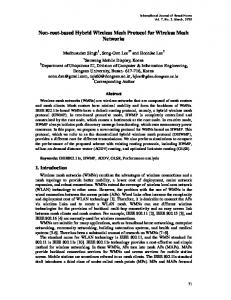
Figure 4.1: Map and topology of the experiment setup.
4.1.1 Basic Setup During experiments the following basic con�guration remained unaltered.
Forwarding
decisions were done based on manually entered static routing table entries using the stock Linux kernel provided functionality. We refrained from using a routing daemon for this simple setup because of the added time prior to the actual experiment. The ARP cache of each router has been populated with appropriate permanent entries so that no ARP requests had to be made during the experiments.
The RTS/CTS mechanism of
IEEE 802.11 has not been utilized. We con�gured the wireless cards to use Orthogonal Frequency Division Multiplex (OFDM) modulation in the ad-hoc mode.
If no further
information is given, we used the default parameters of all mentioned tools.
4.1.2 Network Topology and Environment The whole topology and map of our experimental setup are shown in Figure 4.1.
A
subset of 5 mesh routers placed in one corner of our institute building has been selected. Please note that the walls between the o�ce rooms are very thin and permit radio wave propagation with low loss. The walls to the corridor on the other hand have a very high attenuation factor. DES-Mesh is co-located with the university wide WLAN that uses the same frequency band. This introduces a kind of indeterminism as we cannot shut down the access points. We deem this fact as a real world environment like as no operator of a WMN can control other ones. Coexistence is required, especially as several more WLANs exist in our vicinity. To decrease the interference on our testbed the initial experiments have been executed during the night where the medium is less used and no people are present in the building.
4.1.3 Interference First of all we wanted to have an idea about the interference (respectively the lack of interference) of the used channels. For this, we observed the spectral separation of the orthogonal channels with a spectrum analyzer.
We let one mesh router generate data
that was sent using each of its NICs for a time of 60 s and traced the maximum received signal strength in 12 cm distance to the corresponding antenna.
As it can be seen in
Figure 4.2 the channels are indeed orthogonal and do not interfere with each other. They
4.1. Antenna Separation
29
Figure 4.2: Spectrum of three NICs using orthogonal channels. The pointers mark 2.412, 2.437, and 2.462 GHz (left to right).
are distinguishable from the noise level. This result has of course been expected and is according to the IEEE 802.11 standard.
4.1.4 USB Throughput To get an upper bound for the wireless performance, we measured the USB throughput. Thus, two mesh routers were connected with each other using a host-to-host cable. We used
iperf
to measure the TCP throughput over the USB network interface provided by
the Linux kernel.
For the �rst measurement only the internal hubs of the Alix boards
were used. Afterwards, we connected the powered external hubs used in our routers. A throughput of 110 Mbps has been measured in the �rst and 108 Mbps in the second case as average of 5 runs, each with a time span of 60 s.
That is signi�cant less than
the 161 Mbps we measured beforehand between an Alix and a common desktop PC. Although the 500 MHz AMD Geode LX800 processors seems to be a limiting factor for USB throughput, the achieved values are su�cient for our cause. A net bandwidth of 20 up to 30 Mbps is common for IEEE 802.11g based WLANs.
4.1.5 WLAN Throughput and Delay Two mesh routers were placed within a distance of about 7 m without line of sight (routers 1 and 2 in Figure 4.1). We used �ows generated by
iperf
for 60 s to measure the TCP
throughput. We calculated the average of 5 runs. Delay measurements have been done with
ping
sending ICMP ECHO REQUESTs.
sending rate of 1/s.
Each of these runs took 300 s, with a
The path length was then extended up to 4-hops.
We placed the
routers to form a linear topology where only neighbored nodes could communicate with each other on the link level. The results of this experiment are shown in Figure 4.3. As expected the throughput decreases with the path length and the round trip time increases quite linear with the number of hops.
30
Chapter 4. Practical Experiences & Pitfalls 25
8
Channel 1 Channel 6 Channel 11
20
6
Time [ms]
Throughput [Mbps]
Channel 1 Channel 6 Channel 11
7
15
10
5 4 3 2
5 1
0
0
0
1
2
3
4
0
1
2
Hops
3
4
Hops
(a) Throughput
(b) Round Trip Time (RTT)
Figure 4.3: Single-transceiver throughput and delay.
Channel 1 Channel 6 Channel 11 Sum of Throughput
12
Throughput [Mbps]
10
8
6
4
2
0 0
1
2
3
4
Hops
Figure 4.4: Multi-transceiver throughput over 4 hops.
4.1.6 Multi-Transceiver Comparison We repeated the above measurements with three NICs. Each of them was con�gured to use an orthogonal channel. Again
iperf was utilized - this time generating three �ows in
parallel. If a �ow was generated by the source router using the NIC con�gured to channel
x,
every router receiving these packets did relay them over the same frequency. Packets
therefore traveled from source to destination without switching channels. The results are shown in Figure 4.4. Like in the previous experiment the e�ect of the hop-count on throughput and delay are visible. Comparing the �ows over the three channels we observed some unexpected behavior. In all cases one of the �ows seemed to gain a much higher throughput while the others nearly starved.
Looking at the gained throughput in conjunction with the
path length we noticed an increase of the �ow using channel 11 at hop 2 and the �ow
Channel
Throughput [Mbps]
Mean RTT Deviation [ms]
1
17.830
1.144
6
6.095
1.160
11
9.275
2.900
Table 4.1: Multi-transceiver throughput using 3 disjoint router pairs
4.2. Network to Data Link Layer Mapping
31
using channel 1 at hop 3. This throughput result is comprehensible as every test run is independent of the previous ones. As can be seen, the increase of one �ow always results in an decrease of another one. Even more interesting is the observation that in most cases the sum of all �ows is smaller than the throughput gained using only a single network interface at a time. System resources are left plentiful as the CPU is idling about 80% of the time during the experiments.
Thus, this factor can be ignored as source of the
phenomenon. To get an understanding of the problem, we connected one of the NICs that had reduced throughput per wire to the spectrum analyzer.
Even though the antenna has
been missing the card could still communicate with other ones after placing the particular routers within a distance of 2 m. Starting a single �ow, we could observe activity in the corresponding wave band. Using multiple �ows at the same time, like described above, the card remained silent most of the time. This fact does rebut the assumption that the throughput reduction has been due to increased noise level at the receiver side. At this stage one has to assume a fully transmitter based problem.
Either the Clear Channel
Assessment (CCA) of the NICs, the kernel module implementation, or kernel speci�c scheduling processes are to blame.
To isolate the cause we placed 6 routers within an
o�ce and initiated 3 �ows each using one of the 3 orthogonal channels using 3 disjoint pairs. The source routers were stacked on each other to minimize the antenna distance. We measured 10 samples over a time of 60 s. The results are shown in Table 4.1. As it can be seen the unfairness in throughput is less than in the previous experiment but still present. With this experiment we �nally can exclude kernel speci�c reasons as cause. Antenna separation remains as the source of the problem and seems to be a crucial factor in wireless communication using the IEEE 802.11 standard. Multi-transceiver testbeds have to consider this fact in the planning and evaluation of experiments.
4.2
Network to Data Link Layer Mapping
The ARP is used to resolve network layer addresses to data link layer ones. While being connection-less and o�ering only two types of operation (request and response) pitfalls regarding our testbed do exist nevertheless.
4.2.1 ARP Flux One crucial problem known from network management but rarely mentioned in the domain of multi-homed mesh networks has to be addressed. The ARP Flux symptom arises once hosts have multiple interfaces that are con�gured with di�erent IP addresses of the same subnetwork on a shared medium. problem.
Let us consider the following example to clarify the
Host 1 possesses two network interface cards (IF1 and IF2) that are in an
up state and con�gured with layer 3 addresses IP1 and IP2.
Host 2 is within radio
transmission range and wants to send some data. An ARP request is transmitted and received by Host 1 on both network cards. The ARP implementation processes both of them and replies two times. The problem arises because of this duplication as one of the packets will contain the layer 2 address of IF1 and the other one the address of IF2. This may lead to non-deterministic population of ARP caches [10]. The behavior is known as the �normal� ARP Flux symptom that is usually due to the host owning the layer 3 addresses and not the interfaces. But in our setting we observed a slightly di�erent and more severe problem.
32
Chapter 4. Practical Experiences & Pitfalls
Figure 4.5: ARP Problem Example: The layer 3 to layer 2 resolve process fails because Host 2 answers with the wrong DLL address.
Although the host is also reachable via
IF1 the network address is mapped to IF2. IF1 and IF2 of host 2 do not even have to be con�gured to use the same channel. In this case host 1 does not receive any answers because the reply is sent over a di�erent frequency.
4.2.2 Experienced Symptoms The nodes of our wireless mesh network have been equipped with at least three IEEE 802.11g conform network cards. Network con�guration has been done as discussed and the same Extended Service Set IDenti�er (ESSID) and channel have been set. ARP requests to one of these hosts always resulted in a deterministic cache population. To be more speci�c, although the request has been received by all network interfaces, only one reply was sent. While this might seem slightly better at �rst sight than the expected behavior, it does lead to further problems. Every ARP request to map the three di�erent layer 3 addresses to the corresponding DLL addresses resulted in the same one. The problem is exempli�ed in Figure 4.5. As research revealed the ARP implementation of the Linux kernel is the cause. The route cache and FIB are queried to look-up a route to the originating host. This always succeeds in one case and fails in all others. Usually the �rst interface brought up is used to send a reply containing its layer 2 address. Several problems based on the described �ndings can be noticed in our mesh network testbed:
Multiple IP addresses of foreign hosts are mapped to the same MAC address according to the local ARP cache.
Even the IP address out of a di�erent subnetwork con�gured for the Ethernet interface cards can be reached over the wireless network. One of the wireless NIC's layer 2 addresses is replied.
After setting one wireless NIC to use another channel or ESSID, the corresponding IP addresses can still be addressed by using the original frequency or network identi�er if there remains one NIC with these settings on the host.
Bringing the interface used to answer ARP requests down after another host has stored the false mapping in his cache leads to severe delays. Up to 8 seconds have been observed until a new ARP request is sent and a reply is received successfully.
4.2. Network to Data Link Layer Mapping
33
After bringing an interface down that is not used to answer ARP requests, the corresponding IP address is still reachable by other hosts although no corresponding link exists. This is independent of the ARP cache content of the originating host.
Using broadcast
ICMP ECHO REQUESTs only one reply will be received even if neigh-
bored hosts use multiple NICs. Based on these observations several conclusions can be made regarding experiments and the validity of their results.
4.2.3 Impact on Experiments As a large part of our research is and will be based on data link and network layer protocols the impact on experiments has to be discussed. The e�ect how ARP is handled might have a strong in�uence on routing protocols. From the network layer point of view we normally assume when an IP address of a neighbored host can be reached, a link has to exist. As we discussed this cannot be deduced. Evaluations of measured data gained from network protocol experiments always have to consider the underlying links otherwise false interpretations are possible. Let us consider a simple example: Packets destined for IP1 mapped to IF1 could be received over IF2 additional by the ones destined to address IP2. If we assume both interfaces use di�erent channels, media congestion of one of the channels could arise while the other one idles. Depending on how the transferred bytes per time unit are measured, for example per host or interface, di�erent conclusions may be drawn from evaluation results. Misinterpretations therefore have to be avoided. Limited data rates might not be ascribed to network congestion but rather unexpected interface selection. As mentioned in the previous section broadcast
ICMP ECHO REQUESTs
cannot be used
to detect all mesh routers' layer 3 addresses. Routing algorithms relying on this mechanism will deviate from their expected behavior and/or experience a drop in performance. The severity of these e�ects and the underlying problem have to be examined in conjunction with the objectives of experiments. Depending on the set goals and expected setting the current state can be either tolerable or problematic.
To change the kernel
protocol stack behavior during runtime we discuss solutions in the following sections after discussing some possible reasons for this behavior.
4.2.4 Operation System Speci�c Design Reasons The behavior described in Section 4.2.2 has been observed running a Linux kernel of version 2.6.22. It can be assumed that the operation system manages layer 3 addresses as associated to the host and not to the interfaces. While this has the mentioned disadvantages, there are some reasonable motives to choose such an implementation.
First of all, in common networks each interface connects a host to a di�erent subnetwork. Multihomed settings are usually used only because of loadbalancing reasons or in the case of virtual hosts with virtual interfaces mapped to a shared physical one. Some solutions have been proposed for these scenarios. We discuss them in Section 4.2.5.
34
Chapter 4. Practical Experiences & Pitfalls
By assigning network layer addresses to hosts a strict disjunction attributed to a layered communication model is achieved. Forwarding is a layer 3 task. The decisions made should be independent of any underlying requirements like unambiguous DLL to network layer mappings such as in our setting.
Reliability seems to have been one of the incentive motives. By using this approach, hosts are reachable over any device.
In real wold settings it is more of concern
that communication is possible than to deduce that all packets destined to an IP addressed have been received only over the associated interface.
Shorter routes might also be established. In our testbed a node could communicate with another one by using a probably longer route than usual.
This case might
arise, for example if we cannot use the channel that the packet should have used originally and therefore would need to be relayed over intermediate routers.
If a
link on another channel to the destination does exist, this one could be used instead even if the particular routing protocol does not consider this alternative because of the ARP resolution. Please note that such an approach needs ARP requests to be implicitly broadcasted over all interfaces without regard of the subnet-mask. As discussed our �ndings are based on Linux. Other operating systems like BSD or MS Windows kernels handle the mapping di�erently.
4.2.5 Solution Approaches For a maximum of �exibility we need a solution customizable at runtime. The following parameters shall be con�gurable and switched on and o� in demand: 1. Hosts shall answer ARP requests when they are received over the NIC that has the target IP address associated
or without regard of the interface if the host owns the
address. 2. ARP replies shall be sent via the interface owning the target address of the ARP request
or the kernel may select the most appropriate output device.
Based on the selected settings a host will either receive ARP replies in most cases or only if the request is sent over an interface using the same wireless channel and ESSID as the target device.
Cloned MAC Address:
Assigning each local interface the same layer 2 address
solves the problem of non-deterministic ARP cache population (ARP Flux) by sacri�cing distinguishability. It is obvious we need a more advanced solution to preserve this information.
Ignore and Hidden Flags: modes for each device.
The
arp ignore
sysctl
enables us to de�ne several
The default con�guration for most Linux distributions is
set to reply for any local target IP address con�gured on any interface. Optionally replies are sent only if the target IP address is con�gured on the incoming interface. An even more restrictive setting exists that requires the sender address to be part of the same subnetwork. Using the �ag works as expected and solves the problem of ICMP echo requests being answered for target IP addresses even if they belong to another subnet. In
4.3. Network Booting
35
a setting with two wireless NICs on the destination host con�gured with two IP addresses out of the same subnetwork a severe issue remains nevertheless. each received ARP request
arp process()
address (a local one in this case) by calling
For
tries to �nd a route to the target IP
ip route input()
to query the route
cache. On cache misses the route cache respectively the FIB are queried in the next step (ip
route input slow()).
Unfortunately, this is successful if the request is
received by the �rst interface and otherwise fails. Therefore, no ARP reply is sent if a request is destined to the IP address belonging to the second interface while the ignore �ag is set. The notion of ��rst� and �second� interface has to be understood in this context as ��rst or second one brought up�, respectively the up-time determines the order. By applying an external patch the to
arp hidden sysctl
is provided. It is very similar
arp ignore and because of the same reasons mentioned above this approach does
not meet our requirements. Additionally, we would like to avoid kernel patches.
Filter Flag:
Setting this boolean value (arp
ignore)
to true allows ARP request
to be answered over the particular interface. The �nal decision whether the interface is used depends on the set routes. Source based routing is needed which disquali�es this solution for our problem as not all routing protocols will provide the needed information.
Announce Flag:
The
arp announce
�ag lets us de�ne restriction levels for an-
nouncing the local source IP address from IP packets in ARP requests sent on the interface. None of the discussed approaches alone does solve our problem.
Problem Solution and Interface Con�guration arp ignore to reply only to requests for IP addresses con�gured to the particular interface and switching spoo�ng detection o� (rp filter) leads to the desired behavior
Setting
but does not free us of all problems.
Eventually, each of our three WLAN cards per
router was con�gured to an individual subnet. With this solution it is left to each routing protocol to announce whether neighbored routers should be able to communicate crossing the borders of the subnets and with that use di�erent channels on a path between source and destination.
Neighborhood information about the DLL is only promoted between
adjacent entities via ARP packets if they are using the same channel. With these simple system control and network settings our testbed can be used for evaluation with the desired �exibility. It will be an interesting task to measure the signi�cance of several di�erent settings in experiments.
4.3
Network Booting
As discussed in Section 2.2 our mesh routers have no persistent memory, like a hard disk or �ash memory, and therefore boot over Ethernet. In some cases after cold restarts the PXE boot ROM reports error
PXE-E61.
The media test failed although a cable is connected
and thus the boot process halts. We tested multiple di�erent cables but experienced the same symptom. In some rare cases, like power failures, the mesh routers therefore might
36
Chapter 4. Practical Experiences & Pitfalls
need on-site maintenance to continue booting.
The cause of this problem seems to be
related to the BIOS that we currently use in the up-to-date version 0.99.
The overall
start up proceeds too fast so that the Ethernet NIC has no time to detect the link. To �x this problem we enabled the
wait for hdd option in the BIOS. This gives hard
disks more time to spin up before they get probed and accessed.
The delay of several
seconds resolves our problem even though the option was intended for another cause.
4.4
Time Synchronization
The Network Time Protocol (NTP) is used to synchronize the time base of our mesh routers with the mesh server and provides the timebase. The mesh server itself synchronizes against the university time server:
time.fu-berlin.de.
A severe problem arises if NTP is used along with NFS. The Alix2c2 mainboard is not equipped with a battery to store the system time between reboots. Customized boards with battery are available on request only for an additional charge.
When the routers
are switched on, the root �le system is mounted over the network after an IP address has been acquired via DHCP for the primary ethernet network interface.
During the
System V initialization process the same network interface is brought up again but this time synchronization is done as it is a standard feature of the Debian distribution if the
ntp-date package is installed.
Suddenly the clock's time jumps several years to the future.
DHCP clients get confused by this change because their leases seem to have expired a long time ago. The network interface is brought down to broadcast a
DHCPDISCOVER
and
to acquire a new IP address. This is a fatal action for the mounted root �le system. The result is a frozen and unresponsive system. As preliminary �x to solve the problem the interface deactivation has been removed from DHCP client scripts.
4.5
Universal Serial Bus
After doing the initial measurements (see Section 4.1) we experienced problems with the hardware after about 12 to 24h of up-time. The problem consists of one of our WLAN NICs being not accessible anymore because the driver is unable to access the command registers on the WLAN adapter. In debug mode the following error message is printed multiple times per second and while the adapter is rendered useless.
rt2x00usb_vendor_request: Error - Vendor Request 0x07 failed for offset 0x3090 with error -71. Once this behavior occurs, the card has to be unplugged and inserted again, forcing a new initialization of the USB device. Optionally the mesh router can be rebooted to �x this issue. Changing the state of the interface with
ifdown
and
problem. The possible points of failure are:
Firmware image or OS speci�c driver of the WLAN card
OS speci�c settings and USB drivers
USB hub or extension cables
ifup
does not solve the
4.5. Universal Serial Bus
37
To eliminate another possible point of failure, we disabled the dynamic power management of all USB devices in the Linux kernel by setting ingly.
CONFIG_USB_SUSPEND
accord-
Since many USB devices do not support power management as speci�ed by the
corresponding standard, resuming a suspended device can make the device stop working entirely. The rt2x00 driver used in the WLAN adapters supports suspend and resume, but to �nd the cause of the problem we entirely disabled this function. Various tests indicated that the USB hub is involved in this problem or even the main cause. When we connect two WLAN adapters directly or via extension cables to the USB ports of the Alix2c2 mainboard, the problem does not occur and the WLAN adapters run for several days without any kind of error. To pin down the point of failure we ran various tests with modi�cations to the utilized USB hub infrastructure. We eventually suspected the power supply of the USB hub as the point of failure since measurements of the power consumption showed, that while transmitting, a wireless network adapter came close to the 500 mA available on each USB port. Although our USB hub is externally powered and the available 2300 mA at 5V should be su�cient for the three NICs, there are many reports about poor USB hardware that does not fully meet the USB 2.0 requirements. This suspicion was also backed up by experiments with less than three NICs attached to the USB hub which showed no errors.
We then split the three NICs up and used
two of our USB hubs, each plugged into one of the mainboards USB ports. con�guration the mesh router ran also error-free for several days.
With this
In the next step we
replaced the USB hub with di�erent devices by di�erent vendors. Replacing our hub with a random no name one resulted in the same error. Experiments with a Equip 4-Port USB hub seems to have solved the problem since all NICs are still running after several days. Further tests will be carried out using a D-LINK DUB-H4 USB hub.
38
Chapter 4. Practical Experiences & Pitfalls
CHAPTER 5
Conclusion In this publication we continued our report about the work-in-progress DES testbed of 100 routers deployed at the
Freie Universität Berlin.
We discussed the software archi-
tecture and gave an introduction to the network protocol stack of the Linux kernel. Our �rst experiences with a pilot network setup including the encountered problems have been described and viable solutions proposed. The practical experiences and pitfalls in combination with the technical aspects discussed in this writing are signi�cant for all mesh testbed installations. These challenges have to be taken care of.If they are ignored, experiments can result in erroneous measurements and inaccurate data. With the hybrid DES testbed the CST work group has a powerful tool for wireless network related research and education. After �nishing the �rst stage of setup the DES testbed will be used to do long-term experiments.
39
40
Chapter 5. Conclusion
Bibliography [1] M. Güne³, B. Blywis, F. Juraschek, and P. Schmidt, �Concept and design of the hybrid distributed embedded systems testbed,� Freie Universität Berlin, Tech. Rep., 2008. [2] �dnsmasq.� [Online]. Available: http://thekelleys.org.uk/dnsmasq/doc.html [3] �The syslinux project.� [Online]. Available:
http://syslinux.zytor.com/wiki/index.
php/The_SYSLINUX_Project [4] K. Wehrle, F. Pahlke, H. Ritter, D. Muller, and M. Bechler,
tecture.
[5] J.
Linux Network Archi-
Prentice Hall, April 2004.
Salim,
H.
Khosravi,
A.
Kleen,
and
A.
Kuznetsov,
� Linux
Netlink
as
an
IP Services Protocol,� RFC 3549 (Informational), Jul. 2003. [Online]. Available: http://www.ietf.org/rfc/rfc3549.txt [6] �Quagga routing software suite.� [Online]. Available: http://www.quagga.net/ [7] �Gnu zebra.� [Online]. Available: http://www.zebra.org/ [8] V. Kawadia, Y. Zhang, and B. Gupta, �System services for implementing ad-hoc routing protocols,� in
Proc. International Conference on Parallel Processing Workshops,
Y. Zhang, Ed., 2002, pp. 135�142. [9] E. Kohler, R. Morris, B. Chen, J. Jannotti, and M. F. Kaashoek, �The click modular router,�
ACM Transactions on Computer Systems,
vol. 18,
no. 3,
pp. 263�297,
August 2000. [Online]. Available: http://www.read.cs.ucla.edu/click/publications [10] M. A. Brown,
Guide to IP Layer Network Administration with Linux.
Documentation Project (TLDP), 2003.
41
The Linux