Oct 21, 2004 ... thesis statement, Section 2, has been rewritten and the expected con- tributions
... which are the prerequisites for a hardware implementation.
Practical Photon Mapping in Hardware A Dissertation Proposal∗
t
Josh Steinhurst Department of Computer Science University of North Carolina at Chapel Hill
af
October 21, 2004
Contents
1 Modifications
2 Thesis Statement
3 Expected Contributions
Deliverables . . . . . . . . . .
2 7 Importance Sampling 7.1 Sampling the BRDF . . . . . 4 7.2 Sampling incident radiance . 7.3 Combining multiple approaches 4 7.4 Uses beyond photon mapping 7.5 Deliverables . . . . . . . . . . 5 6 8 Computational Requirements 8.1 Deliverables . . . . . . . . . . 7 8 10 9 An Architecture 9.1 Target implementation . . . . 11 9.2 Initial thoughts . . . . . . . . 12 9.3 Irradiance caching . . . . . . 12 9.4 Deliverables . . . . . . . . . . 12 13 10 Schedule 14 16 11 Proposed Oral Exam Topics 18 18 References
Dr
4 Introduction 4.1 Targeted Scenes . . . . . . . .
6.5
5 Background 5.1 Photon mapping . . . . . . . 5.2 Acceleration of ray casting . . 5.3 Projected hardware capabilities 6 Bandwidth reduction 6.1 Required bandwidth . . . . . 6.2 Photon map data structure . 6.3 Query Reordering . . . . . . . 6.3.1 Generative reordering 6.3.2 Deferred reordering . . 6.3.3 Comparison . . . . . . 6.4 Irradiance caching . . . . . . ∗
19
20 22 22 23 23 23 24 26 27 27 27 29 30 32 32 32
This second version is based on the feedback received from the committee on October 6, 2004. Please see page 2 for a cross-referenced list of the changes.
1
1
Modifications From The First Version
I have modified my proposal to address the feedback that I received from my committee. For your convenience the changes are listed below. Although I have not changed the essential substance of my proposal I have clarified my expected contributions and how I intend to demonstrate them.
af
t
Overall Vision: I have strengthened the presentation of my vision. The thesis statement, Section 2, has been rewritten and the expected contributions, Section 3, are more specific and definite. The evaluation criteria, Sections 6.5, 7.5 and 9.4, have been renamed as ‘deliverables’ and more clearly transition from a general discussion of the issues to my specific plan of action.
Dr
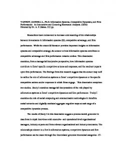
Test Scenes: I now provide a clearer description of the kind of scenes I will target in the Introduction, Section 4. I state that I will have three kinds of scenes and describe the characteristics of each scene. I explain why I need each characteristic. Figure 1 uses an image of Rui Basto’s version of the Brook’s House as an example scene. For each scene I will create a fixed camera path, this path will be used during simulation to investigate how variable the results are. The thesis statement, Section 2, qualifies the word scene with nontrivial. I have switched from the term real time rendering to interactive rendering, meaning 10 to 60 frames per second.
Background: Mention is made of how caustics are rendered using a separate photon map and a direct visualization. I now provide a table of the “magic” numbers in photon mapping. The likelihood of point to point serial chip communications was upgraded from possible to expected. Query Reordering: In Section 6 I now emphasize the generative reordering since I expect it to dominate when implementation costs are considered. I will explore some additional reorderings in my dissertation. These include the Morton order and an interesting idea that Jan introduced to me from n-body literature. The deliverables, Section 6.5, now includes a chart to show the cost of reordering in terms of storage and computation. The intention is to use this in conjunction with the reordering benefit chart to determine the proper algorithm for use in my or any other architecture. 2
Irradiance Caching: I no longer propose designing irradiance caching into the architecture because I do not believe that it is an effective technique for the target scenes, Section 6.4. That said, I do still plan to study it this fall and determine what interactions it has with query reordering, Section 6.5. It is a technique that must be addressed by any research into photon mapping. I will explain why the implementation cost outweighs the benefit, at least for the scenes we are interested in.
t
Importance sampling: I discuss in Section 7 the impact the various surface properties have on importance sampling. Instead of hardware amenability, I now talk of designing and evaluating an algorithm that is resource, computation and internal state, constrained, Section 7.5, which are the prerequisites for a hardware implementation.
af
Computation: I have added a rough sensitivity analysis, this is something that will become much more precise in the dissertation.
Architecture: The biggest change to the architecture, Section 9, is that I clearly define my deliverables. The possible levels of simulation are described and I state how I will simulate each component. I have removed irradiance caching from my description of the planned architecture. Instead I provide commentary and an extra diagram showing how it could be included. I will measure the implementation cost and show that it outweighs the benefit.
Dr
I also removed eye ray generation from the ray caster unit to make the figures clearer. The computation of shadow rays for direct illumination is now described, as is the direct visualization of a separate caustic photon map. The dissertation will discuss possible target implementation technologies, ASIC, FPGA, CPU and cluster, and justify a choice. The choice will determine what constitutes reasonable bandwidths, internal storage, and computational power. I expect to choose a PCI-Express with 1 to 4 ASIC chips. I will also address the issue of deadlock.
Minor changes: Several minor changes were suggested, especially in the Introduction, and I adopted most of them. Some were grammatical while others correctly noted a few overly broad statements. PhD Plan of Study: This section was removed from the proposal because the committee has approved the plan and it was submitted. 3
2
Thesis Statement
Complex scenes can be rendered with the photon map algorithm at interactive rates by an architecture that 1) reduces I/O complexity with memory coherent ray casting and photon gathering; 2) implements resource constrained importance sampling; and 3) can be feasible implemented in the near future.
Expected Contributions
t
3
I expect to make a number of significant contributions that advance the state of the art in photon mapping and demonstrate that a system could be built to visualize photon maps at interactive rates:
af
Low bandwidth photon gathers using reordering: I will show that by reordering the computation of the k NN queries required for photon gathers that I can dramatically reduce the required bandwidth compared to the naive algorithm. Resource constrained importance sampling: I will demonstrate an algorithm for importance sampling that uses the information in both the BRDF and the estimated incident radiance from a photon map that is constrained by limited bandwidth, computation and state. In addition to photon mapping this unit will be beneficial in ray tracing systems.
Dr
A complete photon mapping architecture: I will present a complete architecture capable of rendering complex scenes using the photon mapping algorithm. The target implementation technology is a PCIExpress board with one to four custom ASIC chips.
Bandwidth reduction synergy: I will demonstrate the positive interaction of photon gather reordering, ray casting, and importance sampling. A related contribution that I do not intend to pursue but that may come up, especially if any of the above have fundamental problems:
Dynamic scenes: I may investigate updating a dynamic photon map in parallel to a dynamic scene. Both the generation and update of the photon map data structure would be interesting areas to research.
4
4
Introduction
Dr
af
t
Modelling the interaction of light and the objects in a scene is the essence of realistic image synthesis. Local illumination models assume that light is emitted by a source, reflects off a single surface and is captured on the viewing plane forming an image. Although sophisticated physically-based models of reflection are now in use, the framework in which they are used is relatively simple. The illumination at any point in the scene is completely independent of the rest of the scene. This separability enables a high degree of parallelism that is well exploited by modern graphics hardware. Realistic illumination at a single point however is dependent on the entire scene. There may be shadows, light may bounce indirectly off of multiple objects, there may be highly specular mirrors, caustics may form, etc. These effects can be painstakingly added one by one to an image generated with local illumination models using single purpose rendering algorithms such as shadow volumes [Hei91], environment maps [BN76, Gre86], pre-computed radiosity textures [CW93], or even a highly specific glittering gem effect [Gos04]. These algorithms are hard to combine or generalize and fail to capture essential parts of the underlying physics: the shadow maps may cause aliasing; environment maps are incorrect unless computed at the exact center of a purely reflective sphere; the sparkling gem effect may fail when submerged in water; the pre-computed radiosity textures have to be recomputed if the scene changes significantly; and the combination of these effects requires impractical planning and is sometimes impossible. Generic global illumination models, on the other hand, create the effects directly by simulating, with varying accuracy, the physics of light transport between objects in a scene. The very benefit of global illumination, the correct simulation of multiple interactions of light with the scene, also explains why generic global illumination algorithms are so rarely used in interactive applications. The illumination at every point in the scene depends not only on the emitters but also recursively on every other visible point in the scene. Z Lr (x, ~ω ) = fr (x, ω~ 0 , ω ~ )Li (x, ω~ 0 )(ω~ 0 • ~n) (1) Ω
This is perhaps best demonstrated by the rendering equation, Equation 1, put forth by Kajiya [Kaj86]. The reflected radiance from point x in the direction ω, Lr (x, ω ~ ), is the integral over the hemisphere of the incident 5
Dr
af
t
radiance, fr (x, ω~ 0 , ω ~ ), and the BRDF evaluated at point x for the incoming direction of ω ~ and the outgoing direction of ω~ 0 . The incident radiance is calculated recursively until a stoping criterion is reached. The effect of this recursive explosion of computation is that global illumination algorithms are inherently computation and bandwidth intensive. There are several global illumination algorithms that capture some portion of the expressibility of the rendering equation: path tracing (Whittedstyle ray tracing [Whi80], stochastic ray tracing [CPC84], bi-directional ray tracing [LW93]), radiosity [GTGB84], and more recently photon mapping. Radiosity is restricted to diffuse surfaces. Whitted-style ray tracing is unable to handle glossy surfaces, caustics, and several other desired effects. The more advanced path tracing algorithms, excluding bi-directional ray tracing, can have a very hard time handling caustics and some other effects. Bi-directional ray tracing can be thought of as related to photon mapping for example but it has some problems, mirrored images of caustics are difficult and it is very inefficient if the observer is a small part of the scene. Photon mapping [Jen96, Jen01] is a popular and robust global illumination algorithm. It can reproduce a wide range of visual effects including indirect illumination, color bleeding, and caustics on complex diffuse, glossy and specular surfaces represented using arbitrary geometric primitives. It works well in scenes where the light has a hard time reaching the scene, i.e. a room light by a keyhole. Recent natural extensions allow photon mapping to handle even complex effects such as mirages and complicated water environments[GAMS04]. For these reasons I wish to develop techniques and an architecture capable of rendering images interactively using the photon mapping algorithm.
4.1
Targeted Scenes
I am interested in nontrivial scenes, each of which has some of these features: • Medium geometric complexity: 10,000 to 100,000 triangles. This will provide a realistic load to the ray casting unit. • Varying surface reflectance properties: diffuse, glossy and specular. This will be important to fully test the combined importance sampler. • A camera position that views less then half of the scene. This ex6
poses one of the weaknesses of any bi-directional global illumination algorithm such as photon mapping. • Medium size area lights. This will make sure that the system for handling direct illumination is capable of sufficient shadow rays.
t
• Camera path. I will construct a fixed camera path for each scene. This will be used by the simulations to examine performance variance and to generate results for a sequence of frames as opposed to a single frame.
af
These requirements will result in a fair evaluation of photon mapping, irradiance caching, query reordering, and importance sampling thereby making the architecture simulation representative of the desired workload. I will have at least three scenes that meet these criteria while sampling the space of potential uses:
Architectural walkthrough A multiple room model suitable for walkthroughs. The Brooks House model developed here at UNC-CH with the glossy and specular additions made by Rui Bastos [BHWL99] is a good example. The geometry is of fairly simple although a large area is modeled. The illumination however is complex.
Dr
First person shooter A scene found in a commercial first person shooter such as Quake. This scene would have interesting illumination of some complicated objects in a fairly simple environment.
Global illumination demonstration There are certain global illumination phenomena for which the photon map algorithm is particularly good such as caustics and color bleeding that can be subtle. This scene would exaggerate these effects with camera position and scene composition to closely examine the effects. The Cornell box, Jensen’s cognac glass, and the SaarLand headlight models are examples of such scenes.
5
Background
In this section I provide an overview of photon mapping, declare some definitions, review some previous work in ray casting acceleration, and provide a short projection of future hardware capabilities. A reader that is well versed in these matters may wish to skim this section. 7
t af
Figure 1: The Brook’s House model developed here at UNC-CH as extended by Rui Bastos is a good example of an architectural scene that meets our criteria [BHWL99].
5.1
Photon mapping
Dr
Photon mapping is a two-step algorithm. The first step, called photon tracing, shoots photons outward from the light sources into the environment. These photons are probabilistically reflected, refracted and finally absorbed at non-specular surfaces. When a photon is absorbed, its location, power, and incident direction are stored in a view-independent photon map. For scenes involving indirect illumination, this typically involves shooting hundreds of thousands of photons [Jen01]. A photon map can be generated once and reused for multiple viewpoints as long as the scene does not change. The second step of the algorithm is visualize the photon map into a rendered image. The viewpoint is fixed and an eye ray, ω ~ , is cast into the scene for each pixel (u, v) of the final image (or multiple rays per pixel if antialiasing is desired). At the point x where the eye ray intersects the scene geometry the direct illumination is computed and additional rays are cast to sample any specular reflection. The indirect diffuse illumination, L, is computed from the data in the photon map. Jensen describes two photon map visualizations that compute L differently, direct and final gather. I have denoted these terms as L≈ and 8
w
wp
t
p x
af
Figure 2: L≈ (x, ~ω ) calculated using a photon gather.
Dr
L= , respectively. For the direct visualization, illustrated in Figure 2, a k Nearest-Neighbor (k NN) search is conducted in a small neighborhood around the point x using the photon map. Reasonable values for k are 100 or more [Jen01]. Every photon in the photon map has a power 4Φp and direction ω~p . If a photon p is selected by the k NN search, these values are used with the surface reflectance properties (BRDF) fr to compute the contribution to the reflected radiance L≈ (x, ~ω ). The sum of the contributions is computed in Equation 2 and is commonly referred to as a photon gather. The photon gather is thus an estimate of Equation 1.
≈
L (x, ~ω ) =
k X
fr (x, ω~p , ω ~)
p=1
4Φp (x, ω~p ) 4A
N 1 X L (x, ~ω ) = fr (x, ω~i , ω ~ )L≈ (yi , ω~i )(n~x • w) ~ N i=1 =
(2) (3)
Final gather visualization, shown in Figure 3, estimates the rendering equations using a Monte Carlo integration at point x. The hemisphere centered at x and oriented along the surface normal is sampled and N rays ω~i are cast out into the scene. Ray ω~i intersects some object in the scene at point yi . At each point yi a photon gather is performed by calculating L≈ (yi , ω~i ). These results are then weighted by the BRDF of the surface at x to get the 9
yi
wi
x
t
w
af
Figure 3: L= (x, ~ω ) calculated using Monte Carlo integration with many evaluations of L≈ (yi , ω~i ).
Dr
indirect diffuse illumination at point x. This method is shown in Equation 3 as the weighted sum of N photon gathers. Photon mapping is a biased yet consistent method for estimating radiance [Jen04]. The result will converge as more photons are gathered, but is not guaranteed to converge to the correct result. The direct visualization can exhibit visual artifacts unless an large number of photons are used [Jen01]. I have chosen to base my work on the higher-quality final gather visualization. An exception to the final gather decision are caustics. It is generally agreed that the best way to handle caustics is to create a second photon map where photons must bounce off at least one specular surface before they are absorbed [Jen01]. This second photon map is usually constructed with fewer photons and is always visualized directly. There has been limited prior research regarding photon mapping in hardware. Purcell implemented a version of the direct visualization with a very basic data structure on commodity graphic processors [PDC+ 03]. Hachisuka used commodity graphic processors to do final gather [Hac04]. To the best of my knowledge no one has designed custom hardware for photon mapping or k NN queries in general.
5.2
Acceleration of ray casting
Ray tracing is one of the embarrassingly parallel computation tasks. Ray tracing acceleration research can be grouped in a few broad categories: 1) 10
Term Number of photons in photon map k, the number of photons that we try to find for each gather Final gather rays used to estimate the incident radiance Number caustic photon gathers per eye ray S World space maximum search radius for photons
Reasonable value 1,000,000 100 100 1 N/A
t
Table 1: A list of interesting photon mapping constants
Dr
af
hierarchal or space division data structures for scene geometry; 2) dividing the work across multiple processors; 3) processing bundles of coherent rays together; and 4) reordering ray generation to promote coherency. Categories 3 and 4 are related, but otherwise the techniques are independent. There has been a great deal of research into performing interactive ray tracing on PC clusters and/or specialized hardware. Additionally there are a number of cache coherent techniques that reduce the actual bandwidth consumed by ray casting. Pharr [PH96] used a space-filling curve on the screen to generate the eye rays in an order that increased the effectiveness of a geometry cache. Several researchers [RJ96, PKGH97, SWS02, DK00] have described different ways of scheduling rays after they are generated to maximize cache use. Kedem developed a machine for ray casting CSG [KE84]. I do not plan to seriously innovate in the ray casting arena. I will adopt proven ray casting hardware into my architecture. I do expect, however, to see modestly improved efficiency of the ray casting hardware when the other techniques are applied because they will increase the coherence of the rays cast.
5.3
Projected hardware capabilities
I expect that current trends in semiconductor development will continue as laid out by an industry trade group for the next four years [ITR03]. Specifically, the ASIC Metal 1 12 pitch size will fall by approximately 30%. This will allow for a near doubling of transistors per chip from 1 billion to 2 billion. Chip size and signal I/O pad count are, however, expected to remain constant. I expect only a moderate improvement in off-chip signalling speed per pad except for the jump to point to point serial communications [Pou04].
11
6
Bandwidth reduction
6.1
Required bandwidth
af
t
In the absence of irradiance caching, Section 6.4, and importance sampling, Section 7, it is not uncommon to perform at least 100 gathers per eye ray if final gather visualization is used. If each photon requires 20 bytes of storage [Jen01], the minimum raw bandwidth for k = 100 and a 512 × 512 image is 512×512×100×100×20B = 50GB. As high as this figure is, it is only obtainable if you have a k NN query function that that examines exactly the photons that are selected, an oracle. By instrumenting a a software photon mapper for a specific scene I found that 122GB of raw memory traffic is generated. I have observed that as a rule of thumb, for data sets of the size and nature that we are interested in, that a k NN search in a kd -tree photon map data structure examines roughly twice as many photons as are selected. The memory system is therefore presented with 100GB of memory traffic for the gathers alone in this example image. Any reasonable architecture will of course use a memory cache. The rest of this section examines the interaction of data structures and algorithms on the cache performance.
6.2
Photon map data structure
Dr
Jensen championed using a 3D data structure to hold the photon map. Some benefits of a decoupled 3D data structure are: 1) procedural and parameterized geometry may be used; and 2) each piece of geometry need not have its own data structure, especially useful when a scene is modelled with polygons of widely varying size [Jen01]. Two significant drawbacks are: 1) a separate data structure must be maintained; and 2) care must be taken when performing a photon gather to not use photons that hit on a different surface. Jensen suggests using a kd -tree to store the photon map because it has algorithmic optimal properties for k NN searches [Ben75]. In previous research I have compared several data structures for this application to evaluate their cache performance. I found that under certain conditions there are data structures that are more cache friendly. However when queries are reordered as described in Section 6.3, the differences are either negligible or even negative compared to the kd -tree. I found that reordering the queries was a much more significant benefit then changing the data structure. The two most significant drawbacks of the kd -tree for a hardware implementation are that 12
a stack must be maintained and that multiple rounds of memory accesses are required leading to high latency [MM02]. I expect that my architecture will use the kd -tree and both hide the latency and improve cache performance by processing many queries simultaneously.
6.3
Query Reordering
Dr
af
t
Caches reduce memory traffic by exploiting spatial locality in the memory request stream. For any reasonable data structure each k NN search will examine a small portion of the photon map data structure. A cache will be helpful only if there is a good chance that a k NN search takes place in the same region of the photon map as the previously computed one. The key insight of query reordering is that there exists a large amount of coherence amongst all of the k NN search queries even with final gather visualization due to the spatial locality of the query locations, yi in Figure 3. Standard implementations of photon mapping are not structured to exploit this coherence, which results in poor cache behavior. Recognizing the linearity of Equation 3 we can reorder the k NN searches into any order that is convenient without changing the rendered image. There are two general approaches to query reordering. The first is a set of generative schemes, which modify the order in which searches are generated. The second approach, which I call deferred reordering, is to generate the list of k NN search locations, called Y , and reorder them, Y 0 , to maximize coherence before performing the searches. Both of these approaches may require extra computation and storage, which must be balanced against the substantial gains from cache coherent behavior. My goal is to find the best order, in terms of bandwidth reduction, while staying within the constraints of a reasonable hardware implementation. While describing the reordering techniques I will present some of the results that we presented in our Graphics Hardware 2004 submission. In Section 6.1, we calculated that for our test scene a bandwidth of 50GB is required with an oracle style k NN query that only touches exactly those photons returned or 122GB using the kd -tree data structure. As shown in Figure 4 we found that reordering the k NN queries can dramatically reduce memory bandwidth. I am currently reimplementing the reordering memory hierarchy simulation using the pbrt framework [PH04]. This is to provide a more robust
13
3
10
2
1
10
0
Naive Tiled Hilbert Tiled Dir Bin Tiled Hash
af
10
t
Bandwidth (GB)
10
−1
10
1
2
4
8 16 Tile Size
32
64
128
Dr
Figure 4: The Hilbert curve reordering continues to improve as tile size increases, while the practical reordering algorithms achieve maximum performance at either 16 × 16 or 32 × 32 size tiles. The space between the top and bottom curves indicates the range of improvement possible by reordering searches. For example, in the case of 16 × 16 tiles the range is 211GB to 11GB. (kd -tree data structure with a 128KB cache and 128B cache lines.) framework in which to simulate irradiance caching, importance sampling and the other techniques that I will be studying. 6.3.1
Generative reordering
The first set of techniques for increasing the temporal locality of k NN searches consists of generating the search locations in a coherent order. Naive ordering. In the naive algorithm each pixel is processed in row order. All the secondary rays are shot and generate queries. Each the k NN 14
search is processed as soon as it is generated and the result is stored directly at the destination pixel. I found that naive ordering required 211GB of traffic to main memory from the cache. No additional storage or computation is required for this ordering, each final gather can be performed as they are ready.
af
t
Tiled reordering. In most scenes the eye rays from neighboring pixels will intersect the scene at points x in close proximity to each other [WSBW01]. There will therefore be a high coherence among the origins of the rays cast during the Monte Carlo integration. To exploit this coherence, I break the screen into tiles and create a list of all the query sites generated by the pixels in that tile, Y . Each individual tile in then processed in row order. A similar technique is commonly used on current graphics rasterization hardware to improve texture memory locality [MMG+ 98]. A slight enhancement is to process the rows in alternating directions. The drawback to the tiled approach is that even though the origins x of the rays used by the Monte Carlo integration are similar, the directions ω~i remain random. In my experiments, which consisted of a relatively open room, the resulting search locations yi are scattered throughout the scene and this ordering performs equal to or slightly worse then naive. No additional storage is required and the extra computation is negligible.
Dr
Tiled direction-binning reordering. Considering a subset of the secondary rays that have similar directions, ω~i , it is reasonable to expect the gather sites yi to be in close proximity to each other [WSBW01]. The tiled algorithm can be improved by passing over each tile multiple times. On each pass only secondary rays ω~i that fall within a specified interval of directions are generated. This algorithm incurs some overhead; each pass requires the results of the eye ray intersection, x, and the direction, ω ~ . This can either be recalculated by re-casting the view ray, or stored from the first pass. My experiments use 16×16 direction bins and depending on tile size found bandwidths to main memory as low as 36GB. This ordering requires storing the intersection, ray direction, and BRDF properties of each final gather in the tile. I hypothesize that tiled direction-binning will work even better when importance sampling, Section 7, is used in the Monte Carlo integration. This
15
is because the search locations yi will be clustered in smaller areas of the hemisphere corresponding to the directions of strongest incident radiance. 6.3.2
Deferred reordering
af
t
The structure of Equation 3 showed that the photon gathers, and their associated k NN searches, can be performed in any convenient order. The second set of techniques for improving the temporal locality of the photon gathers consists of generating a list Y of the search locations with one of the generative techniques. The elements yi ∈ Y are then reordered into Y 0 before processing. Decoupling the search location generation from the processing introduces some overhead. In addition to any extra computation that may need to take place, the search location, the RGB weight, and the destination pixel must be stored. This is a lot of storage because there are on the order of 100 queries for each pixel or 26 million for a 512x512 image.
Dr
Hilbert curve reordering. The Hilbert space-filling curve is often used to produce a linear mapping of a multidimensional space [FR89]. A desirable property of Hilbert curves is that the locality between objects in the multidimensional space is preserved in the linear ordering [MJFS96]. We use the three-dimensional Hilbert curve to reorder the entire set of k NN searches, Y 0 = Hilbert(Y ). If the entire screen is processed through the Hilbert reordering the savings are enormous, down to 15MB. The computation is however significant as it is a form of sorting. I use an unpublished algorithm by Jack Snoyeink which is cache efficient but still requires non-trivial computation and many passes over the entire set of queries. Tiled Hilbert reordering. Generating the Hilbert curve ordering requires a significant amount of processing and storage. To reduce this overhead, the reordering can be done on individual screen tiles generated by the screen tiled algorithm, Y 0 = Hilbert(Y ). While this reduces the efficacy of the reordering (see Figure 4), it does reduces the computational and internal storage overhead. At 16 × 16 tiles the bandwidth is down to 11GB and only 256,000 queries must be stored. Hashed reordering. Several authors have explored hashing algorithms for k NN searches [IMRV97, GIM99]. With Greg Coombe’s assistance I implemented a hashed reordering algorithm that has low computation costs and 16
t
manageable memory use. This algorithm is similar in spirit to that of the GI-Cube [DK00]. As the search locations are generated, they are hashed into a set of buckets based on their three-dimensional position. If a bucket becomes full, the generation of query locations is stalled until the required bucket has space. The query locations processing begins with the bucket that is the most full, when that bucket is emptied, the bucket which is then most full becomes active. In this manner the internal storage can be reduced at the cost of a reduction in efficiency of the reordering. The expectation is that the search locations that hash to the same bucket will exhibit spatial locality that will also be reflected in the photon-map data structure. Without some form of generative reordering the hash tables must be far too large in order to capture any coherence in memory access.
Dr
af
Tiled direction-binning Hashed reordering. The hashed reordering algorithm reorders searches within a fixed-sized window determined by the size of the hash table. Thus it can only exploit spatial coherence within this window. The more coherent the list of search locations provided to it, the better the hashed reordering will perform. We can improve performance by generating the list with the tiled direction-binning algorithm before reordering them using the hash table, Y 0 = Hash(< Y ). Combining the tiled direction-binning with the hashed reordering increases the effectiveness of the reordering by placing the hash table window over a spatially coherent set of search locations. For tile size of 16×16 and 32×32 bandwidth drops to approximately 20GB. For larger tile sizes the efficiency drops and bandwidth is approximately 30GB.
Other interesting reorderings. There are other interesting reorderings that I will investigate for my dissertation. The Morton order has much in common with the Hilbert ordering but is generally cheaper to compute. Some even cheaper orderings may work simply with bit swizzling before sorting. Jan has suggested an interesting technique from n-body research to me. This idea takes advantage of the information captured during the ray casting of the final gather rays. The leafs of the ray casting acceleration data structure, a kd -tree for example, are labelled in a depth first manner. Each intersection that will become an k NN query is tagged with this label. The deferred reordering can then be accomplished by sorting with the label tag as the key. 17
6.3.3
Comparison
6.4
Irradiance caching
t
The generative reordering techniques uses significantly less internal storage and computation then the reordering techniques that I have found so far and still capture a large portion of the possible benefit. I expect to use tiled direction-binning in my architecture, but the dissertation will fully analyze the taxonomy.
Dr
af
It is commonly observed that indirect illumination varies slowly from pixel to pixel in many computer generated images. This is particularly true for architectural scenes with large flat diffuse surfaces such as walls and floors. Since estimating the reflected radiance at each pixel can be very costly in a global illumination system there is a desire to reuse results. Irradiance caching is a scheme that significantly reduces the computation cost of indirect illumination in the presence of large diffuse surfaces [WRC88]. It is used in conjunction with an algorithm such as photon mapping that can produce values of Lr (x, ω ~ ). A special view-independent three-dimensional data structure is maintained which stores previously calculated values of irradiance throughout the scene. For diffuse surfaces the reflected radiance, in any viewing direction, is directly related to exitance irradiance. This use of the term cache is unusual. The irradiance cache restricts itself to diffuse surfaces to lower the dimensionality of the cache and decrease the number of values that must be in the cache in order to make use of it. Irradiance caching is applicable to photon mapping [Chr99, Jen01]. Before each photon gather is performed a series of checks are made to see if the irradiance cache can be used instead of the more costly Monte Carlo integration. The first check mandates that this is a diffuse surface. The following checks enforce some metric of how good the nearest neighbors in the irradiance cache are. Two simple tests are euclidian distance and angle between surface normals. More sophisticated metrics have been proposed [WH92]. If the values in the irradiance cache are deemed to be sufficient then they are used to compute the reflected radiance for this query. If not, the Monte Carlo integration is performed as normal and the resulting value is inserted into the irradiance cache. Irradiance caching causes artifacts in the generated image in addition to those inherent to photon mapping itself. The most serious is that the 18
Dr
af
t
interpolation can be invalid. A shadow boundary is a simple but common case. A more easily handled artifact relates to the order in which the image is generated. If the irradiance cache starts empty and scan line ordering is used during image formation then there will be semi-circular artifacts resulting from the periodic addition of cache sites after neighboring pixels have already been computed. This artifact is best handled by seeding the cache with values scattered across the screen in an extra pass before starting image generation. This artifact will not totally disappear, however, until limit is reached and every pixel is tested to see if it needs a cache site before beginning to render the image. Neither of these artifacts can be completely eliminated without excessive blurring. Not only do some scenes create artifacts, but some cause irradiance caching to not even be beneficial. In images where there is high geometric detail it falls apart entirely. Jensen describes a field of grass, where nearly every pixel has a different normal thus breaking the smoothness constraints required for irradiance caching to be efficient[Jen04]. If the image is of mostly glossy or specular surfaces, irradiance caching won’t help either because it requires diffuse surfaces. As described in the Introduction, Section 4, the scenes I desire to render do not meet these criteria. Irradiance caching will therefore have limited utility and will have a hard time justifying the implementation cost. I do not plan to improve on irradiance caching by finding, for example, better metrics. I will however experiment with the basic irradiance cache scheme to show that query reordering and importance sampling retain their value for irradiance cache friendly scenes even though irradiance caching captures a large portion of the available coherence in memory traffic. I will describe how it could be implemented in the architecture, but it will not be described as likely being in the architecture.
6.5
Deliverables
I will use a memory hierarchy simulator based on the pbrt system to evaluate these techniques [PH04]. To fully evaluate query reordering and the effect irradiance caching has on it: • I will measure the cost in terms of computation and internal state for each reordering. This will be expressed in a series of charts showing the
19
costs in terms of independent variables such as tile size and number of directions bins. • I will measure the bandwidth reduction obtained for each reordering. This will be expressed in a series of charts showing the bandwidth in terms of independent variables such as tile size and cache size.
t
• Both reordering and irradiance caching will be evaluated using scenes that match the criteria described in the Introduction. It is particularly important to evaluate irradiance caching in the presence of realistic scenes.
af
• I will examine some additional reoderings such as the Morton order or the ray casting acceleration data structure labels suggested by Jan. The hope is to find one that captures more of the available benefits without the cost of the Hilbert reordering.
• Irradiance caching will additionally be tested with scenes that are well suited to it in order to demonstrate that my other bandwidth reduction techniques continue to work even with effective irradiance caching.
7
Importance Sampling
Dr
Photon mapping is designed with the Monte Carlo integration technique known as the sample-mean method [Rub81]. Although the photon gather used in both the direct and final gather visualizations is itself an approximation of Monte Carlo integration, the sampling pattern is fixed by the photon shooting pass. In this section we concentrate on the final gather. In section 5.1 I described the final gather naively: the hemisphere above the point x was sampled randomly, applied to the BRDF and averaged together with equal weight. When performed naively like this, Monte Carlo integration has an error that is inversely proportional to the square root of the number of samples. This leads to a slow convergence, rate which introduces noise even with a large number of samples. There exists a significant body of previous work on improving the convergence of Monte Carlo. In computer graphics the two most successful techniques are stratification and importance sampling. Both techniques reduce the actual randomness of the sampling but produce very good results 20
in practice. After describing these two techniques for increasing the performance of Monte Carlo integration, I will discuss previous work on applying them to the final gathers of photon mapping and how they can be adapted to hardware.
t
Stratification ensures that the entire domain is considered. The domain is broken into regions and the samples are fairly distributed between the regions. It is very common for each region to receive one sample. Screen space jittering is a common application of stratification. In the final gather of photon mapping, stratification would be applied by breaking the hemisphere into bins, and shooting secondary rays out through the separate bins.
af
Importance sampling concentrates the bulk of the samples in parts of the domain that are, somehow, previously known to contribute highly to the result. (Some samples must be taken throughout the entire domain to prevent bias unless the prior knowledge is perfect.) Suppose that the directions of the rays sampled, ωi , are distributed across the hemisphere according to a probability distribution function (p.d.f.) p(ωi ) and that g(ω) is the incident radiance function being integrated. Z
I =
g(ω)dω
(4)
Z
g(ω) p(ω)dω p(ω) N 1 X g(ωi ) ≈ N i=1 p(ωi )
Dr
=
(5) (6)
It has been shown that if p(ω) = gω then the error would be zero [Rub81]. I Unfortunately this requires knowing the function that we are solving for! In general the closer that p(ω) resembles the function we are solving for the better the convergence will be. Importance sampling has been used with great success in path tracers. The ideal p.d.f. for sampling incident radiance in order to calculate exitance radiance is the composition of: 1) the surface BRDF; and 2) the incident radiance. We generally have good to exact knowledge of the BRDF. The photon map can be used as an estimation of the incident radiance. My 21
task in this area is to adapt them such that they will work well together, be hardware amenable and fit into my architecture. I have listed my preliminary thoughts below.
7.1
Sampling the BRDF
af
t
If the viewing angle is known, the BRDF can be used as a basis for defining p(ω). Except for perfectly diffuse materials, surfaces reflect some parts of the hemisphere more strongly towards the viewer then others. For example the traditional Blinn-Phong model has a cosine shaped lobe focused along the reflection vector. If the BRDF can be converted into a p.d.f. and used to sample the hemisphere it will preferentially sample those directions that contribute significantly to the final result. This is significant for glossy and specular surfaces. In general sampling a BRDF can be difficult. Neumann and Lafortune describe a high quality approximation for a few empirical models such as the Blinn-Phong [NNSK99, LW94]. Lawrence presented a framework for sampling otherwise difficult BRDFs as the Cook-Torrance model or an acquired tabular BRDF [LRR04].
7.2
Sampling incident radiance
Dr
The photon map provides a good estimate of the incident radiance. Jensen showed how to use the results of a k NN search to create a p.d.f. that can be used for importance sampling in the context of a path tracer [Jen95]. He showed that we can expect up to a 70% improvement of the quality of results for a given number of samples. Conversely, I believe that we can get the same quality with far fewer samples if we use importance sampling. His method was to create a table of the hemisphere and splat each photon found into the proper region. This tabular p.d.f. is then turned into a c.d.f. by summation of the table entries. A random number between zero and one is then used to sample table. The result for each lookup is a portion of the hemisphere which is then randomly sampled to generate an exact direction. Jensen used this technique only for diffuse surfaces. Hey has done some closely related work that uses a more expensive construction of the c.d.f. [HP02]. Encouragingly Jensen found that a small table was sufficient for high quality results, 4 θ-intervals and 16 φ intervals. This method suggests a 22
rather simple hardware implementation. A single photon query is performed and a small processor with a small table can generate the c.d.f. and generate samples.
7.3
Combining multiple approaches
af
t
Combining multiple sampling without introducing bias requires some careful analysis. Veach looked at the problem in a situation very close to ours [VG95]. He suggests various means of weighting several p.d.f. such that they can be combined in an unbiased way without to much waste. The key problem is to not waste samples, which are expensive to compute, in parts of the domain that the p.d.f. does not weighted highly. In the Introduction, Section 4, I described the kind of scenes that I am interested in. The highly varying surface properties, from diffuse through glossy to highly specular, present a special challenge to a combined importance sampler as the utility of sampling the BRDF varies across the scene. I hypothesis that I will combine Jensen’s tabular method of importance sampling incident radiance with a to-be-developed tabular version of one of the BRDF sampling methodologies.
7.4
Uses beyond photon mapping
Dr
Importance sampling was described in this section in the context of generating final gather rays for photon map visualization. Another interesting use is in stochastic ray tracers [HP02, Jen95]. As was mentioned in Section 5.2 ray tracing is now viable in hardware, but none of those systems use importance sampling while spawning secondary rays. Hardware amenable techniques would be interesting for those applications. A photon map could be used for this purpose, using my proposed unit, without ever directly visualizing the photon map.
7.5
Deliverables
I will create an algorithm that combines importance sampling the BRDF with incident radiance from a photon map. I will demonstrate that this algorithm is suitable for hardware implementation because it is resource constrained. • For all the surfaces described in the Introduction, does the proposed algorithm choose samples well enough such that the number of final 23
gather samples can be reduced significantly while maintain equivalent image quality? • The algorithm must be resource constrained. How much internal storage is required? How much computation is required? How does this cost translate onto the proposed implementation technology?
8
t
• How applicable is this importance sampler to other uses such as software photon map visualization and ray tracers either in software or hardware?
Computational Requirements
Dr
af
The computational requirements of photon mapping are not trivial. I do not expect, however, that computation will be a limiting factor in my system design like bandwidth is. This is because: 1) all the algorithms perform O(1) operations for each memory request; and 2) as described in Section 5.3 the computational capability of semiconductors continues to grow at a faster pace then off-chip memory bandwidth. I do not plan to directly attack the computational costs, although the overall increase in coherence should reduce to a limited degree the amount of effort expended traversing hierarchal data structures. In the discussions below I concentrate on the operations which are likely to be performed in floating point.
Ray Generation: Eye ray generation is fixed directly to the resolution of the final image and sampling pattern. Even in an implementation that sacrifices computational effort in order to reduce the total number of ALUs it cost no more then a single ray transformation which is 9 multiplications and 9 additions [SWW+ 04]. Ray Casting: There will be #eye rays + #secondary rays + #shadow rays cast. The computational cost of ray casting is the combination of traversal cost and intersection cost. Each traversal requires a few comparison operators to choose the next node to examine. Depending on how the geometry is stored, a ray transformation may be required as well. Rays will be cast in mostly coherent packets which reduces the traversal costs somewhat. Assuming a well balanced data structure, such as a kd -tree conventional wisdom 24
holds that we can expect to traverse O(ln(# primitives)) nodes and perform a similar number of primitive intersections. Ray-triangle intersection can each be done with 10 to 30 FLOPS depending on the exact algorithm used.
af
t
Photon Gathering: Photon gathering consists of both a k NN query and the convolution of the resulting set of photons with the BRDF, see Section 5.1. The computation for a k NN query is mostly comparisons both for traversing the kd -tree holding the photon map and for determining if a newly found photon is among the k closest found so far. Although the comparisons can be performed for little more then the cost of a fixed point comparison, computing the (squared) distances will require floating point arithmetic. The convolution of a photon gather is computed as the summation of k evaluations of the BRDF multiplied by the k closest photons. The cost of evaluating a simple Blinn-Phong BRDF without texturing is around 10 FLOPS. This needs to be performed in floating point because the values will be small and many will be added together. Importance Sampling: The biggest computational unknown is the cost of generating importance sampled secondary rays. It is expected that this will consist of the following major operations: • A k NN query in the photon map for initial estimate of Li .
Dr
• The tabulation of the resulting photons into a p.d.f. • The construction of a p.d.f. from the BRDF.
• Sampling both p.d.f.s and generating the correct weights • The generation of a couple random numbers per generated sample.
Irradiance caching: The three stages of irradiance caching are: 1) searching the octree for the nearby cache sites; and 2) accepting or rejecting each returned cache site according to a set of heuristics; and 3) inserting a new cache site if required. The first two will require limited computation. It is not yet clear how insertion into the octree will done in hardware or how much computation it will require.
25
Observations I performed some initial analysis, Table 8, of the computational needs for a high quality scene and found that by far the most significant use of floating point operations are the evaluations of the BRDF during the photon gather. Whereas the exact cost of the ray casting or number of shadow rays are relatively unimportant. 437GFLOPS compares to 55GLFOPS in current hardware and an expected performance of 500GFLOPs in a couple years1 .
Dr
af
t
Screen resolution 1024 × 768 Samples per pixel 2 Eye rays 1572864 Shadow rays per intersection 16 Shadow rays 25165824 Final gather rays per intersection 100 Total rays cast 187170816 FLOPS Generate ray 18 Total GFLOPS Generate ray 3.37 Intersections per ray 20 FLOPS Intersect ray/triangle 30 Total GFLOPS Intersect rays 112 Indirect & caustic gathers per eye ray 101 Photons found per gather 100 FLOPS BRDF evaluation 20 Total GFLOPS BRDF evaluation 321 Total 437 GFLOPS
Table 2: Estimate of the floating point computation required
8.1
Deliverables
The computation of algorithms will be carefully computed, much of this will occur in the design and analysis of the architecture, see Section 9.4. 1
I had a difficult time finding reliable values for these numbers. These numbers are from an talk at EUROGRAPHICS 2004 by Randy Fernando of NVIDIA [Fer04].
26
9
An Architecture
I will present a complete architecture capable of rendering complex scenes using the photon mapping algorithm. The architecture will performs eye ray generation, ray casting, photon gathers and assemble the final image.
9.1
Target implementation
af
t
The initial architecture that I will layout in this section could be implemented various ways: a collection of full custom ASICs, FPGAs, CPU cores, or on a traditional parallel machine such as a commodity cluster or a shared memory machine. In order to make informed choices while designing and evaluating the architecture, on the size of internal queues or communication between processors for instance, it is necessary to make a choice. In my dissertation I will provide clear reasoning for the choice that I make. I believe that it will be a small group, one to four, full custom ASICs on a PCI-Express board hosted in a commodity PC. The simulation will use bandwidths, internal memory sizes, and computation capabilities that match this implementation choice.
9.2
Initial thoughts
Dr
My current thinking is outlined in Figure 5. Key design feature were inspired by the GI-Cube project [DK00] and the SaarCOR project [SWS02, SWW+ 04]. From eye ray generation until blending in the framebuffer, data is encapsulated in packets tagged with their final destination in the framebuffer. By eliminating eye ray level recursion the packets can be easily reordered to enhance memory locality. The screen will be processed in moderate sized tiles, perhaps 16 × 16. The eye rays are generated and put into packets containing the ray (simple camera models have a constant ray origin which may be left out) and address of the pixel within the tile. These packets will hold several, very coherent rays. The ray casting unit can accept both eye ray packets and the secondary ray packets that will be described shortly. Using a system like that of SaarCOR or their recent FPGA demonstration chip the packets are reordered, queued and processed in a memory coherent pattern. All the rays in each of the packets are cast through the scene together. As an eye ray packet is 27
Eye Ray Generation
Scene
World Space Reordering
Importance Sampling
Generative Reordering
t
Raycasting
Deferred Reordering
Photon Gather
af
Photon Map
Frame Buffer
Figure 5: A starting point for a packet based architecture.
Dr
finished the resulting intersection packets are forwarded to the importance sampler. The intersection packets contain the original ray, t-value, a pointer to the primitive hit and destination pixel. A copy of the intersection is sent to the photon gather unit for sampling the caustic photon map. Before the importance sampler begins work on the intersections, it will compute the direct illumination by spawning shadow rays. These are sent back to the ray caster. The shadow rays across a tile will be very coherent as they will have similar origins and similar destinations. The importance sampling unit acts in concert with the eye ray generation to do generative reordering (Section 6.3) of k NN query locations. Tile sizes are kept reasonable so that all packets for one tile may be processed at the same time. This will be an interesting portion of the architecture. As described in Section 7 we want to sample proportionately to the significance of the sampled directions. The result will be a stream of reflected rays. These are put into packets that contain the new ray, destination pixel, and weight that the result of this particular query should have on the destination pixel. This last value is determined by examining the intersection’s material properties, which was necessary for the importance sampling. These secondary 28
af
t
ray packets are sent back to the ray caster unit. Once again they are coherent because they share a single origin, although the direction will vary more than what a normal camera would produce. The results of the final gather ray intersections are sent to the photon gather unit. The photon gather unit therefor receives packets that contain a query location, a destination pixel and weight. Deferred reordering may be applied at this time after some or all of the tile’s query locations are received. This may take the form of a hashed queue reordering or a Hilbert reordering (which is presumably prohibitively expensive). After reordering is complete the queries are processed in a now memory coherent order. The gathers for the caustics are batched together in the (tiled) order in which they were received. Several queries will occur in parallel in order to hide the memory latency of a hierarchial data structure. The results are then passed to the frame buffer where they are blended together to form the final pixel values for that tile.
9.3
Irradiance caching
Dr
I said in Section 6.4 that I do not believe that irradiance caching will be effective on the scenes I desire to render, Section 4. I expect to perform some analysis of putting it into the architecture in order to develop a sense of how expensive it’s implementation will be. Here is one way of adding irradiance caching to the architecture. After the first point of intersection is found for each eye ray, the irradiance cache unit evaluates the current state of the irradiance cache. If the quality of the cache is estimated to be high enough, the pixel’s final value is computed and sent directly to the frame buffer with the destination pixel address. This action terminates that eye ray. If the irradiance cache should not be used, the intersections are forwarded to the importance sampler. If only the basic irradiance cache metrics are used, it is possible to add sites to the irradiance cache and consider them in the evaluation of other pixels before computing their values. The pixels that decide to use those sites will be stored in a local buffer until their dependent results are computed. This is the point where I do not know how to extend the architecture to better metrics. The importance sampling unit takes those pixels that will not be computed using irradiance caching and processes them as described before. The origins of the final gather rays will be more scattered within each tile as there are fewer of them. This will reduce coherence. 29
Eye Ray Generation
Scene
World Space Reordering
Irradiance Cache
t
Raycasting
Irradiance Caching
Importance Sampling
Deferred Reordering
Lookup
Update
Photon Gather
af
Generative Reordering
Frame Buffer
Photon Map
Figure 6: An architecture including irradiance caching (with basic metrics).
Dr
The photon gather unit still receives packets from the ray caster containing the query locations. After deferred reordering is complete the queries are processed. The results are blended together to form both the final pixel values for that tile and the irradiance which is passed to the irradiance cache unit. There the values are stored in the cache and and dependent pixels are processed.
9.4
Deliverables
I do not plan to build an implementation of the proposed architecture. I will instead simulate it in order to 1) prove the functionality; and 2) measure the computation, bandwidths and size of internal memories. There are two levels of simulation that I will use. The first is a cycle accurate C++ simulation. At this level of simulation the units are broken down into their internal components such as ALUs, queues, and sorters. Each operation is given a cycle length based on the assumed implementation and 30
t
the memory is either directly simulated or is statistically simulated. The second level of simulation I will use is a functional C++ simulation. A unit is functionally simulated if it’s inputs and outputs are implemented with the exact precision and bit layout but the internals a black box that generate the result in a manner not realistic in hardware. I will simulate the entire architecture functionally, capturing the intraunit bandwidths and queue sizes and the bandwidths to external memory. Some units will be simulated functionally because I intend to use previous work. For example the ray caster will be like the SaarCORE. I will create a cycle accurate simulation for the units that are particularly novel, the importance sampler and photon gather unit. I will use these simulations to answer these questions:
af
• Are the images generated by the architecture correct, in as much as photon mapping is correct? I will compare the results of the functional simulator to the publicly available pbrt framework [PH04].
• Is each computational unit feasible for the targeted implementation process? Are the required internal state memory queues, and buffers reasonable? For cycle accurate simulated units this will be based on an examination of the components required. For units simulated functional, such as the ray caster, it will be based on published results.
Dr
• Are the internal and external bandwidths achievable in the targeted implementation? This will be verified with the overall functional simulation. • With the targeted implementation, does the architecture’s performance reach interactive rates? This will be determined by examining the required bandwidths and computation versus speeds obtainable in the implementation. • Does the architecture remain load balanced and avoid deadlock? • Is the implementation cost of irradiance caching sufficiently high to justify my choice to exclude it from the architecture?
31
10
Schedule
Fall 2004: Officially form committee, propose dissertation, code simulator (for the evaluation of irradiance caching), write GI paper submission that extends my GH2004 submission to address the irradiance caching concern of the reviewers.
t
Winter 2004: Develop a combined resource constrained importance sampling technique that is suitable for hardware implementation.
Dr af
Spring 2005: Write GH2005 paper on resource constrained hardware importance sampling. Take oral exam and my last out-of-department class
Summer 2005: Develop complete architecture, adapt the simulator to perform like the architecture to measure more exactly the expected computation and bandwidth requirements. Fall 2005: Revise the architecture and simulation.
Winter 2005: Write SIGGRAPH 2006 paper on the architecture. Spring 2006: Write dissertation, defend and graduate.
11
Proposed Oral Exam Topics
• Global Illumination • Graphics Hardware
• Monte Carlo Integration
• High Performance computing: operation reordering
32
References [Ben75]
Jon Louis Bentley. Multidimensional binary search trees used for associative searching. Commun. ACM, 18(9):509–517, 1975.
[BHWL99] Rui Bastos, Kenny Hoff, William Wynn, and Anselmo Lastra. Increased photorealism for interactive architectual walkthroughs. In Proc. Symposium on Interactive 3D Graphics, pages 182–190, 1999. J.F. Blinn and M.E. Newell. Texture and reflection in computer generated images. Communications of the ACM, 19(10):542–547, October 1976.
[Chr99]
Per H. Christensen. Faster photon map global illumination. J. Graph. Tools, 4(3):1–10, 1999.
[CPC84]
Robert L. Cook, Thomas Porter, and Loren Carpenter. Distributed ray tracing. In Proc. SIGGRAPH, pages 137–145. ACM Press, 1984.
[CW93]
Michael F. Cohen and John R. Wallace. Radiosity and Realistic Image Synthesis. Academic Press Professional, Boston, 1993.
[DK00]
Frank Dachille, IX and Arie Kaufman. GI-Cube: an architecture for volumetric global illumination and rendering. In Proc. Graphics Hardware, pages 119–128, 2000.
[Fer04]
Randima Fernando. Trends in GPU evolution. http://eg04.inrialpes.fr/ Programme/IndustrialSeminar/PPT/Trends in GPU Evolution.pdf, 2004.
[FR89]
C. Faloutsos and S. Roseman. Fractals for secondary key retrieval. In Proc. Eighth ACM SIGACT-SIGMOD-SIGART symposium on Principles of database systems, pages 247–252, 1989.
Dr af
t
[BN76]
[GAMS04] Diego Gutierrez, Oscar Anson, Adolfo Munoz, and Franscisco J. Seron. Inelastic scattering in participating media using curved photon mapping, 2004. Sketch in siggraph 2004. [GIM99]
A. Gionis, P. Indyk, and R. Motwani. Similarity search in high dimensions via hashing. Proc. VLDB, pages 518–529, 1999.
[Gos04]
David Gosselin. Phat Lewt: Drawing a diamond. In Game Developer’s Conference, 2004.
[Gre86]
Ned Greene. Environment mapping and other applications of world projections. IEEE Computer Graphics and Applications, 6(11):21–29, November 1986.
[GTGB84] Cindy M. Goral, Kenneth E. Torrance, Donald P. Greenberg, and Bennett Battaile. Modeling the interaction of light between diffuse surfaces. In Proc. SIGGRAPH, pages 213–222, 1984. [Hac04]
Toshiya Hachisuka. Final gathering on GPU. http://www.bee-www.com/ parthenon/, August 2004. Poster at ACM Workshop on General Purpose Computing on Graphics Processors.
33
Tim Heidmann. Real shadows, real time. Iris Universe, pages 23–31, November 1991.
[HP02]
Heinrich Hey and Werner Purgathofer. Importance sampling with hemispherical particle footprints. In Proc. of the 18th spring conference on Computer Graphics, pages 107–114. ACM Press, 2002.
[IMRV97]
P. Indyk, R. Motwani, P. Raghavan, and S. Vempala. Locality-preserving hashing in multidimensional spaces. Proc. of ACM STOC, pages 618–625, 1997.
[ITR03]
International technology roadmap for semiconductors: Executive summary. http://public.itrs.net/Files/2003ITRS/Home2003.htm, 2003.
[Jen95]
Henrik Wann Jensen. Importance Driven Path Tracing Using the Photon Map. In P. M. Hanrahan and W. Purgathofer, editors, Rendering Techniques ’95 (Proceedings of the Sixth Eurographics Workshop on Rendering), pages 326–335, New York, NY, 1995. Springer-Verlag.
Dr af
t
[Hei91]
[Jen96]
Henrik Wann Jensen. Global Illumination Using Photon Maps. In Proc. EUROGRAPHICS, pages 21–30, New York, NY, 1996. Springer-Verlag/Wien.
[Jen01]
Henrik Wann Jensen. Realistic Image Synthesis Using Photon Mapping. AK Peters, 2001.
[Jen04]
Henrik Wann Jensen, 2004. Monte Carlo Course at SIGGRAPH 2004.
[Kaj86]
James T. Kajiya. The rendering equation. In Proc. SIGGRAPH, pages 143– 150, 1986.
[KE84]
Gershon Kedem and John L. Ellis. The raycasting machine. In Proc. of the International Conference on Computer Design, pages 533–538, 1984.
[LRR04]
Jason Lawrence, Szymon Rusinkiwicz, and Ravi Ramamoorth. Efficient BRDF importance sampling using a factored representation. In Proc. SIGGRAPH, volume 23, pages 496–505, 2004.
[LW93]
Eric P. Lafortune and Yves D. Willems. Bi-directional Path Tracing. In H. P. Santo, editor, Proceedings of Third International Conference on Computational Graphics and Visualization Techniques (Compugraphics ’93), pages 145–153, Alvor, Portugal, 1993.
[LW94]
Eric P. Lafortune and Yves D. Willems. Using the modified Phong BRDF for physically based rendering. Technical Report CW197, Katholieke Universiteit Leuven, Leuven, Belgium, 1994.
[MJFS96]
Bongki Moon, H. V. Jagadish, Christos Faloutsos, and Joel H. Saltz. Analysis of the clustering properties of the hilbert space-filling curve. Knowledge and Data Engineering, 13(1):124–141, 1996.
[MM02]
Vincent C. H. Ma and Michael D. McCool. Low latency photon mapping using block hashing. In Proc. Graphics Hardware, pages 89–99, 2002.
34
[MMG+ 98] Joel McCormack, Robert McNamara, Christopher Gianos, Larry Seiler, Norman P. Jouppi, and Ken Correll. Neon: a single-chip 3d workstation graphics accelerator. In Proc. Graphics Hardware, pages 123–132, 1998. L´aszl´o Neumann, Attila Neumann, and L´aszl´o Szirmay-Kalos. Compact metallic reflectance models. In Proc. EUROGRAPHICS, volume 18(3), pages 161–172, 1999.
[PDC+ 03]
Timothy J. Purcell, Craig Donner, Mike Cammarano, Henrik Wann Jensen, and Pat Hanrahan. Photon mapping on programmable graphics hardware. In Proc. Graphics Hardware, pages 41–50, July 2003.
[PH96]
Matt Pharr and Pat Hanrahan. Geometry caching for ray-tracing displacement maps. In Proc. Eurographics workshop on Rendering techniques, pages 31–ff., 1996.
[PH04]
Matt Pharr and Greg Humphreys. Physically Based Rendering from Theory to Implementation. Morgan Kaufmann, 2004.
t
[NNSK99]
af
[PKGH97] Matt Pharr, Craig Kolb, Reid Gershbein, and Pat Hanrahan. Rendering complex scenes with memory-coherent ray tracing. In Proc. SIGGRAPH, pages 101–108, 1997. [Pou04]
John Poulton, February 2004. Minutes of the ARGH! Group Meeting.
[RJ96]
E Reinhard and E W. Jansen. Rendering large scenes using parallel ray tracing. In First Eurographics Workshop of Parallel Graphics and Visualization, pages 67–80, 1996.
[Rub81]
Reuven Y. Rubinstein. Simulation of the Monte Carlo Method. John Wiley & Sons, 1981.
[SWS02]
J¨org Schmittler, Ingo Wald, and Philipp Slusallek. SaarCOR: a hardware architecture for ray tracing. In Proc. Graphics Hardware, pages 27–36, 2002.
Dr
[SWW+ 04] J¨org Schmittler, Sven Woop, Daniel Wagner, Philipp Slusallek, and Wolfgang J. Paul. Realtime ray tracing of dynamic scenes on an fpga chip. In Proc. Graphics Hardware, pages ?–?, 2004. [VG95]
Eric Veach and Leonidas J. Guibas. Optimally combining sampling techniques for monte carlo rendering. In Proc. SIGGRAPH, pages 419–428, 1995.
[WH92]
Gregory J. Ward and Paul S. Heckbert. Irradiance gradients. In Proc. Eurographics Workshop on Rendering. Springer-Verlag, 1992.
[Whi80]
Turner Whitted. An improved illumination model for shaded display. Commun. ACM, 23(6):343–349, 1980.
[WRC88]
Gregory J. Ward, Francis M. Rubinstein, and Robert D. Clear. A ray tracing solution for diffuse interreflection. In Proc. SIGGRAPH, pages 85–92. ACM Press, 1988.
[WSBW01] Ingo Wald, Philipp Slusallek, Carsten Benthin, and Markus Wagner. Interactive rendering with coherent ray tracing. Computer Graphics Forum, 20(3):153–164, 2001.
35