Feb 6, 2010 - the classical Prandtl-Blasius laminar boundary-layer profiles, if they are ... understanding the physical nature of a wide range of complicated ...
arXiv:1002.1339v1 [physics.flu-dyn] 6 Feb 2010
Under consideration for publication in J. Fluid Mech.
1
Prandtl-Blasius temperature and velocity boundary layer profiles in turbulent Rayleigh-B´ enard convection Quan ZHOU1 , Richard J. A. M. STEVENS2 , Kazuyasu SUGIYAMA2,3 , Siegfried GROSSMANN4 , Detlef LOHSE2 , A N D Ke-Qing XIA5 1
Shanghai Institute of Applied Mathematics and Mechanics, Shanghai University, Shanghai 200072, China 2 Physics of Fluids Group, Department of Science and Technology, J. M. Burgers Centre for Fluid Dynamics, and Impact-Institute, University of Twente, 7500 AE Enschede, The Netherlands 3 Department of Mechanical Engineering, School of Engineering, The University of Tokyo, Tokyo, Japan 4 Fachbereich Physik, Philipps-Universit¨ at Marburg, D-35032 Marburg, Germany 5 Department of Physics, The Chinese University of Hong Kong, Shatin, Hong Kong, China (Received ?? and in revised form ??)
The shape of velocity and temperature profiles near the horizontal conducting plates in turbulent Rayleigh-B´enard convection are studied numerically and experimentally over the Rayleigh number range 108 . Ra . 3 × 10¹¹ and the Prandtl number range 0.7 . P r . 5.4. The results show that both the temperature and velocity profiles well agree with the classical Prandtl-Blasius laminar boundary-layer profiles, if they are re-sampled in the respective dynamical reference frames that fluctuate with the instantaneous thermal and velocity boundary-layer thicknesses. Key Words: Rayleigh-B´enard Convection, kinematic and thermal boundary layers, Prandtl-Blasius boundary layer theory, turbulent thermal convection
1. Introduction The turbulent motion in a fluid layer sandwiched by two parallel plates and heated from below, i.e. Rayleigh-B´enard (RB) convection, has become a fruitful paradigm for understanding the physical nature of a wide range of complicated convection problems occurring in nature and in engineering problems (Siggia 1994; Ahlers, Lohse & Grossmann 2009; Lohse & Xia 2010). A key issue in the study of turbulent RB system is to understand how heat is transported upwards by turbulent flow across the fluid layer. It is measured in terms of the Nusselt number N u, defined as N u = J/(κ∆/H), which depends on the turbulent intensity and the fluid properties. These are characterized, respectively, by the Rayleigh number Ra and the Prandtl number P r, namely Ra = αgH 3 ∆/νκ and P r = ν/κ. Here J is the temperature current density across the fluid layer with a height H and with an applied temperature difference ∆, g the gravitational acceleration, and α, ν, and κ are, respectively, the thermal expansion coefficient, kinematic viscosity, and thermal diffusivity of the convecting fluid, for which the Oberbeck-Boussinesq approximation is considered as valid. As heat transport is controlled by viscosity and thermal diffusion in
2
Q. Zhou et al.
the immediate vicinity of the solid boundaries, N u is intimately related to the physics of the boundary layers. In thermal convective turbulent flow two types of boundary layers (BL) exist near the top and bottom plates, both of which are generated and stabilized by the viscous shear of the large-scale mean flow: One is the kinematic boundary layer and the other is the thermal boundary layer. The two layers are not isolated but are coupled dynamically to each other. They both play an essential role in turbulent thermal convection, especially for the global heat flux across the fluid layer. Almost all theories proposed to predict the relation between N u and the control parameters Ra and P r are based on some kind of assumptions for the BLs, such as the stability assumption of the thermal BL from the early marginal stability theory (Malkus 1954), the turbulent-BL assumption from the theories of Shraiman & Siggia (1990) and Siggia (1994) and of Dubrulle (2001, 2002), and the Prandtl-Blasius laminar-BL assumption of the Grossmann & Lohse (GL) theory (Grossmann & Lohse 2000, 2001, 2002, 2004). Because of the complicated nature of the problem, different theories based on different assumptions for the BL may yield the same predictions for the global quantities, such as the N u-Ra scaling relation (Castaing et al. 1989; Shraiman & Siggia 1990). Therefore, direct characterization of the BL properties is essential for the differences between and the testing of the various theoretical models and will also provide insight into the physical nature of turbulent heat transfer in RB system. In the GL theory, the kinetic energy and thermal dissipation rates have been decomposed into boundary layer and bulk contributions. Scaling wise and in a time averaged sense a laminar Prandtl-Blasius boundary layer has been assumed. This theory can successfully describe and predict the Nusselt and the Reynolds number dependences on Ra and P r (see e.g. the recent review in Ahlers et al. 2009). As the Prandtl-Blasius laminar BL is a key ingredient of the GL theory, it is important to make direct experimental verification of it. We note that also the (experimentally verified) calculation of the mean temperature in the bulk in both liquid and gaseous non-Oberbeck-Boussinesq RB flows (Ahlers et al. 2006, 2007, 2008) is based on the Prandtl-Blasius theory. In a recent high-resolution measurement of the properties of the velocity boundary layer, Sun, Cheung & Xia (2008) have found that, despite the intermittent emission of plumes, the Prandtl-Blasius-type laminar boundary layer description is indeed a good approximation, in a time-averaged sense, both in terms of its scaling and its various dynamical properties. However, because of the intermittent emissions of thermal plumes from the BLs, the detailed dynamics of both kinematic and thermal BLs in turbulent RB flow are much more complicated. On the one hand, direct comparison of experimental velocity (du Puits, Resagk & Thess 2007) and numerical temperature (Shishkina & Thess 2009) profiles with theoretical predictions has shown that both the classical PrandtlBlasius laminar BL profile and the empirical turbulent logarithmic profile are not good approximations for the time-averaged velocity and temperature profiles. Furthermore, Sugiyama et al. (2009) from two-dimensional (2D) and Stevens, Verzicco & Lohse (2010) from three-dimensional (3D) numerical simulations found that the deviation of the BL profile from the Prandtl-Blasius profile increases from the plate’s center towards the sidewalls, due to the rising (falling) plumes near the sidewalls. On the other hand, Qiu & Xia (1998) have found near the sidewall and Sun et al. (2008) near the bottom plate that the velocity BL obeys the scaling law of the Prandtl-Blasius laminar BL, i.e., its width scales as λv /H ∼ Re−0.5 , where λv is the kinematic BL thickness, defined as the distance from the wall at which the extrapolation of the linear part of the local mean horizontal velocity profile u(z) = hux (z, t)i, with z being the vertical distance from the bottom plate and h· · ·i being the time average at the plate center, meets the horizontal line passing through
u*(z*υ )/[u*(z*υ )]max , u(z)/[u(z)]max
Prandtl-Blasius temperature and velocity BL profiles in turbulent RBC
3
1.0 0.8 0.6
u*(z*υ )
0.4
u(z) PB profile
0.2 0.0
0
1
* zz*, λthυbot, η υ , zz//λ
2
3
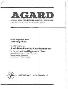
Figure 1. Comparison between the spatial x-interval and time averaged velocity profiles u(z) (triangles), the dynamically rescaled velocity profile u∗ (zv∗ ) (circles – for the notation we refer to section 3), and the Prandtl-Blasius velocity profile (solid line) near the bottom plate obtained experimentally at Ra = 1.8 × 10¹¹ and P r = 5.4 (working fluid water).
the maximum horizontal velocity [u(z)]max , and Re is the Reynolds number based on [u(z)]max . These papers highlight the need to study the nature of the BL profiles, both velocity and temperature, in turbulent thermal RB convection. Considerable progress on this issue has recently been achieved by Zhou & Xia (2009) who have experimentally studied the velocity BL for water (P r = 4.3) with particle image velocimetry (PIV). They found that, since the dynamics above and below the range of the boundary layer is different, a time-average at a fixed height z above the plate with respect to the laboratory (or container) frame will sample a mixed dynamics, one pertaining to the BL range and the other one pertaining to the bulk, because the measurement position will be sometimes inside and sometime outside of the fluctuating width of the boundary layer. To make a clean separation between the two types of dynamics, Zhou & Xia (2009) studied the BL quantities in a time-dependent frame that fluctuates with the instantaneous BL thickness itself. Within this dynamical frame, they found that the mean velocity profile well agrees with the theoretical Prandtl-Blasius laminar BL profile. In figure 1 we show the essence of the results, again for the velocity boundary layer but for somewhat larger P r, now P r = 5.4. (For details of the experiment and the apparatus used, please see Xia, Sun & Zhou 2003; Zhou & Xia 2009). Also here the method of using the time dependent frame works as good as for the P r = 4.3 case of Zhou & Xia (2009). While at the large Ra = 1.8 × 10¹¹ the time and space averaged velocity profile (triangles) already considerably deviates from the Prandtl-Blasius profile (solid line), the dynamically rescaled profile (circles) perfectly agrees with the PrandtlBlasius profile. Thus a dynamical algorithm has been established to directly characterize the BL properties in turbulent RB systems, which is mathematically well-defined and requires no adjustable parameters. The questions which immediately arise are: (i) Does this dynamical rescaling method also work for the temperature field, giving good agreement with the (Prandtl number dependent) Prandtl-Blasius temperature profile? (ii) And does the method also work for lower P r, where the velocity field is more turbulent? Both these questions cannot be answered with the current Hong Kong experiments, as PIV only provides the velocity field and not the temperature field, and as PIV has not yet been established in gaseous RB, i.e., at low P r number Rayleigh-B´enard flows.
4
Q. Zhou et al.
In the present paper we will answer these two questions with the help of direct numerical simulations (DNS). To avoid the complications of oscillations and rotations of the large scale convection roll plane and as the Prandtl-Blasius theory is a 2D theory anyhow we will restrict ourselves to the 2D simulations of Sugiyama et al. (2009). Our results will show that Zhou & Xia (2009)’s idea of using time-dependent coordinates to disentangle the mixed dynamics of BL and bulk works excellently also for the temperature field and also for low P r flow. I.e., if dynamically rescaled, both velocity and temperature BL profiles can be brought into excellent agreement with the theoretical Prandtl-Blasius BL predictions, for both larger and lower P r.
2. DNS of the 2D Oberbeck-Boussinesq equations The numerical method has been explained in detail in Sugiyama et al. (2009). In a nutshell, the Oberbeck-Boussinesq equations with no-slip velocity boundary conditions at all four walls are solved for a 2D RB cell with a fourth-order finite-difference scheme. The aspect ratio is Γ ≡ D/L = 1.0, the Rayleigh number Ra = 108 − 109 , and the Prandtl number either P r = 4.3 (water) or P r = 0.7 (gas). Sugiyama et al. (2009) have provided a detailed code validation. As the governing equations are strictly Oberbeck-Boussinesq, there exists a top-bottom symmetry. We therefore discuss only the velocity and temperature profiles near the bottom plate. For the temperature profiles, we introduce the non-dimensional temperature Θ(z, t), defined as Θ(z, t) =
θbot − θ(z, t) , ∆/2
(2.1)
where θbot is the temperature of the bottom plate. In this definition, Θ(H) = 2 and Θ(0) = 0 are the temperatures for the top and bottom plates, respectively, and Θ(H/2) = 1 is the mean bulk temperature.
3. Dynamical BL rescaling The idea of the Zhou & Xia (2009) method is to construct a dynamical frame that fluctuates with the local instantaneous BL thickness. To do this, first the instantaneous kinematic and thermal BL thicknesses are determined using the algorithm introduced by Zhou & Xia (2009). To reduce data scatter, the horizontal velocity and temperature profiles at each discrete time t, u(z, t) and Θ(z, t), are obtained by averaging the velocity and temperature fields along the x-direction (horizontal) over the range 0.475 < x/D < 0.525. Figures 2(a) and (b) show examples of u(z, t) and Θ(z, t) versus the normalized height z/H, respectively, of the DNS data obtained at Ra = 109 and P r = 0.7. Both u(z, t) and Θ(z, t) rise very quickly from 0 to either the instantaneous maximum velocity or to the bulk temperature within very thin layers above the bottom plate. While after reaching its maximum value, u(z, t) slowly decreases in the bulk region of the closed convection cell, Θ(z, t) reaches and stays nearly constant at the bulk temperature Θ = 1. To see the velocity and the temperature in the vicinity of plates more resolved, we plot the enlarged near-plate parts of the u(z, t) and Θ(z, t) profiles in figures 2 (c) and (d). One sees that both profiles enjoy a linear portion near the plate. The instantaneous velocity BL thickness δv (t) is then defined as the distance from the plate at which the extrapolation of the linear part of the velocity profile meets the horizontal line passing through the instantaneous maximum horizontal velocity, and the instantaneous thermal BL thickness δth (t) is obtained as the distance from the plate at which the extrapolation
5
Prandtl-Blasius temperature and velocity BL profiles in turbulent RBC 0.10 2.0 0.05
1.5
Θ (z,t)
u(z, t) (m/s)
(b)
(a)
0.00
1.0 0.5
−0.05
0.0 −0.10
0.0
0.2
0.4
0.6
0.8
1.0
0.0
0.2
0.4
z/H
0.6
0.8
1.0
z/H
0.10
1.2
0.8
Θ (z,t)
u(z, t) (m/s)
1.0
0.05
δυbot (t ) / H
δ thbot (t ) / H
0.4
(c) 0.00 0.00
0.6
0.02
0.04
(d)
0.2 0.0 0.00
z/H
0.02
0.04
z/H
Figure 2. Examples of (a) an instantaneous horizontal velocity profile u(z, t) and (b) a normalized instantaneous temperature profile Θ(z, t), averaged over 0.475 < x/D < 0.525. The DNS data are obtained at Ra = 109 and P r = 0.7. (c) and (d) show enlarged portions of the velocity and temperature profiles near the bottom plate, respectively. The two tilted dashed lines are linear fits to the linear parts of the velocity and temperature profiles near the plate and the two horizontal dashed lines mark the instantaneous maximum horizontal velocity and the bulk temperature Θ = 1, respectively. The distances of there crossing points from the plate define the bot instantaneous BL thicknesses δv,th (t). The instantaneous profiles are not top-down symmetric, the time averaged ones are. Within our present statistical error our data are consistent with zero thermal gradient in the bulk.
of the linear part of the temperature profile crosses the horizontal line passing through the bulk temperature. The arrows in figures 2(c) and (d) illustrate how to determine δv (t) and δth (t) as the crossing point distances. With these measured δv (t) and δth (t), we can now construct the local dynamical BL ∗ frames at the plate’s center. The time-dependent rescaled distances zv∗ (t) and zth (t) from the plate in terms of δv (t) and δth (t), respectively, are defined as ∗ zv∗ (t) ≡ z/δv (t) and zth (t) ≡ z/δth (t).
(3.1)
∗ The dynamically time averaged mean velocity and temperature profiles u∗ (zv∗ ) and Θ∗ (zth ) in the dynamical BL frames are then obtained by averaging over all values of u(z, t) and Θ(z, t) that were measured at different discrete times t but at the same relative positions ∗ zv∗ and zth , respectively, i.e., ∗ ∗ u∗ (zv∗ ) ≡ hu(z, t)|z = zv∗ δv (t)i and Θ∗ (zth ) ≡ hΘ(z, t)|z = zth δth (t)i.
(3.2)
We first discuss our results from the simulation performed at P r = 4.3, the Prandtl number corresponding to water at 40 ◦ C. Figure 3(a) shows the u∗ (zv∗ ) profile (circles), normalized by its maximum value [u∗ (zv∗ )]max , obtained at Ra = 108 . For comparison,
Q. Zhou et al. 1.0
1.0
(a)
0.8
Θ *(z*th ), Θ (z)
u*(z*υ )/[u*(z*υ )]max , u(z)/[u(z)]max
6
0.6
u*(z*υ )
0.4
u(z) PB profile
0.2 0.0
0
1
,η zυ*z*, , zz//λλthυbot
2
(b)
0.8 1.0
0.6 0.4
0.9
0.2
3
0.0
1.0
0
1
1.5
,η zth*z*, , zz//λλthbot th
2.0
2
2.5
3
Figure 3. Comparison among (a) velocity profiles: dynamical frame based u∗ (zv∗ ) (circles), laboratory frame based u(z) (triangles), and the Prandtl-Blasius velocity profile (solid line), ∗ and (b) the corresponding temperature profiles: Θ∗ (zth ) (circles), Θ(z) (triangles), and the Prandtl-Blasius temperature profile (solid line) near the bottom plate. All results obtained numerically at Ra = 108 and P r = 4.3. The inset of (b) shows enlarged portions of the profiles around the thermal boundary layers’ mergers to the bulk.
we also plot in the figure the time-averaged horizontal velocity profile u(z) (= hu(z, t)i) (triangles), obtained from the same simulation. The solid line represents the PrandtlBlasius velocity BL profile, the initial slope of which is matched to that of the measured profiles (cf. Ahlers et al. 2006). For the range zv∗ . 2 the u∗ (zv∗ ) profile obtained in the dynamical frame agrees well with the Prandtl-Blasius profile, while the time-averaged u(z) profile obtained in the laboratory frame obviously is much lower than the PrandtlBlasius profile in the region around a few kinematic BL widths. - Note that for zv∗ & 2 the u∗ (zv∗ ) profile deviates gradually from the Prandtl-Blasius profile because u∗ (zv∗ ) decreases in the bulk region of the closed convection system down to 0 in the center and then changes sign. The Prandtl-Blasius profile, instead, describes the situation of an asymptotically constant, nonzero flow velocity. - These DNS results are similar to those found experimentally in a rectangular cell (Zhou & Xia 2009). Figure 3(b) shows a direct comparison among the temperature profiles obtained from ∗ the same simulation: the dynamical frame based Θ∗ (zth ) (circles), the laboratory frame time-averaged temperature profile Θ(z) (= hΘ(z, t)i) (triangles), and the Prandtl-Blasius ∗ ) and Θ(z) profiles are consistent with temperature profile. At first glance both the Θ∗ (zth the Prandtl-Blasius thermal profile. However, looking more carefully at the region around ∗ the thermal BL to bulk merger (the inset of figure 3(b)), one notes that the Θ∗ (zth ) profile obtained in the dynamical frame is significantly closer to the Prandtl-Blasius profile than the time-averaged Θ(z) profile obtained in the laboratory frame, indicating that the dynamical frame idea of Zhou & Xia (2009) works also for the thermal BL. Taken together, figures 3(a) and (b) illustrate that both the kinematic and the thermal BLs in turbulent RB convection are of Prandtl-Blasius type, which is a key assumption of the GL theory (Grossmann & Lohse 2000, 2001, 2002, 2004), and the dynamical frame idea of Zhou & Xia (2009) can achieve a clean separation for both temperature and velocity fields between their BL and bulk dynamics. We next turn to the simulation performed at P r = 0.7, a Prandtl number typical for gases, which is relevant in all atmospheric processes and many technical applications. Figures 4(a) and (b) show direct comparison between the temperature and velocity profiles, respectively, at Ra = 109 . Again, around the BL-bulk merger range the laboratory frame time-averaged profiles are found to be obviously lower than the Prandtl-Blasius
1.0
(b)
0.8 0.6
u*(z*υ )
0.4
u(z) PB profile
0.2 0.0
7
1.0
(a)
Θ *(z*th ), Θ (z)
u*(z*υ )/[u*(z*υ )]max , u(z)/[u(z)]max
Prandtl-Blasius temperature and velocity BL profiles in turbulent RBC
0
1
zυz*, , zz//λλ η *
2
0.8 0.6
Θ *(z*th )
0.4
Θ (z) PB profile
0.2
3
0.0
0
bot , vυ
1
zth*z*, , zz//λλthbot ,η th
2
3
Figure 4. Comparison between (a) velocity profiles: dynamical u∗ (zv∗ ) (circles), laboratory u(z) (triangles), and the Prandtl-Blasius laminar velocity profile (solid line), and (b) temperature ∗ profiles: dynamical Θ∗ (zth ) (circles), laboratory Θ(z) (triangles), and the Prandtl-Blasius laminar temperature profile (solid line) near the bottom plate, all obtained numerically at Ra = 109 and P r = 0.7, representative for gases.
profile. This once more indicates that the time-averaged BL quantities obtained in the laboratory frame are contaminated by the mixed dynamics inside and outside the fluctu∗ ating BLs. On the other hand, within the dynamical frame, both u∗ (zv∗ ) and Θ∗ (zth ) are found to agree pretty well with the Prandtl-Blasius laminar BL profiles, indicating that the dynamical frame idea works also for the turbulent RB system with working fluids whose Prandtl numbers are of the same order as those for gases.
4. Shape factors of the velocity and temperature profiles Let us now quantitatively compare the differences between the Prandtl-Blasius profile and the profiles obtained from both simulations and experiments for various Ra and various P r. The shapes of the velocity and temperature (thermal) profiles, labeled by i = v or i = th, can be characterized quantitatively by their shape factors Hi , defined as (Schlichting & Gersten 2004), Hi =
λdi , λm i
i = v, th.
(4.1)
λdi and λm i denote, respectively, the displacement and the momentum thicknesses of the profile, namely, Z ∞ Z ∞ Y (z) Y (z) Y (z) d m λi = {1 − }dz and λi = {1 − }{ }dz. (4.2) [Y (z)] [Y (z)] [Y (z)] max max max 0 0 Here Y (z) = u(z) is the velocity profile if i = v and Y (z) = Θ(z) the thermal profile if i = th. The deviation of these profiles from the Prandtl-Blasius profile is then measured by δHi = Hi − HiP B , (4.3) where HiP B is the shape factor for the respective Prandtl-Blasius laminar BL profile. If a given profile exactly matches the Prandtl-Blasius profile, δHi is zero. Note that the Prandtl-Blasius velocity profile shape factor HvP B = 2.59 is independent of P r, while the PB thermal Prandtl-Blasius BL profile shape factor Hth varies with P r. Figure 5(a) shows the shape factors Hi (P r) of the thermal and the velocity PrandtlBlasius BL profiles as functions of P r and figure 5(b) shows the corresponding thermal
8
Q. Zhou et al. 2.65 1.0
(a) 2.60
HυPB
2.50
Hth 10−1
100
101
Θ *(z*th )
PB
Hυ , Hth
PB
0.8
2.55
2.45 10−2
(b)
0.6
Pr = 0.01 (Hth
0.4
Eq. (4.4) (n = 0) (H = 2) Eq. (4.4) (n = 0.3) (H = 1.91) Linear (H = 3)
0.2 0.0
= 2.45)
= 2.52)
Pr = 1 (HthPB = 2.59)
PB
102
PB
PB
Pr = 0.1 (Hth
0
Pr
1
2
3
z*th
Figure 5. (a) The shape factors for the thermal (solid line) and velocity (dashed line) PB Prandtl-Blasius BL profiles as function of P r. The asymptotic value Hth (P r ≫ 1) is 2.61676... PB and Hv = 2.59. Both Prandtl-Blasius BL profiles for the velocity and for the temperature coincide for P r = 1. (b) The thermal Prandtl-Blasius BL profiles for three (four) P r numbers and the reference linear and exponential profiles, see (4.4); in the figure’s resolution the thermal profile for P r = 100 is indistinguishable from that of P r = 1. Note that the shape factor of the thermal Prandtl-Blasius BL profile decreases with decreasing P r due to the slower approach to its asymptotic level 1. ∗ profiles as functions of zth for three different P r. Note that the Prandtl-Blasius velocity BL profile is identical to the thermal one for P r = 1. The two figures show that the therPB mal shape factor Hth decreases with decreasing P r. We attribute this to the decrease of the temperature profiles in the BL range and the corresponding increase of the tails for lower P r. Thus we expect that the slower approach to the asymptotic height 1 of the thermal profiles in the laboratory frame in figures 3 and 4 should lead to a negative deviation of their Hth ’s from the respective Prandtl-Blasius values, cf. figure 6. In contrast, a positive δHi is obtained if the profile runs to its asymptotic level faster than the Prandtl-Blasius profile. To see this more clearly, we have plotted in figure 5(b) also two extreme cases, the linear and the exponential profiles. Using (4.2) one calculates the ∗ ∗ shape factor 3 for the linear profile Θ∗ (zth ) = min(1, zth ) and the shape factor 2 for the ∗ ∗ ∗ exponential one Θ (zth ) = 1 − exp(−zth ). The H-decreasing effect by lowering the profile can also be demonstrated by analyzing some profiles analytically. Using a combination of exponential profiles, ∗ ∗ ∗ Θ∗ (zth ) = 0.5(1 − exp(−(1 − n)(zth )) + 0.5(1 − exp(−(1 + n)zth )),
(4.4)
with 0 6 n < 1 one can evaluate, using (4.2), that the shape factor for small n is H(n) ≈ H(n = 0) − n2 = 2 − n2 .
(4.5)
As is shown in figure 5(b) the profile for n > 0 is below the profile for n = 0. This analytical example again reflects what we found as the characteristic difference between the laboratory frame profiles as compared to the dynamical frame profiles. Figure 6(a) shows the velocity shape factor deviations δHv (open symbols) and δHv∗ (solid symbols) as obtained from simulations at P r = 0.7 (circles) and P r = 4.3 (triangles) as well as from experiments at P r = 5.4 (squares). Here, δHv is calculated with the time averaged profile u(z) in the laboratory frame, while δHv∗ is calculated with the dynamical, time-dependent frame profile u∗ (zv∗ ). The laboratoty frame based deviations turn out to be definitely smaller than zero. In contrast, the shape factor deviations δHv∗ for the dynamical frame profiles obviously are much closer to zero. A similar result is ∗ found for the thermal BLs: Figure 6(b) shows δHth (open symbols) and δHth (solid
Prandtl-Blasius temperature and velocity BL profiles in turbulent RBC 0.5
(b)
linear profile
0.0
0.0
δH*th , δHth
δH*υ , δHυ
(a)
−0.5 exponential profile −1.0
9
0.2
108
109
1010
Ra
1011
−0.2 −0.4 −0.6 108
109
Ra
Figure 6. The Ra-dependence of the deviations of the profile shape factors from the respective Prandtl-Blasius shape factors. (a) Laboratory frame δHv (open symbols) and dynamical frame ∗ δHv∗ (solid symbols); (b) laboratory frame δHth (open symbols) and dynamical frame δHth (solid symbols); all from simulations performed at P r = 0.7 (circles), P r = 4.3 (triangles), and from experiments at P r = 5.4 (squares).
∗ symbols), versus Ra, for the same P r number simulations. Again δHth is nearly zero, whereas δHth is significantly off. Thus these quantitative deviation measures again indicate that the algorithm using the dynamical coordinates can effectively disentangle the mixed dynamics inside and outside the fluctuating BLs.
5. Conclusions In summary, we have studied the velocity and temperature BL profiles in turbulent RB convection both numerically and experimentally. We extended previous results to different Prandtl numbers and in particular to thermal BLs. The results show that both the velocity and the temperature BLs (at least in the plates’ center region) are of laminar Prandtl-Blasius type in the co-moving dynamical frame in turbulent thermal convection for the parameter ranges studied. However, the fluctuations of the BL widths, induced by the fluctuations of the large-scale mean flow and the emissions of thermal plumes, cause measuring probes at fixed heights above the plate to sample a mixed dynamics, one pertaining to the BL range and the other one pertaining to the bulk. This is the reason why the time-averaged velocity and temperature profiles measured in previous work in fixed laboratory (RB cell) frames deviate from the Prandtl-Blasius profiles. To disentangle that mixed dynamics, we constructed a dynamical BL frame that fluctuates with the instantaneous BL thicknesses. Within this dynamical frame, both velocity and temperature profiles are very well consistent with the classical Prandtl-Blasius laminar BL profiles, both for lower and larger P r (from 0.7 to 5.4). We have thus validated the idea and algorithm of using dynamical coordinates over a range of P r and Ra for both kinematic and thermal BLs and have shown that the Prandtl-Blasius laminar BL profile is a valid description for the BLs of both velocity and temperature in turbulent thermal convection. Laminar Prandtl-Blasius BL theory in turbulent RB thermal convection has thus turned out to indeed be valid not only scaling wise, but also in the time average as seen from the dynamical frame, co-moving with the local, instantaneous BL widths. We gratefully acknowledge support of this work by the Natural Science Foundation of Shanghai (No. 09ZR1411200), “Chen Guang” project (No. 09CG41)(Q.Z.), by the Research Grants Council of Hong Kong SAR (Nos. CUHK403806 and 403807) (K.Q.
10
Q. Zhou et al.
X), and by the research programme of FOM, which is financially supported by NWO (R.J.A.M.S. and D.L.). REFERENCES Ahlers, G., Brown, E., Fontenele Araujo, F., Funfschilling, D., Grossmann, S. & Lohse, D. 2006 Non-Oberbeck-Boussinesq effects in strongly turbulent Rayleigh-B´enard convection. J. Fluid Mech. 569, 409–445. Ahlers, G., Calzavarini, E., Fontenele Araujo, F., Funfschilling, D., Grossmann, S., Lohse, D. & Sugiyama, K. 2008 Non-Oberbeck-Boussinesq effects in turbulent thermal convection in ethane close to the critical point. Phys. Rev. E 77, 046302. Ahlers, G., Fontenele Araujo, F., Funfschilling, D., Grossmann, S. & Lohse, D. 2007 Non-Oberbeck-Boussinesq effects in gaseous Rayleigh-B´enard convection. Phys. Rev. Lett. 98, 054501. Ahlers, G., Grossmann, S. & Lohse, D. 2009 Heat transfer and large scale dynamics in turbulent Rayleigh-B´enard convection. Rev. Mod. Phys. 81, 503–537. Castaing, B., Gunaratne, G., Heslot, F., Kadanoff, L., Libchaber, A., Thomae, S., Wu, X.-Z., Zaleski, S. & Zanetti, G. 1989 Scaling of hard thermal turbulence in Rayleigh-B´enard convection. J. Fluid Mech. 204, 1–30. Dubrulle, B. 2001 Logarithmic corrections to scaling in turbulent thermal convection. Eur. Phys. J. B 21, 295–304. Dubrulle, B. 2002 Scaling in large prandtl number burbulent thermal convection. Eur. Phys. J. B 28, 361–367. Grossmann, S. & Lohse, D. 2000 Scaling in thermal convection: a unifying theory. J. Fluid Mech. 407, 27–56. Grossmann, S. & Lohse, D. 2001 Thermal convection for large prandtl numbers. Phys. Rev. Lett. 86, 3316–3319. Grossmann, S. & Lohse, D. 2002 Prandtl and rayleigh number dependence of the Reynolds number in turbulent thermal convection. Phys. Rev. E 66, 016305. Grossmann, S. & Lohse, D. 2004 Fluctuations in turbulent Rayleigh-B´enard convection: The role of plumes. Phys. Fluids 16, 4462–4472. Lohse, D. & Xia, K.-Q. 2010 Small-scale properties of turbulent Rayleigh-B´enard convection. Annu. Rev. Fluid Mech. 42, 335–364. Malkus, M. V. R. 1954 The heat transport and spectrum of thermal turbulence. Proc. R. Soc. Lond. A 225, 196–212. du Puits, R., Resagk, C. & Thess, A. 2007 Structure of the thermal boundary layer in turbulent Rayleigh-B´enard convection. Phys. Rev. Lett. 99, 234504. Qiu, X.-L. & Xia, K.-Q. 1998 Viscous boundary layers at the sidewall of a convection cell. Phys. Rev. E 58, 486–491. Schlichting, H. & Gersten, K. 2004 Boundary Layer Theory. Springer, 8th ed. Shishkina, O. & Thess, A. 2009 Mean temperature profiles in turbulent Rayleigh-B´enard convection of water. J. Fluid Mech. 633, 449–460. Shraiman, B. I. & Siggia, E. D. 1990 Heat transport in high-rayleigh-number convection. Phys. Rev. A 42, 3650–3653. Siggia, E. D. 1994 High rayleigh number convection. Annu. Rev. Fluid Mech. 26, 137–168. Stevens, Richard J. A. M., Verzicco, R. & Lohse, D. 2010 Radial boundary layer structure and Nusselt number in Rayleigh-B´enard convection. J. Fluid Mech. 643, 493–507. Sugiyama, K., Calzavarini, E., Grossmann, S. & Lohse, D. 2009 Flow organization in nonOberbeck-Boussinesq Rayleigh-B´enard convection in water. J. Fluid Mech. 637, 105–135. Sun, C., Cheung, Y.-H. & Xia, K.-Q. 2008 Experimental studies of the viscous boundary layer properties in turbulent Rayleigh-B´enard convection. J. Fluid Mech. 605, 79–113. Xia, K.-Q., Sun, C. & Zhou, S.-Q. 2003 Paricle image velocimetry measurements of the velocity field in turbulent thermal convection. Phys. Rev. E 68, 066303. Zhou, Q. & Xia, K.-Q. 2009 Measured instantaneous viscous boundary layer in turbulent Rayleigh-B´enard convection. Phys. Rev. Lett. submitted.