Precise Exception Handling for a Self-Timed Processor William F. Richardson Computer Science Department University of Utah Salt Lake City, UT 84112
[email protected]
[email protected]
Abstract Self-timed systems structured as multiple concurrent processes and communicating through self-timed queues are a convenient way to implement decoupled computer architectures. Machines of this type can exploit instruction level parallelism in a natural way, and can be easily modified and extended. However, providing a precise exception model for a self-timed micropipelined processor can be difficult, since the processor state does not change at uniformly discrete intervals. We present a precise exception method implemented for Fred, a self-timed, decoupled, pipelined computer architecture with out-of-order instruction completion.
1. Introduction Fred 1 is an architecture for a self-timed processor structured as a set of communicating micropipelines [9]. The basic Fred architecture is based roughly on the NSR (Non-Synchronous RISC) architecture developed at the University of Utah [1,5]. The NSR is a simple 16-bit machine designed to explore the potential of self-timed organization for computer design, but includes little support for anything but the basic microprocessor features. The Fred architecture [6] borrows many ideas from the NSR. However, Fred includes 32-bit data paths and memory addressing, provides a larger register file, and extends the instruction set in a variety of ways that make the architecture more realistic and more comparable to commercial microprocessors. More importantly, Fred provides a precise exception-handling model that operates in the extremely concurrent environment of a self-timed processor. This exception-handling model must operate in a decoupled environment where instruction completion is not only out of order, but where instructions may complete at any time relative to each other because of the self-timed nature of the processor. Put another way, the state of the processor is not well defined at any particular time, such as on a particular edge of a clock signal. Standard techniques used in synchronous processors for providing precise exceptions cannot be used in a concurrent, self-timed envi1. “Fred” is not an acronym, and it doesn’t mean anything. It’s just a name, like “SPARC” or “Alpha.”
Copyright 1995 IEEE
Erik Brunvand Computer Science Department University of Utah Salt Lake City, UT 84112
ronment. We describe a method of providing precise exceptions in a self-timed, decoupled, pipelined processor architecture with out-of-order instruction completion. The additional circuitry required to add this exception model to the architecture is on the same order as that needed for synchronous processors of similar complexity, but operates in a somewhat different way.
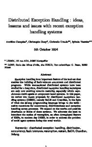
2. The Fred Architecture Fred consists of several independent self-timed processes which communicate via FIFO micropipeline queues. Figure 1 shows the basic organization. Each box is an independent process. All processor data paths (shown as wires in the figure) may be pipelined to an arbitrary depth without affecting the computational results. Because Fred uses self-timed micropipelines in which pipeline stages communicate locally only with neighboring stages to pass data, there is no extra control circuitry involved in adding additional pipeline stages. Multiple independent functional units allow several instructions to be in progress at a given time. Because the machine organization is self-timed, the functional units may take as long or short a time as necessary to complete their function. One of the performance advantages of a self-timed organization is related to this ability to finish an instruction as soon as possible, without waiting for the next discrete clock cycle. It also allows the machine to be upgraded incrementally by replacing functional units with higher performance circuits after the machine is built, with no global consequences or retiming. The performance benefits of the improved circuits are realized by having the acknowledgment produced more quickly, so that the instructions that use that circuit finish faster. Fred uses a Harvard memory architecture, with separate paths for instructions and data. Fred contains 32 32-bit general purpose registers, two of which have special usage. Register r0 is hardwired to zero, and register r1 is used to access the R1 Queue. This data pipeline is used to queue up data for later use by another part of the instruction stream [6,12]. Loads from memory, for example, might be queued in the R1 Queue by using register r1 as the destination. By using r1 as a source register, a later instruction dequeues the next word from the R1 Queue and uses it as an operand. It may be possible to subsume some of the memory latency by queuing up loaded data in
Reproduction without permission is prohibited.
Set/Clear
Instruction Memory
Scoreboard
Clear
Read Operand Request Queue
Arithmetic Unit Logic Unit Control Unit
Results
Results
Results
Results
Read Data
Execute Unit
Write Data
Address
Memory Unit
R1 Queue
Done Queue
Distributor
Branch Unit
Register File
Operand Queue
Instructions
Exception Branch Queue
Branch Queue
Prefetch Address
Dispatch Unit
Data Memory Figure 1. Fred Block Diagram. Black lines are primary data paths; gray lines are control paths. All data and control paths are pipelined queues. the R1 Queue in advance of its use. Actually, data from any of the functional units may be queued into the R1 Queue to implement a form of software-controlled register renaming. Instructions are prefetched and issued by the Dispatch Unit, which uses a 31-bit register scoreboard to avoid data hazards. The instructions are issued in program order, but may complete in any order. However, instructions which write into the R1 Queue are forced to complete sequentially. There are five independent functional units in the prototype implementation of Fred: Logic, Arithmetic, Memory, Branch, Control. These functional units plus the Distributor make up the Execute Unit. The Distributor takes incoming instructions and operands, matches them up where needed, and routes the combined data to appropriate functional units for execution. Instructions pass through the Distributor in program order but may complete in any order as each pipeline depth may vary, and each functional unit may take more or less time to execute a given instruction. The outgoing side of the Register File sends operands to the Execute Unit in response to requests from the Dispatch Unit. The incoming side accepts results from each functional unit independently, via a separate pipeline from each unit. There is no contention in writing to registers, since the register scoreboard is used by the Dispatch Unit to ensure that instructions are not dispatched until all data hazards are resolved. Each functional unit can also write its results to the R1 Queue.
Copyright 1995 IEEE
Program branching takes place in two parts. Branch targets (and the condition code bit used to determine whether to take the branch) are computed and placed in the Branch Queue by one instruction, but are removed and used to modify the Program Counter by a subsequent “doit” instruction (to avoid extra instruction fetches, the doit can be implicitly inserted into the instruction stream by setting a bit available in the opcode of any other instruction). This separation allows for a variable number of “delay slots,” and lets us play some other nifty tricks. For example, we always get correct prefetching information, since the direction of the branch is known as soon as the target is placed in the queue by the Branch Unit. Deadlocking the processor is theoretically possible. Because both the R1 Queue and the Branch Queue are filled and emptied via two separate instructions, it is possible to issue an incorrect number of these instructions so that the producer/consumer relationship of the queues is violated. Fred’s dispatch logic will detect these cases, and take an exception before an instruction sequence is issued that would result in deadlock.
3. Exception Requirements There are three general causes for exceptions: software traps (including illegal opcodes), external interrupts, and process exceptions (such as memory faults). When exceptions occur, it is necessary for the processor to temporarily stop executing its current instruction stream and handle whatever conditions caused the exception. Often,
Reproduction without permission is prohibited.
once the exception has been dealt with, the processor must be able to resume as though no exception had occurred. Precise exception models allow the programmer to view the processor state as though the exception occurred at a point exactly between two instructions, such that all instructions before that point have completed while all those after have not yet started. In a heavily pipelined architecture, where instructions execute concurrently and possibly out of order, identifying a precise point for exception handling can be costly. Several methods have been developed to deal with this problem [3,7,8]. However, clocked systems have the advantage that the state of the processor is available to the processor’s control logic at every clock cycle. In a selftimed processor like Fred, this is not the case. One characteristic of a self-timed system is that while the completion of a task is reported through a handshake of some sort, the actual completion time for that event is not particularly well-defined with respect to any global signal such as a clock. While this may provide advantages in achieving average-case performance or simplifying modular composition [2], it makes exception processing difficult. Much of the state of the Fred processor is contained in the pipelines but it is problematic to determine exactly how many items are in a particular pipeline at a given moment in time. This problem has been addressed in part by the AMULET group at the University of Manchester [4], who have built a self-timed implementation of the ARM. However, its precise exception model is a simple one since its single ALU causes all instructions to issue and complete sequentially. Fred’s decoupled concurrent architecture requires a more general solution.
cause exceptions (such as xor r2,r3,r4) do not have to report their status, and can be removed from the IW when they are dispatched.
3.1 The Instruction Window
3.3 Out-of-Order Completion
To resolve the uncertainty regarding instruction status, Fred uses an Instruction Window (IW), similar to that described in [10], to fetch and dispatch instructions. The IW is a set of internal registers located in the Dispatch Unit, which tracks the state of all current instructions. Each slot in the IW contains information about each instruction, such as its opcode, its address, its current status, and various other parameters. As each instruction is fetched, it is placed into the IW. New instructions may continue to be added to the IW independently, as long as there is room for them. Instructions are issued from the IW in program order when all their data dependencies are satisfied. Each issued instruction is assigned a tag which uniquely distinguishes it from all other current instructions. When an instruction completes, it uses this tag to report its status to back to the Dispatch Unit. The status is usually an indication that the instruction completed successfully, but when an instruction is unsuccessful it returns an exception status to the Dispatch Unit, which then begins exception processing. Instructions are removed from the IW only after they have completed successfully. Instructions which can never
Because instructions may complete out of order, recoverable exceptions can cause unforeseen WAW hazards. The IW contains enough information to resolve these issues. In [10], provision was made to reduce interrupt latency by aborting issued instructions which would take a long time to complete. In a self-timed processor there is no way to tell how soon an instruction will complete, since there are no clock cycles by which to measure progress. Instead, when an exception occurs we simply allow all outstanding instructions to either complete or fault before handling the exception. It is necessary for a faulting instruction to save its original operands as part of the IW status. For example, consider this code fragment:
Copyright 1995 IEEE
3.2 Data Hazards Data hazards are handled by the Dispatch Unit. RAW and WAR hazards are resolved by using a simple register scoreboard. When an instruction is dispatched, the Dispatch Unit marks the destination register as in use. When the result of the instruction arrives at the register, the Register File clears the scoreboard flag for that register. The Dispatch Unit will not request operands from the Register File unless the source register holds valid data. WAW hazards are handled in the same way. An instruction will not be dispatched unless its destination register is available for writing. Instructions which write to the same destination register complete sequentially, since the second instruction will not be dispatched until the results of the first instruction arrive at the destination register and its scoreboard bit is cleared. For instructions which write to the R1 Queue, the scoreboard bit for register r1 is cleared by the Dispatch Unit when the result has been placed into the R1 Queue, as indicated by the instruction’s completion status. Instructions signal completion as soon as the functional unit which processes them has generated a valid result, even though that result may not yet have reached its final destination. This allows faster sequential access to the R1 Queue, allows exceptions to be recognized earlier, and enables successful instructions to be removed from the IW sooner so that more instructions may be fetched. This early completion signaling has no effect on data hazards.
ld add
r2,r3,r4 r4,r5,r6
The instructions are issued in order. The load instruction uses sources r3 and r4 to compute the effective address. The add instruction then modifies register r4. This is fine, unless the load faults after the add has com-
Reproduction without permission is prohibited.
pleted. The load cannot simply be reissued, since the original value of r4 has been overwritten. By saving the operands as part of the load instruction’s status, software can emulate the operation of the load instruction once the fault has been resolved. It might be possible to abort some instructions involving iterative processing (such as multiply or divide) when exceptions occur. Unfortunately, matters are worse when instructions can be aborted, because all aborted instructions need some way to recover their original operands. This could be done via a history buffer or future buffer, or by storing the original operands as part of the IW slot. By not aborting issued instructions, only those instructions which fault need to report their operands back to the IW as part of their status. This reduces the complexity required of the Dispatch Unit and the Register File, at the expense of widening the data path needed to report instruction status. Some alternatives will be discussed in Section 5.
3.4 Memory Unit In most cases, waiting for outstanding instructions to complete before handling exceptions does not increase the latency by a significant amount, and in fact may reduce the latency when compared with the time needed to save aborted instructions as part of the processor state. The instructions which could make a big difference are those involving the Memory Unit. We haven’t discussed the external memory system here, but it can be assumed to include a multilevel cache system with both fast and slow memory. The interface to the external memory uses a standard self-timed Request/Acknowledge handshake when dispatching loads or stores. Bundled with the acknowledgment is a memory status signal used to indicate exception conditions such as write-protection violations, page faults, cache misses, and so forth. This status signal can allow the processor to take an exception in the event of page faults or even cache misses. When a memory access instruction faults, it returns the fault type and operands to the Dispatch Unit as part of its completion status. All issued instructions are allowed to complete or fault, and those which finish successfully are removed from the IW before exception processing begins. The exception-handling software can then repair the cause of the exception and emulate the memory operation, based on the operands saved in the IW. Program execution can then resume.
3.5 Exception Software When exception processing begins, the processor state includes the IW contents, the address from which the next instruction will be fetched, the Register File, and the contents of the R1 Queue and Branch Queue. Once all outstanding instructions have completed or faulted, the IW is copied to a set of Shadow IW registers visible to the programmer, then cleared. Since all successful instructions are removed from the IW when they complete, the
Copyright 1995 IEEE
Tag
Status
Instruction
1 2 3 4 5 6 7
Issued None None None None None None
add r2,r2,r2 add r1,r2,r2 xor r2,r3,r3 mul r3,r4,r4 and r4,r5,r5 ld r5,r6,r6 add r6,r7,r7
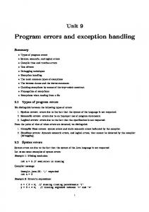
Figure 2. IW with data dependency. Shadow IW contains only faulty and non-issued instructions. This Shadow IW provides a “functionally precise” exception point. The exception model seen by the programmer is not that of a single point where the exception occurred. Instead, there is a “window” (hence the name) of instructions which were in progress. The hardware guarantees that this window will consist only of instructions which either faulted or had not yet issued when the exception occurred. The instructions in the Shadow IW comprise a subset of a portion of the sequential instructions of the program. The missing elements are instructions which completed successfully out of order, and which should not be reissued. To allow additional exceptions or to perform a context switch, the exception software must save the state of the processor. All of the state can be obtained via control registers, except for the contents of the R1 Queue and the Branch Queue, which are not automatically flushed. However, there are control registers which keep a count of the number of items in these two queues. Instructions exist which can be used to manually flush and reload these queues. The other queues do not need special attention. Although the R1 Queue can wait for software to save and restore its contents, the Branch Queue is needed to branch to the exception-handling code. Rather than try to flush this queue in hardware, an additional queue, the Exception Branch Queue, is used for flow control until Branch Queue contents have been saved. The usage of this queue is controlled by a mode bit in a control register, set by the hardware when exception processing begins. Additional exceptions cannot be taken while the Exception Branch Queue is in use, because there is no way to save or recover the processor state. Once the exception condition has been handled, the original state of the processor must be restored. Faulty instructions must be emulated in software and removed from the Shadow IW. Non-issued instructions are left in the Shadow IW. The Branch Queue and R1 Queue are reloaded (if necessary). The rte instruction will restore the IW from the Shadow IW, reenable exceptions, and resume fetching instructions and issuing them from the IW.
4. Exception Example Figure 2 shows a section of a program as it may
Reproduction without permission is prohibited.
Tag
Status
Instruction
2 3 4 5 6 7 8 9
Issued Complete Issued Issued Issued None None None
add r1,r2,r2 xor r2,r3,r3 mul r3,r4,r4 and r4,r5,r5 ld r5,r6,r6 add r6,r7,r7 xor r7,r8,r8 add r8,r9,r9
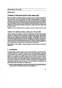
Figure 3. Data dependency resolved. Tag
Status
Instruction
4 5 6 7 8 9 10
Issued Complete Page Fault Issued Complete Issued None
mul r3,r4,r4 and r4,r5,r5 ld r5,r6,r6 add r6,r7,r7 xor r7,r8,r8 add r8,r9,r9 mul r9,r10,r10
Figure 4. IW with exception condition. Tag
Status
Instruction
4 6 10
Overflow Page Fault None
mul r3,r4,r4 ld r5,r6,r6 mul r9,r10,r10
Figure 5. Ready for exception handling. appear in the IW. At this point, the second instruction can’t issue until the top instruction completes (because of the dependency on r2) and the rest must issue sequentially. Figure 3 shows the state soon after that dependency is satisfied. The top instruction has completed and been removed, several additional instructions have been issued (one has completed), and two new instructions have been fetched and placed into the IW. If the load instruction faults, exception processing will take place. Figure 4 shows the state of the IW when the fault is reported. Several instructions have already completed and been removed, while others are still pending. In particular note that the add instruction with tag 7 will modify register r6, which was used by the faulty load instruction. Figure 5 shows the state of the IW once all outstanding instructions have either completed or faulted. Notice that there is more than one faulty instruction now in the IW, and the IW only contains faulty and non-issued instructions, since all completed instructions have been removed. The first faulty instruction in the IW is not the instruction that first signaled an exception. In addition, the add instruction which modified r6 has completed successfully, so the current value of r6 cannot be used to reissue the load instruction. Not shown are the operands for the faulty instructions, which are included in the reported status.
5. Circuit Complexity
Copyright 1995 IEEE
Field valid tag address opcode wat single issued status arg1 arg2
Bits 1 4 30 32 1 1 1 8 32 32
Meaning slot is filled dispatch tag instruction address instruction opcode can be issued only at top of IW inhibits instruction prefetching has been issued completion status for fault recovery for fault recovery
Figure 6. IW slot size. The design of Fred is relatively straightforward. Most of the complexity is in the Dispatch Unit. Data hazards are resolved with a simple 31-bit scoreboard. Normal structural hazards do not require any additional scoreboarding or control, since the flexibility of the micropipelines eliminates the need for inserting artificial pipeline stalls. To prevent deadlock, the Dispatch Unit must be aware of the number of items in the R1 Queue and Branch Queue, but this can be done with a simple shift register. The size of the Instruction Window may have the largest impact on the circuitry needed for the exception handling, since each IW slot requires a significant number of bits. Figure 6 shows the bits needed for each of the IW slots in the current VHDL implementation of Fred (some of the entries relate to issues not covered in this paper). The number of slots in the IW is arbitrary, but obviously will have some effect on performance. A variety of options exist which could reduce the complexity or size of the processor circuitry. Some are discussed below.
5.1 Fewer Control Registers The amount of circuitry needed could be reduced significantly by eliminating the Shadow Instruction Window. Saving the entire IW in a set of control registers at exception time roughly doubles the number of transistors needed to implement the IW. Eliminating the Shadow IW would be an important goal for a physical implementation. This can be done by revising the dispatch logic such that the IW is entirely disabled while the processor state is being saved. The control registers used to access the Shadow IW would actually access the IW itself. This means that instructions are not tracked in any way, and therefore must not cause exceptions. This is not an unreasonable requirement for an exception-handling routine. A second side effect is that the R1 Queue must not be accessed while the IW is disabled. To prevent deadlock and WAW hazards, the Dispatch Unit uses the IW to keep track of the number of items in the R1 Queue, and to scoreboard register r1. If the IW is disabled, this cannot be done correctly. Therefore, a typical exception handler would consist of four parts: 1) save the IW state while the IW is disabled, 2) reenable the IW and save the R1 Queue and Branch Queue contents, 3) reenable the Branch Queue to possibly allow nested exceptions, and 4) continue with
Reproduction without permission is prohibited.
normal exception processing.
5.2 Smaller IW Slots Another contributor to the size of the IW is the number of bits needed for each slot, with the operands of faulty instructions making up nearly half of the total. One alternative is to add some form of history buffer to maintain the original register values. However, doing so would complicate the completion logic without necessarily reducing the size of the processor. Additionally, correctly reversing operations on the R1 Queue is extremely difficult. Another alternative is to change the way in which data dependencies are detected. Because instructions are issued in-order, a simple scoreboard model is all that is needed to resolve register dependencies. Exceptions can violate these in-order dependencies by effectively issuing out of order. If the dispatch logic were revised such that instructions could issue while always avoiding WAW hazards, then the register file contents would be sufficient to reissue faulty instructions. This would also allow instructions to be aborted if desired. By eliminating WAW hazards, the instruction operands would no longer be needed in the IW, reducing its size by nearly fifty percent. However, the complexity of the dispatch logic would increase, since detecting data dependencies in both directions is difficult, and the way in which operands are obtained from the Register File would also require alteration. A more significant drawback would be the possible reduction in program efficiency. The degree of parallelism in most programs is not great [11], yet is enough that some pipelining is possible. With WAW-safe dispatch, no two concurrent instructions can use the same registers for either source or destination. It is questionable whether typical programs have enough parallelism to maintain performance under these conditions.
References [1] Erik Brunvand. The NSR processor. In Proceedings of the 26th Annual Hawaii International Conference on System Sciences, pages 428–435, Maui, Hawaii, January 1993. [2] Alan L. Davis. Asynchronous advantages often cited and NOT often cited. Distributed at the Async94 conference, November 1994. Salt Lake City, Utah. [3] Harry Dwyer and H. C. Torng. An out-of-order superscalar processor with speculative execution and fast, precise interrupts. In Proceedings of the 25th Annual International Symposium on Microarchitecture, pages 272–281, December 1992. [4] S. B. Furber, P. Day, J. D. Garside, N. C. Paver, and J. V. Woods. A micropipelined ARM. In Proceedings of the VII Banff Workshop: Asynchronous Hardware Design, Banff, Canada, August 1993. [5] William F. Richardson and Erik Brunvand. The NSR processor prototype. Technical Report UUCS–92–029, University of Utah, August 1992. ftp://ftp.cs.utah.edu/ techreports/1992/UUCS-92-029.ps.Z. [6] William F. Richardson and Erik Brunvand. Fred: An architecture for a self-timed decoupled computer. Technical Report UUCS–95–008, University of Utah, May 1995. ftp://ftp.cs.utah.edu/techreports/1995/UUCS95-008.ps.Z.
6. Conclusions Precise exception methods commonly used in clocked processors are of doubtful utility for self-timed processors. Identifying a point when the total state of the machine is known is not possible for a machine structured as a collection of concurrently operating self-timed processes. We have described a method of providing functionally precise exceptions for a self-timed, decoupled, pipelined computer architecture with out-of-order instruction completion. This method involves the use of an Instruction Window to keep track of the state of each issued instruction. When the instructions complete or fault, the IW is updated to reflect their new status. When faults occur, further instructions are not issued, pending instructions are allowed to complete (or fault), and exception processing begins. The state of the processor is recovered from the various queues, and can be reloaded upon return from the exception. The complexity of the overall Fred architecture is such that the exception requirements are nontrivial. How-
Copyright 1995 IEEE
ever, the special circuitry required for exceptions is on the same order as that needed for clocked processors of similar complexity. The required control logic is arguably less complex than for globally synchronous processors, and is well-suited to the asynchronous protocols used in selftimed processors. The Fred processor has been implemented in VHDL using the precise exception model just described. All exception cases function correctly, including memory faults, interrupts, deadlock detection, and nested exceptions. The performance effects of internal pipeline lengths and execution times on the various functions, including exception handling, are currently being investigated.
[7] James E. Smith and Andrew R. Pleszkun. Implementing precise interrupts in pipelined processors. IEEE Transactions on Computers, 37(5):562–573, May 1988. [8] Gurindar S. Sohi. Instruction issue logic for high-performance, interruptible, multiple functional unit, pipelined computers. IEEE Transactions on Computers, 39(3):349– 359, March 1990. [9] Ivan Sutherland. Micropipelines. Communications of the ACM, 32(6):720–738, 1989. [10] H. C. Torng and Martin Day. Interrupt handling for out-oforder execution processors. IEEE Transactions on Computers, 42(1):122–127, January 1993. [11] David W. Wall. Limits of instruction-level parallelism. WRL Technical Note TN-15, Digital Western Research Laboratory, 100 Hamilton Avenue, Palo Alto, CA 94301, December 1990. ftp://gatekeeper.dec.com/pub/ DEC/WRL/research-reports/WRL-TN-15.ps. [12] Wm. A. Wulf. The WM computer architecture. Computer Architecture News, 16(1), March 1988.
Reproduction without permission is prohibited.