ISPCS 2009 International IEEE Symposium on Precision Clock Synchronization for Measurement, Control and Communication Brescia, Italy, October 12-16, 2009
Precise Time Synchronization on a High Available Redundant Ring Protocol Jean-Charles Tournier
Karl Weber, Clemens Hoga
ABB Corporate Research Ltd. Baden, Switzerland Email:
[email protected]
Siemens AG, Industry and Energy Sector Nuremberg, Germany Email: {karl.weber;clemens.hoga}@siemens.com
I. I NTRODUCTION An electric substation [1] is a node in the power grid network. It serves the purpose of transmitting and distributing electric energy from power sources to consumers, such as households or industrial plants. An electric substation is made of primary equipment (switchgears, breakers, transformers) and secondary equipment (sensors, merging units, intelligent electronic devices). The secondary equipment aims at protecting and controlling the primary one by sensing and analyzing various data. Since 2004, the IEC61850 standard [2] defines the different communication protocols taking place inside a substation automation in order to promote interoperability among the different manufacturers of secondary equipements (cf. figure 1). One important decision made in the early stage of the standard definition is to base all communications on Ethernet [3] to directly take advantage of the continuous development of the procotol from a software and hardware point of view (e.g. definition of new protocols such as IEEE1588, new switches or IP cores, etc.). Such communications are critical to correctly
Fig. 1. Identification of the different communication protocols defined by IEC61850 inside a substation automation.
operate a substation and need to meet the requirements of high reliability and precise synchronization. IEC61850 defines different classes of synchronization depending on the considered functions. As an example, an event recorder needs to be synchronized by 1 ms to the rest of the
978-1-4244-4392-5/09/$25.00 ©2009 IEEE
system, while the devices involved in the busbar protection function need to be synchronized by less than 4 µs. In addition, reliable communication is a pre-requisite to efficiently perform protection functions. While classical reliable protocols, such as TCP/IP, are not always an option because of the high communication frequency (data are sent at a frequency up to 4KHz, i.e. a period of 250µsec), reliability is usually achieved by mean of physical and/or logical redundancy. Two new protocols have been lately defined to handle separately precise time synchronization and reliability requirements. On one hand, the IEEE1588 protocol [4] defines a precise time synchronization protocol based on a master-slave architecture. The precision achieved by IEEE1588 depends on the exact knowledge of the different paths between a master and slave in order to evaluate the transmission delay between the two entities. On the other hand, HSR [5] (High availability Seamless Ring protocol) defines a ring protocol with no traffic interruption in case of the failure of a link by sending data on each direction on the ring. The duplicate pakcets are transparent to the sender and the receiver and are handled by the HSR switches. While HSR and IEEE1588 seem to be promising candidates for substation automation communications, their simultaneous usage raises interesting challenges as they are based on opposite assumptions. One requires a precise knowledge of the communication paths (IEEE1588), while the other (HSR) transparently sends and receives packets in any direction. In this paper, we are evaluating the different alternatives of implementing IEEE1588 on top of HSR. More precisely, we are looking at the consequences in terms of complexity, network load and time precision of using boundary clocks versus transparent clocks, end to end versus peer to peer transparent cloks, one step versus two step clocks, unicast versus mutlicast communications, and alternate master versus election. The goal is this study is not to give a reference implementation but rather to evaluate the different alternatives of IEEE1588 to understand and evaluate their tradeoff when being implemented on HSR. The reminder of this paper is organized as follows. Section II gives an overview of the high availability seamless ring protocol. Section III presents the different alternatives and
consequences of implementing IEEE1588 on top of HSR. Finally, before concluding the paper, section IV presents the works related to this paper.
bits distinguish a HSR management frame or a HSR payload. Because of the insertion of the HSR tag, the length of the
II. H IGH AVAILABILITY S EAMLESS R ING P ROTOCOL A. Overview The high availability seamless ring protocol or HSR is defined in the standard IEC62439 [5]. HSR aims at providing seamless redundancy in case of a network link failure over a ring topology network. In other words and unlike classical ring protocols such as RSTP [6], HSR guarantees that no packet is lost when a failure occurs. The main principle of HSR resides in the fact that each node is simulteanously connected to each side of the ring and sends the same packet on both directions, i.e. clockwise and counter clockwise (cf. figure 2). Each node are made of integrated switches implementing the HSR logic and are usually programmed on FPGAs. Nodes
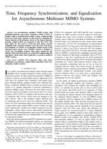
Fig. 3.
Structure of an HSR frame.
frame may exceed the maximum length of 1518 bytes (or 1522 bytes with VLAN tag) allowed by the IEEE 802.3 standard by 6 bytes. But because the traffic in the ring is private, the modification can be done in the switch element to adapt the exceeded frame length and this has no influence on the Ethernet traffic outside the ring. C. Communication rules
Fig. 2. Overview and principles of the high availability seamless ring protocol.
within the ring are restricted to be HSR-capable switching end nodes. General purpose nodes cannot be attached directly to the ring, but require a Redundancy Box (RedBox). A pair of such RedBox can be used to connect hierarchically a HSR to another network. But the frame format must be transformed when the frames enters HSR. It is worth noting that a node has the same MAC address on both ports, and only one IP address is assigned to that address. Redundancy is therefore transparent to the upper layers (e.g. TCP, UDP and IP) and is considered as a layer 2 redundancy. HSR allows the Address Resolution Protocol (ARP) to work the same way as with a classical redundancy protocol. B. Frame format HSR frames are identified uniquely by their source MAC address, destination MAC address and HSR Tag. The frame format is shown in figure 3. The HSR tag is placed at the beginning of the frame to allow early identification of frames for cut-through operation. After the destination address, the source address and the sequence number is received, the frame is uniquely identified. The HSR tag is announced by the dedicated Ethertype = 0x88FB, which is the same as IEC 62439-3s Ethertype. The 4 most significant bits of the next 16
Nodes in HSR work in cut-through mode to decrease the forwarding delay. After the destination address, source address and sequence number have been received and the frame is checked as not received or not sent before, the node begins forwarding the frame over the other port. The cut-through operation is not applied to the receiving port to the host application of the node. The frame passed to the host is always completely received first. Moreover, only good frames are passed to the host. Even though the principles of the protocol remain simple, the decision of receiving, forwarding or discarding a frame by a node is critical. When a frame is received a node shall remove the HSR tagging and pass the modified frame to its higher protocol layer, if this is the first frame of a pair and if the node is the receiver, otherwise discard the duplicate if this is the second frame of a pair. On the other, a node discards a frame if it identifies the frame as a frame that has already been sent in the same direction, which is usually the case for multicast frames but also for unicast frames without a receiver. Likewise, when a node detects that the frame is damaged or truncated while forwarding, it shall append the error sequence foreseen in 802.3 and stop the forwarding operation. These rules remove circulating HSR frames and open the ring, in the same way as an RSTP or similar protocol. Finally, the arrival time difference between two frames of a pair depends on the relative position of the receiving node and of the sending node. Assuming a worst case in which each node in the ring is transmitting at the same time its own frame with the largest size of 1522 octets, each node could introduce 120 µs of delay at 100 Mbit/s. With 50 nodes, in case of a unicast traffic the time skew may exceed 6 ms. III. I MPLEMENTING IEEE1588 ON HSR IEEE1588 and HSR are based on two opposite assumptions. On one hand, IEEE1588 requires an exact knowledge of the path used by each packet. On the other hand HSR hides
Alternative 1 Alternative 2 One step clock Two step clock End-to-end TC Peer-to-peer TC BMC algorithm Alternate master Source MAC address modification Non modification UDP/IP Raw Ethernet mapping Unicast Multicast Cut-through Store and forward mechanism Hard resynchronization Slewing TABLE I L IST OF IEEE1588 ALTERNATIVES CONSIDERED WHILE BEING IMPLEMENTED FOR HSR
the two types of clock is the way they are evaluating the transmission delay between a master and a slave. In the case of an end to end transparent clock on HSR, the difficulty is to enforce that the Sync message and the Delay Req/Resp are going through the same path. Indeed, as shown in figure 4, if one of these messages is taking a different path, the |delaypath1 −delaypath2 | offset calculation is off by . Depending 2 on which node is considered and the size of the ring, the error introduced in the offset calculation can be as big as a couple of millisecond (cf. example given at the end of section 2). Enforcing a common path for each message is against the
the communication paths to the host application by using indifferently a packet coming from either port. This section gives an analyzes of the different options when implementing IEEE1588 on top of HSR by evaluating the conseqences in terms of precision of the synchronization, network load and required modifications of HSR. The intent of this section is not to give the way to implement IEEE1588 on HSR, but rather understand the consequences of each alternatives. The set of alternatives considered during this study is summarized in table I, but only three of them are detailed in this version of the paper due length restriction. A. One step clock vs. two step clock In the context of IEEE1588, a two step clock refers to the use of Follow Up messages and Pdelay Resp Follow Up. Compared to a one step clock, the traffic load of a two step clock is doubled for each Sync and Pdelay Resp Follow Up messages. A two step clock is usually implemented when only partial or no hardware support is available, i.e. a time stamping unit and on the fly frame modification, in order to give a better precision of when a message is sent. On HSR, the tradeoff of using a two step clock is magnified. Indeed, a two step clocks on HSR generates four times more messages than a one step clock on a regular network since each packet is sent on both directions. It shall be noted that the Sync, Delay Req and the respective Follow Up messages are correlated. That means that they have to be consumed from the same port (either clockwise or counter clockwise) otherwise the offset calculation is misleading. A two step clock therefore requires a specific handling of SYNC, Follow Up and Pdelay Resp Follow Up messages from an HSR point of view in order to notify the software stack the port identification on which the message has been received. Duplicate elimination is not allowed in this case and as a matter of fact, the integration of a two step clock would require a dedicated handling of the PTP messages in the HSR context. B. End to end vs. peer to peer transparent clock In a HSR network, each node is obviously a transpatent clock. Even though, implementing each node as a boundary clock is technically feasible, the cascading effect would be desastrous from a synchronization point of view [7]. IEEE1588 proposes two different transparent clocks called end to end and peer to peer. The main difference between
Fig. 4. Illustration of the correct path for an end to end transparent clock on a HSR network.
principle of HSR: a specific handling of IEEE1588 messages is required on HSR. Moreover, if we consider that the SYNC messages are still sent on both directions, each slave needs to evaluate two different transmission delays. From a master point of view, the overall number of Delay Request messages is doubled. In the case of a peer to peer clock, each SYNC message arriving at a slave can be directly interpretated independently of the incoming direction. Indeed, each node between a slave and the master indicates directly in the SYNC message its residence time and the transmission delay with its neighboring node (cf. figure 5). From an IEEE1588 software stack point of view, the use of HSR is therefore transparent but the frequence of received SYNC messages is doubled. Although, the node does not need to differentiate the SYNC messages circulating clockwise or counter clockwise, the peer to peer messages can not be handled as normal HSR messages. Since the purpose of the peer to peer messages are to evaluate the delay transmission of a specific link between two nodes, they can only be exchanged on this specific link. From an HSR point of view, PDelay Request and PDelay Response are specific messages which
more general and address the issue of reliable synchronization protocols. The closest work done in this area is described in [8]. This paper does not look at the different alternatives of implementing IEEE1588 over a highly cascaded network, but rather describe the implementation of a specific one (peer to peer transparent clock) and evaluate the synchronization performance that can be achieved. An related area to the work presented in this paper relates to reliable time synchronization protocol since HSR provides an highly available communication between the master and each slave. Works such as [9], [10] or [11] focus on different ways of achieving reliability. In the context of wireless communications betwen moving sensors, [9] proposes a new synchronization protocol while [11] and [10] are more generic and identifies generic principles for reliable synchronization. V. C ONCLUSION AND FUTURE WORK Fig. 5. Illustration of the SYNC message on HSR using a peer to peer clock.
do not follow the HSR rule. These specific messages can be directly handled at the HSR switch level (i.e. FPGA) in order to be transparent to the software stack and to the HSR logic (i.e. there is no need to identify in the upper layer which packet is sent or received from which port). C. Unicast vs. multicast The IEEE1588 standard defines two ways of addressing SYNC messages: either unicast or multicast. For a multicast addressing, the master node, through HSR, generates, at each synchronization period, two SYNC messages on the ring circulating in opposite direction. On the other hand, a unicast addressing implies a traffic load increase since each node receives a specific SYNC message. As an example, if we consider a ring of 50 nodes, the number of SYNC messages goes up to 49 × 2 = 98 every synchronization period. Another consequence of the unicast addressing reside in the complexity of implementing the HSR logic for a residence time calculation of a transparent clock. In a multicast addressing, each node excepts to calculate the residence time of a SYNC message in one direction once every synchronization round. In this case a single variable is enough to store and perform the calculation of the residence time. In a unicast addressing, several SYNC messages arrives in series and therefore a FIFO-like structure with a maximal size equals to the number of nodes in the ring has to be implemented in order to store the different incoming time. The consequence is therefore an increase complexity of the code managing the transparent clock but more importantly an increase memory requirement which is a scare and expensive resource on a FPGA. IV. R ELATED WORKS Even though HSR and IEEE1588 are new protocols and standards a couple of works are related to the problem tackled in this paper. These works are classified in two area: the first one deals with IEEE1588, while the second one is
This paper presented the different tradeoff in implementing IEEE1588 on top of HSR by evaluating the differents alternatives offered by the time synchronization protocol. The evaluation is based on the accuracy of the achieved synchronization, its complexity and its conformance to the HSR protocol. The next steps of this work is (a) to define a way to implement IEEE1588 on HSR and (b) to validate it by implementing the logic on a FPGA to verify the local logic (i.e. is enough information accessible locally?) as well as the overall system logic (i.e. is the whole ring synchronized?). R EFERENCES [1] Klaus-Peter Brand et al., Substation Automation Handbook. Utility Automation Consulting Lohmann, 2003. [2] IEC, “IEC 61850 - Communication networks and systems in substations,” 2003. [3] IEEEE, “IEEE 802.3-2005 - LAN/MAN CSMA/CD Access Method,” 1997. [4] IEEE Instrumentation and Measurement Society, “IEEE 1588-2008 Standard for a Precision Clock Synchronization Protocol for Networked Measurement and Control Systems,” 2002. [5] IEC, “IEC CDV 62439-3 - Industrial Networks Highly Available Automation Networks, Parallel Redundancy Protocol and High availability Seamless Ring,” 2008. [6] IEEEE, “IEEE 802.1D-2004 - Standard for Local and metropolitan area networks, Media Access Control (MAC) Bridges ,” 2004. [7] Thomas Mueller and Karl Weber, “Impact of Switch Cascading on Time Accuracy,” Wokrshop pn IEEE1588, Standard for a Precision Clock Synchronization Protocol for Networked Measurement and Control Systems, 2003. [8] Sven Meier, Hans Weibel, and Karl Weber2, “IEEE 1588 Syntonization and Synchronization Functions Completely Realized in Hardware,” International IEEE Symposium on Precision Clock Synchronization for Measurement, Control and Communication, 2008. [9] Hwang Soyoung and Baek Yunju, “Reliable time synchronization protocol in sensor networks considering topology changes,” 7th international workshop Distributed computing, Kharagpur, India, 2005. [10] David Mills, “Internet time synchronization: the network time protocol,” in IEEE Transactions on Communications, Volume: 39, Issue: 10, 1991, pp. 1482–1493. [11] F. B. Schneider, “A paradigm for reliable clock synchronization,” 1986.