J. Parallel Distrib. Comput. 72 (2012) 70–82
Contents lists available at SciVerse ScienceDirect
J. Parallel Distrib. Comput. journal homepage: www.elsevier.com/locate/jpdc
Predictable service overlay networks: Predictability through adaptive monitoring and efficient overlay construction and management✩ Jawwad Shamsi a,∗ , Monica Brockmeyer b a
Systems Research Laboratory, Computer Science, National University of Computer and Emerging Sciences, St. 4 Sector 17-D, Shah Latif Town, Karachi, Pakistan
b
Computer Science, Wayne State University, Detroit, MI, 48202, USA
article
info
Article history: Received 20 May 2011 Received in revised form 26 September 2011 Accepted 28 September 2011 Available online 6 October 2011 Keywords: Predictable communication Synchronous communication Bounded communication Quality of service Reliable and dependable networks Overlay construction and management Effective network measurements
abstract Providing bounded communication among participating nodes is significant for distributed systems. Internet-based applications suffer with lower performance due to absence of bounded latency. We describe PSON, an overlay network solution to this challenging problem. PSON has two components. The monitoring component, SyncProbe, utilizes efficient and adaptive monitoring techniques to measure latency, detect packet loss, and provide real-time estimates of maximum expected latency along paths of an Internet substrate. The QoSMap component constructs and manages overlay such that it yields application-level QoS and provides resilience against network failures. A distinctive feature of QoSMap is construction of QoS-compliant backup paths which facilitate in overlay management and operation during the period when primary overlay paths violate QoS. We evaluate PSON on PlanetLab to provide predictable communication for applications with different topology and QoS requirement. Our experiments confirm the effectiveness of PSON in providing an inexpensive and efficient application-layer solution to Internet’s unpredictable behavior. © 2011 Elsevier Inc. All rights reserved.
1. Introduction The Internet’s inability to provide predictable communication to applications yields degraded performance. Predictability implies that an application experiences synchronous1 behavior such that communication latency among its nodes remains bounded. Bounded latency improves communication predictability by providing higher assurance in communication latency among application nodes [3]. Further, it also provides an improved mechanism for detecting message failures in a timely manner. Consequently, an application’s performance and Quality of Service (QoS) can be sufficiently enhanced if message latency is bounded. While the need for bounded communication latency exists, the underlying platform, i.e., the Internet, is unable to facilitate it because of its massive size and inherent best-effort communication principle. Due to the absence of this bound, many applications that make inferences about time-outs, order events or assess information about global states suffer with low performance and
✩ This material is based on work supported by the National Science Foundation under CAREER grant ANI-0347222. ∗ Corresponding author. E-mail addresses:
[email protected] (J. Shamsi),
[email protected] (M. Brockmeyer). 1 A distributed system in which communication bound does not exist is termed
as an asynchronous or an unpredictable system. 0743-7315/$ – see front matter © 2011 Elsevier Inc. All rights reserved. doi:10.1016/j.jpdc.2011.09.005
unpredictable behavior. For instance, consider the following two examples. (1) A distributed system requiring consensus among its nodes: In order to reach the consensus, the application requires communication latency to be bounded. In the absence of such an assurance, weaker solutions in presence of partial synchrony are adapted [16]. (2) A distributed application that assesses timeout: In the absence of bounded latency, information about timeout (or packet loss) is assessed based on past knowledge. Since Internet latency varies over time and could experience an abrupt change, this method of assessment on past knowledge does not provide the most accurate mechanism. If an application is provided with a real-time estimate of an upper bound, than it can lead to improved performance, as the application will have a more formal basis of correctness. In addition, many formal problems of distributed systems, including consensus, leader election, and predicate detection, that require assurance of maximum expected delay (upper bound on communication latency) in order to admit a solution [16], are likely to execute correctly and efficiently. A real-time estimate of the upper bound can also help in meeting QoS requirements and better performance in adapting to network behavior. In this research, we are motivated by the above mentioned problem of providing bounded latency for Internet applications.
J. Shamsi, M. Brockmeyer / J. Parallel Distrib. Comput. 72 (2012) 70–82
Considering the massive size of the Internet and inspired by the success of overlay networks in providing a controlled infrastructure [5], we proposed an overlay based solution. The use of overlay allows flexible and resourceful solution in achieving this goal through monitoring, routing, and management. Our proposed model, PSON (Predictable Service Overlay Networks), can provide services of predictable communication to applications. Examples of these services include the following. (1) Bounded communication: PSON can provide real-time estimates of communication bound among overlay paths. The bound is adjusted in real-time according to the behavior of each network path and serves as a real-time assurance of expected communication latency along the path. (2) Enhanced QoS: Using PSON, an application may specify two important metrics: (1) maximum bounded latency, and (2) the rate of violations2 (measured latency exceeding the bound). For this purpose, PSON constructs an overlay that meets these two stringent QoS requirements of predictable communication from an application. Since the bound along each path is varied and adjusted in real-time, the limit on maximum bound indicates an application’s acceptability of communication delay. On the other end, since violation of the bound can occur at any instant due to unpredictable behavior of the Internet, limit on rate of violations indicate an application’s level to tolerate unpredictable behavior. (3) Overlay construction with topological requirements: An application can also request its desired overlay topology, in which overlay nodes and their connectivity information, describing overlay edges among nodes, is specified. PSON fulfills this demand by constructing overlay which meets topological requirements and QoS constraints. Fulfillment of stringent QoS metrics and topology requirements provide a strong notion of predictable communication to applications. The idea of predictability is novel to this work. It is motivated from our previous research in which we use pathlevel assurance [33] of bounded latency and from our previous work in overlay construction [34]. The current paper extends our research, in which we describe and explain the mechanism of achieving predictable communication through overlay networks. Consequently, in the current paper, we novel the architecture and management of PSON to provide predictable communication and introduces the utility of PSON API, which can facilitate PSON operations. Further, in order to demonstrate the ability of PSON in providing predictable communication on the Internet, we perform extensive evaluation on PlanetLab [8]. For this purpose, using upper bound and its violations as metrics, we show that predictable communication can be achieved in lieu of dynamic network behavior for applications with differing topology and QoS requirements. We also introduce the concept of fail-aware reconfiguration. In that, upon occurrence of a QoS violation, overlays are configured such that the nodes which cause QoS violations are identified and assigned low priority. Our results demonstrate that by employing efficient monitoring and intelligent overlay management, which is empowered by resourceful overlay construction and routing, applications can achieve predictable communication with bounded latency over the volatile Internet. We expect that the findings of our research would be useful for many applications such as consensus [2], leader election, distributed gaming [12,19], simulation [43], parallel processing [4], and multimedia applications [30,25,20], which require bounded communication for conclusive results and better performance. The remainder of this paper is organized as follows. Section 2 describes the architecture of PSON and explains its operations,
2 Since volatile behavior on the Internet could occur at any time, violation of an upper bound is possible.
71
Section 3 describes the monitoring techniques used by PSON in order to provide path-level assurance through bounded communication, Section 4 mentions the evaluation of these techniques on PlanetLab, Section 5 introduces the overlay construction and management component which provides enhanced QoS and meet topological requirements, Section 6 describes evaluation of constructed overlays on PlanetLab, Section 7 mentions significant research by other researchers, and Section 8 concludes the paper and mentions future directions of research. 2. PSON-operation and management PSON is a unique idea of providing predictable communication to an application deployed on the Internet. Predictability is achieved and maintained by constructing an overlay network that meets an application’s QoS requirements of bounded message latency and violations (of upper bound) in an overlay network. In addition to the QoS requirements, the overlay is constructed by meeting the topological requirements of an application. The overlay computed by PSON is empowered by efficient network monitoring, smart overlay construction, and effective network management encompassing intelligent resource utilization of underlay. This section introduces the PSON approach for providing predictable communication, describes its architecture, and mentions its operations. 2.1. The PSON-approach PSON utilizes end to end path monitoring to measure latency, detect packet loss, and estimate bounded latency along paths of an Internet substrate. The bound along each path is constantly updated according to its network behavior. The bounded latency is then utilized to construct application-specific overlays that fulfill stringent QoS requirements of bounded latency and its violations. Upon receipt of an application’s QoS constraints, PSON identifies nodes and links from the substrate, which can meet these constraints and constructs a QoS-compliant overlay. Compliance indicates that all the paths in the overlay network meet or exceed the application thresholds of bounded latency and its violations. In response to dynamic network conditions, the overlay is periodically checked for QoS-failure, i.e., a scenario in which at least one overlay path fails to meet the QoS criteria specified by an application. Note that with respect to the notion of predictable communication, a QoS-failure indicates that either bounded latency along an overlay path has exceeded an application’s acceptability limit or the rate of violations of bounded latency (measured latency exceeding the bound), has caused QoS incompliance. If a failure is detected, then overlay is recomputed in order to continue to provide predictable communication to an application. Since PSON is aided by continuous monitoring, upon occurrence of a QoS failure, PSON follows overlay reconfiguration, a process in which a new set of nodes and links are identified in order to compute an overlay that can meet the QoS criteria. Note that the notion of predictability mentioned here, implies that an application’s QoS constraints are satisfied. Network monitoring in PSON PSON uses path-level monitoring in order to provide estimates of bounded latency. The bound for each path serves as a soft guarantee to an application. Due to the strong notion of assurance implied by the bound, PSON requires direct and continuous monitoring of Internet paths. The focus is to obtain real-time accurate measurements of Internet paths that are capable of efficiently fulfilling the following needs.
• Estimate bounded latency on network paths.
72
J. Shamsi, M. Brockmeyer / J. Parallel Distrib. Comput. 72 (2012) 70–82 Table 1 PSON goals and features. Goals and features
PSON component
Sections
Bounded communication Overlay construction with topological and QoS requirements Enhanced QoS
SyncProbe QoSMap QoSMap
3&4 5&6 5&6
• Construct an overlay that meets QoS requirements of bounded latency and violations. • Provide instant network information such as overlay paths that promote bounded communication and are QoS compliant. • Abruptly detect QoS incompliance such that either the bounded latency or the violations (of the bounded latency) exceeds an application’s acceptability limit. Due to these requirements, PSON employs direct, active, and real-time measurements. We elaborate further on these points in Section 3.2. 2.2. The PSON-architecture PSON architecture consists of two important components. (1) SyncProbe: measures and monitors network paths and estimates upper bound along overlay paths. SyncProbe is highly adaptive in that it manages itself to adjust probing rate and bounded latency according to the network behavior of each path. In our experiments, described in Section 4, SyncProbe adjusts probing rate between 40 and 1000 ms. The high probing interval is selected due to the requirements of constant monitoring of the Internet substrate which exists with the need of providing bounded and predictable communication. (2) QoSMap: constructs QoS-compliant overlay networks. QoSMap employs efficient management of underlay resources in that it computes short and efficient overlay paths which provide high QoS. The module also incorporates overlay management by computing QoS-compliant back up paths which are used when the primary path violates QoS and the backup path is still QoS compliant. QoSMap is also aided by fail-aware node reconfiguration, in which nodes that cause QoS failures are identified and are assigned low priority during reconfiguration. Both the features, i.e., backup paths and fail-aware reconfiguration, extends the compliance period of overlays. Table 1 highlights the relationship between the three goals of PSON and the contribution of the two components in achieving these goals. 2.3. Operation of PSON An important task in PSON operation and management is to aggregate network information provided by SyncProbe. The aggregated information is exchanged with all the nodes in the network and serves as a snapshot of the network, which is utilized to construct QoS-compliant overlay network and to compute updated routes. The information is also useful in detection of QoS failures. Network information and exchange: For each path, the information is aggregated by computing a moving average of network path characteristics including latency, loss rate, variability in latency, bounded latency (upper bound) and violations of upper bound. The average is computed with a gain of 0.5 and is updated after every 60 s. While the latency determines the expected message delay along a path, loss rate reflects the efficiency of a path, and the variation in latency contributes to the quality of a path over a longer period of time. The information about variability in latency includes standard deviation (of latency) and variability factor, computed as the ratio of maximum latency over minimum latency during each interval. The bound in latency and its violations are
useful for applications with QoS requirements of bounded latency and its violations. The aggregated information reflects the snapshot of the path that is updated after every minute. In order to compute the moving averages of latency and upper bound, the maximum value during the 60-s interval is considered, while for loss rate and upper bound violations, the rate is computed. Similarly, variation in latency is calculated using a ratio of maximum over minimum latency during each minute. The network information is exchanged among all the nodes in PSON. This allows each node to obtain updated information about all the paths in the network and respond to changing network behavior. By obtaining this information periodically, nodes can also contribute to overlay configuration and routing and detect QoS failures. The network information is exchanged both periodically (after every 60 s) and sporadically, in response to an adverse event such as violation (when measured latency exceeds an application’s threshold limit) for which a more rapid communication is necessary. QoS failure: If a QoS failure is detected such that any path in the overlay exceeds an application’s acceptability limit, then a set of backup paths are considered for overlay routing. If more than one backup path is available, then the path with highest QoS is selected. However, if no backup path is available, then an overlay reconfiguration alert is issued. In addition, the nodes which caused QoS violations are also identified in order to assign them low priority during reconfiguration (Section 5.3.2). The PSON API: PSON is supported by an API, which facilitates its operations. An application intending to avail benefits of PSON uses the API to specify QoS constraints and topological requirements. PSON returns a set of nodes and their connectivity information to an application. Once the overlay is constructed, the application utilizes the send and receive functions of the API to seek predictable communication. The API is also used to inquire status of a specific path or issue reconfiguration alerts to an application. PSON messages: Messages in PSON are exchanged as probing messages such that they are time-stamped to measure latency and detect QoS failures. A layered approach is used in that a routing-header and an application-header is encapsulated to a probing message. The routing-header contains the actual route of the message such that it follows QoS compliance, whereas the application-header contains application specific information. In this manner, a PSON control message such as aggregated network information is also relayed as a special case of application messages. Scalability issues PSON employs direct monitoring with one way delay (OWD) measurements in order to provide accurate estimates of bounded latency. The use of direct measurements is likely to affect the scalability of PSON applications. However, other techniques such as obtaining measurements through vantage points [26] or tomography [11] would reduce the accuracy of bounded latency. Since the prime focus of PSON is to obtain accurate estimates of bounded latency, we focus on obtaining direct measurements. We anticipate that PSON will be best utilized by applications which desire accuracy of bounded latency.
J. Shamsi, M. Brockmeyer / J. Parallel Distrib. Comput. 72 (2012) 70–82
3. SyncProbe-design PSON utilizes SyncProbe, an efficient tool, to monitor a network substrate, estimate upper bound on the network paths, detect changes in the network behavior, and measure violations of QoS. This section describes challenges faced by PSON and the design techniques it incorporates in order to provide a capable solution. We also present summarized evaluation of SyncProbe techniques. Detailed evaluation has been described in [33]. 3.1. Challenges The process of monitoring was motivated by several challenges. (1) Uncertain network behavior: Network communication could experience various uncertainties due to route changes, congestions, failures, and malicious attacks. Due to the high level assurance implied by bounded latency, the monitoring scheme should be responsive to these behaviors. The network should be monitored at a high rate in order to be able to rapidly adjust bound according to behavior of each path. (2) Realistic upper bound: Upper bound of a path implies soft assurance of maximum latency along the path. Therefore, estimation of a realistic value of the bound is needed. If the upper bound is set too high, then the path remains stable with very few violations (latency exceeding upper bound), but will result in poor performance, especially if the bound information is used to assess timeouts. Similarly, if the bound is set too low, then the path will experience too many violations. (3) Adaptable network behavior: The bound estimation technique should be adaptive to network behavior. For instance, if a path periodically experiences transient congestions that involve rapid increase for a short duration, then the value of the bound should be set high to avoid any violations. Likewise, if a path does not experience much variation in latency then the bound should be low in order to achieve better performance. The mechanism should be adaptive and robust. (4) Monitoring cost: The cost of monitoring is critical, specifically if the network is monitored at a high rate. The rate of monitoring should be adjusted such that the probes do not contribute to congestion. 3.2. SyncProbe techniques SyncProbe incorporates robust monitoring, efficient time stamping, reliable bound estimation, and adaptive control mechanisms to circumvent the above mentioned challenges. Paths are monitored to measure latency and detect packet loss. During the process of monitoring, response of each probe is applied to a noise filtration mechanism to eliminate noise and obtain a smoothed value. The filtered latency measurement is applied to an upper bound estimation technique, which provides estimate of upper bound for each path. The whole process of network measurement, noise filtration, and upper bound estimation is implemented in real-time. We now explain the details of all the three mechanisms. 3.2.1. Latency measurement SyncProbe is based on a request–response based probing mechanism. It uses continuous monitoring to send UDP packets (with a very small interval) and use their response to measure latency and detect packet loss. Due to the asymmetry of the Internet paths, SyncProbe measures One Way Delay (OWD) instead of RTT. Direct, active and continuous probing ensures high responsiveness against varying network behavior. Use of UDP facilitates in maintaining low monitoring cost and permits ease in achieving high probing rate. For time-stamping, SyncProbe utilizes libpcap library, which ensures accurate time stamps [36] on heavily-loaded PlanetLab
73
machines. In order to synchronize clocks and measure OWD, SyncProbe utilizes a TSC (Time-Stamp Counter) based virtual clock [13] that seeks NTP [27] probes from the nearby NTP stratum1 server. The use of the TSC register based clock provides stability and results in an effective mechanism to measure OWD and detect changes in OWD permitting SyncProbe to react appropriately in response to varying network conditions. 3.2.2. Noise filtration Each latency measurement is applied to a noise filtration mechanism in order to eliminate noise while retaining the ability to adjust to bona fide changes in network behavior. For the design of SyncProbe, we considered an EWMA (Estimated weighted moving average) approach to filter the noise. In that, a moving average based on an Upwardly Agile Downwardly Stable (UADS) filter is used to respond to changes in network conditions. The filter uses two gain values: an agile value with gain = 0.1 when the observed latency is increasing and a stable value with gain = 0.9, otherwise. The UADS filter could quickly respond to increase in the latency while reacts slowly in decreasing the upper bound in case of lower latency. This behavior is desirable as violation of upper bound is considered critical in providing assurance. 3.2.3. Upper bound estimation The smoothed latency is used to estimate an upper bound on latency that is an estimate of latency which is not expected to be exceeded in the near future. For this purpose, an Early Warning Mechanism (EWM) is used. The mechanism employs a notion of violation predictor—a threshold which lies between the upper bound and the smoothed latency. Both the violation predictor and the upper bound are computed as multiples of smoothed latency. The violation predictor is computed using a constant called violation predictor multiplier or VPM, while the constant for estimating upper bound is called the upper bound multiplier or UBM, where UBM > VPM. 3.3. SyncProbe adaptability SyncProbe incorporates three features in order to adapt to the variation in network latency for each path. These include variation of upper bound and the violation predictor, adjustment of monitoring interval between successive probes and response to the packet loss. Variation of upper bound and violation predictor The values of violation predictor and upper bound are continuously adjusted, after every five minute-interval, according to the network behavior of each path. For paths with consistent network behavior and smooth values of latency, low values of VPM and UBM are sufficient. Similarly, for paths with much variation in network latency, higher values are desired. In our experiments, the value of VPM is varied from 1.3 to 3.75, while that of UBM is varied from 1.6 to 5.0. Monitoring interval Selection of appropriate interval between two successive monitoring probes is critical. If the network probes are sent with a higher interval, then it becomes difficult to observe variation in network behavior. On the other side, if the probes are sent with a small interval, then they may contribute to congestion. Considering all these challenges, SyncProbe implements an adaptive approach, in which monitoring interval for each path is periodically decided on two factors: consistency of network latency and network congestion. The interval is varied between 200 and 40 ms, according to network behavior of each path. These values are motivated by the fact that a short interval is required to achieve continuous probing and are also inspired by the
74
J. Shamsi, M. Brockmeyer / J. Parallel Distrib. Comput. 72 (2012) 70–82
Table 2 Path characteristics. Paths
de-uk (B) IN-uk (C) jp-de (C) jp-NJ (C) MI-au (C) MI-NJ (A) NC-CA (D) NJ-PA (A) TX-au (C) TX-IN (A)
Latency (ms)
UB (ms)
Average
Standard deviation
Variability factor
Median
19.21 67.48 138.25 95.43 2204.51 25.3 34.32 11.16 1466.9 15.16
18.88 16.03 0.18 0.34 1387.21 9.71 2.47 1.34 1204.12 1.09
34.8 7.24 0.05 0.27 38.00 20.67 6.06 5.27 44.75 0.58
60.51 121.48 221.81 152.45 6351.06 45.24 94.94 30.84 4394.71 23.84
Violations (%)
Packet loss (%)
Average recoverability (ms)
Average MI (ms)
0.04 0.01 0.00 0.00 0.01 0.01 0.03 0.03 0.02 0.00
0.05 0.35 0.05 0.01 5.57 1.22 0.02 0.38 6.58 0.13
190.77 200.78 0.00 0.00 76.25 223.81 173.92 195.46 60.9 0.00
173 159 200 200 155 198 179 192 122 200
A = Path with Internet-2 connectivity. B = Path with international route but with intra-continental connectivity. C = Path with intercontinental route. D = Path with DSL connection.
consideration that the values are varied according to the network characteristics. Since the path behavior may differ over time, the interval is re-computed after every two seconds. Packet loss SyncProbe uses a timer to detect lost packets. The value of the timer should be appropriately selected. If the timer value is large, then the packet loss would be detected late. Similarly, packet loss timer also distinguishes between violation of the upper bound and a lost packet. For these reasons, SyncProbe sets the packet loss timer at a multiple of four times the current upper bound estimate; since this is a round trip timer, this indicates a lost packet after approximately twice the current upper bound to OWD. 4. SyncProbe-evaluation This section describes the evaluation of SyncProbe in providing assurance of predicable communication on network paths. For this purpose, we deployed SyncProbe on 10 PlanetLab paths. Using UADS and EWM as noise filtration and upper bound mechanisms, we measured path characteristics in realtime for 24 h. Monitoring interval was varied from 40 to 200 ms (Section 3.3). Paths in our data set include low connectivity nodes with DSL connectivity and international routes and high connectivity links with Internet2 based paths [36]. Table 2 shows path characteristics of all the paths. The letter in the parenthesis in the path column denotes the connectivity information. The nodes are shown using state codes in block letters for US sites and country codes in small letters for non-US sites. 4.1. SyncProbe-evaluation parameters The path-level assurance provided by SyncProbe is evaluated with respect to four parameters: (1) Rate of violations: The percentage of traffic that exceeds the upper bound during the course of the experiment. (2) Upper bound cost: The absolute difference between the upper bound and the measured latency. It is computed as the percentage of the measured latency. (3) Duration of synchrony: The length (in ms) of the period during which a path has no violations of the upper bound. (4) Recoverability: The ability of the system to react to the violation, i.e. the time needed by the system to increase the upper bound and bring the system back into synchrony on the occurrence of a violation. It is measured in terms of settle time, where, a system with low settle time has high recoverability. The metrics mentioned above entail some tradeoff among them. For instance, a low upper bound cost leads to high violations.
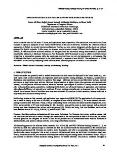
Fig. 1. Violations vs. variability factor.
Similarly, a high upper bound cost could result in higher duration of synchrony. Therefore, it is desired to have minimum violations while maintaining a low upper bound cost. 4.2. SyncProbe-synchrony As a first step in evaluation, we assessed the capability of SyncProbe in providing soft real-time guarantee of synchrony. We computed two metrics: (1) rate of violations, and (2) duration of synchrony. For rate of violations, we computed the percentage of probes for which the measured latency exceeded the upper bound during the 24-h period. We noted that the rate varies with the variability in latency. For three paths that have low standard deviation and low variability in latency, SyncProbe did not observe any violation. On the other end, for paths with higher variability in latency, SyncProbe maintained a higher upper bound cost in order to reduce violations. The highest rate of violations encountered is only 0.04%. On average, SyncProbe experienced 3.27 violations per path per hour, a 99.98% level of correctness. Table 2 shows the rate of violations for each path. While continuous probing and the EWM approach for upper bound estimation detect changes in latency and avoid violations, an abrupt and rapid increase in latency can still cause violation. A rapid increase in the latency also raises the variability factor. We analyzed the behavior of seven paths (that experienced violations) with respect to variability in latency. By dividing 24-h duration of measurements into small five minute intervals and computing the number of violations and variability factor during them, we noted that SyncProbe was capable in keeping low violations during the periods of high variability factor. For instance, for the two paths involving the node in Australia, SyncProbe only encountered violations, when the variability factor becomes greater than 12. Fig. 1 shows the relationship between average number of violations and variability factor.
J. Shamsi, M. Brockmeyer / J. Parallel Distrib. Comput. 72 (2012) 70–82
75
Fig. 2. Duration of synchrony. Fig. 4. SyncProbe adaptability.
during the two-hour period. The figure confirms that SyncProbe continuously adjusts the upper bound with respect to changing network behavior. The adaptability of SyncProbe is also evident from the variation in the monitoring interval (Table 2), in which paths with very low variability in latency has an average interval of 200 ms. Similarly, for the two paths involving node in Australia, which experience high packet loss and variability, the average interval is 155 ms. 4.5. Recoverability Fig. 3. Violations vs. upper bound cost.
We computed the cumulative distribution function (CDF) for duration of synchrony for all the paths. Fig. 2 shows the results in which the x-axis shows the categories for duration of synchrony on a logarithmic scale, where as y-axis represents the CDF, for each category. Each path is represented by a separate line, where as for the three paths with no violation, the three lines are overlapped and are seen as a single line. Note that a large portion of the total duration of synchrony consists of long durations that are separated by small periods of asynchrony. These results confirm the capability of SyncProbe in providing communication for Internet paths. 4.3. Upper bound cost A high value of upper bound would avoid most of the violations but would result in low system performance. Upper bound cost is the absolute difference between the upper bound and the measured latency, represented as the percentage of the measured latency. The relationship between upper bound cost and variability factor is illustrated in Fig. 3 where upper bound cost for the seven paths that encountered violations is plotted vs. variability factor. The figure confirms the ability of SyncProbe in adjusting the upper bound as per the path behavior. For paths with low variability, SyncProbe avoided any violation, while maintaining a low upper bound cost, whereas for paths with high variability, SyncProbe required higher upper bound cost in order to reduce violations. 4.4. SyncProbe adaptability Adaptability confronts with the capability of SyncProbe in adjusting itself to network conditions i.e. variability factor, violations, and packet loss. SyncProbe is highly adaptive to network behavior. Fig. 4 shows a sample scenario for two-hour duration for the de-uk path. The x-axis represents small durations of fiveminute intervals, whereas the y-axis (left) represents average upper bound and latency. The variability factor is represented on the secondary y-axis (right). The system experienced six violations (shown as stars) and three lost packets (shown as ovals)
Recoverability or responsiveness is measured with respect to settle time (the time required by the system to recuperate on the occurrence of a violation), where a low settle time implies a high recoverability. High agility is required in order to be responsive to variable network conditions. The responsiveness of SyncProbe is dependent on its monitoring interval i.e. SyncProbe generally responded quickly enough to a violation to bring the system back into compliance by the next probe. Table 2 shows the average settle time of the SyncProbe. Therefore, paths with low congestion generally have a high monitoring interval and have higher settle time. Similarly, for paths with higher variation in the latency, settle time is low due to the low monitoring interval. Above results confirm the ability of SyncProbe in providing predictable and bounded communication to Internet paths and achieving the aim of bounded communication. The next step in this research is to utilize assurance form path level to construct QoScompliant overlay networks with predictable communication. 5. QoSMap-overlay construction and management The QoSMap module fulfills two major aims of PSON: (1) constructing overlay networks according to topological specifications and QoS requirements of an application, and (2) enhancing QoS of the constructed overlay and ensuring that the overlay remained QoS-compliant. Of these two goals, the former is achieved by efficiently constructing the overlay on an Internet substrate, whereas the latter is accomplished through overlay routing such that overlay routes which enhance QoS are selected. Since path characteristics are not constant and may vary over time, updated information about overlay paths is computed through the network information provided by the SyncProbe module. In order to provide high QoS and maintain QoS-compliance, the constructed overlays are continuously monitored for QoS violation—a scenario in which either the upper bound of a path in an overlay exceeds an application’s acceptability limit or when the rate of violations of upper bound (message latency exceeding upper bound) becomes intolerable for an application. In both the cases, upon occurrence of QoS violation, the QoSMap module recomputes the overlay, so that the requirements of an application are met.
76
J. Shamsi, M. Brockmeyer / J. Parallel Distrib. Comput. 72 (2012) 70–82 Table 3 QoSMap: goals and features. Goal
Heuristics
Increasing QoS
- Limit the number of hops for hop-degrading QoS metrics - Include QoS-compliant backup paths which can be utilized when primary paths are QoS-incompliant - Incorporate fail aware reconfiguration
Increasing lifetime
The purpose of this section is to describe and explain the approach of QoSMap in fulfilling these two challenges. We first explain the problem of overlay construction related to the domain of QoS-compliance and predictable communication. This is followed by the approaches and mechanisms adopted by QoSMap and the algorithms it implements to achieve these two goals. 5.1. Overlay construction and management The overlays are constructed with two specific goals: (i) Increasing QoS, and (ii) Enhancing resilience against QoS failures. (1) Increasing QoS: Quality of Service is measured according to an application’s constraints. Each constraint is specified as a tuple, ⟨R, W ⟩ in that R denotes the requested value of the constraint and W indicates its associated weight. The quality of a path is represented as M and can be computed as M =
n − Pi i =1
Ri
wi
(1)
where, M represents the ratio of the QoS received by an application over the QoS requested. Pi denotes the actual value of the constraint i for a given path, and Σ wi = 1. We assume that each Pi is increasing, that is, the application favors high values of the metrics. Note that the above equation describes a generalized concept for measuring QoS. For the problem of providing predictable communication, application’s constraints of upper bound (maximum expected latency) and the rate of violations (rate at which bounded communication is violated) are considered. Eq. (1) shows QoS at a particular instance. In order to compute QoS over a period of time, QoS during each time interval is computed and averaged to obtain overall QoS. (2) Enhancing resilience: Resilience indicates the capability of the constructed overlay to tolerate variable network behavior that could violate an application’s QoS constraints. It is measured in terms of lifetime, which is the duration from overlay formation to the instance of QoS failure, such that the overlay must be reconfigured. Note that the notion of lifetime of overlay is similar to the notion of duration of synchrony in SyncProbe in the context that the violation of upper bound in SyncProbe leads to an asynchronous period and termination of synchronous activity, whereas, the QoS incompliance for an application’s constraints (upper bound and rate of violations) results in reconfiguration of an overlay and marks the end of its lifetime. In presence of dynamic network behavior it is a severe challenge to construct and manage overlay such that it meet an application’s stringent QoS requirements of bounded latency and rate of violations. 5.1.1. Optimal solution of overlay construction Finding an optimal overlay requires that both the QoS and lifetime, are maximized. However, the two metrics are not necessarily correlated. For instance, an overlay which provides high QoS does not necessarily provide high lifetime. In order to compute an optimal solution for QoS, we define the term Quality Index (QI), which is computed as the ratio of sum of QoS (M) over the Coefficient of Variation (Cv) of QoS for all the
paths in the overlay. For an overlay with q paths, the quality index can be represented as q ∑
QI =
Mk
k=1
1 + cv
.
(2)
The use of sum over coefficient of variation ensures that the effect of overlays which has only few paths with a very high value of QoS is normalized, where as ‘1’ is added in the denominator to reduce the effect of a very small value of coefficient of variation. The optimal solution is the solution with the maximum QI. Note that the above equation denotes quality at a particular instance. For instance, for the problem of constructing QoS-optimized overlay, the equation denotes the quality index at the time of overlay formation. In comparison to the QoS-optimized solution which can be computed at the time of overlay formation, the construction of lifetime-optimized overlay would require computing the lifetimes of all the possible overlays. However, lifetime is based on the network failures in the future, and therefore cannot be computed at the time of overlay construction. Therefore, we only consider optimal solution for QoS-optimized overlay. However, QoSMap implements techniques to enhance overlay lifetime. 5.1.2. Complexity of overlay construction Computing the optimal solution or the overlay construction problem is NP-hard, since the problem can be represented as the graph embedding problem [18]. The process of computing optimal solution involves calculating all the possible paths between any two pair of nodes to determine the optimal path (the path with highest QoS), and then using the optimal paths to compute quality index (QI) for all the possible overlay configurations. For an overlay configuration problem with n nodes in the underlay and m nodes in the overlay, the number of possible overlay configurations is (n−n!m)! , which is O( (n−n!m)! ). Since n ≥ m, the complexity can be simplified to C = O(n).
(3)
5.2. The QoSMap approach QoSMap incorporates three techniques to compute overlays that provide high QoS and increased lifetime. For efficiency, QoSMap adapts three heuristics for achievement of these goals. We now describe these techniques. Table 3 shows the relationship between the goals of QoSMap and the heuristics adapted by it. (1) Goal 1: Achieving high QoS: The complexity for the optimal solution (Eq. (3)) is high because, for an overlay path, a large number of possible solutions exist, amid no restriction on the number of underlay hops in an overlay path. However, since the focus of this research is on hop-degrading QoS metrics (upper bound estimates and its rate of violations) in that each additional underlay hop in an overlay path decreases the overall quality of the path, it makes sense to restrict the number of underlay hops in an overlay path. This is because including a large number of underlay hops in an overlay path would increase the value of the metric such that QoS may be violated or reduced. Note that a path with fewest
J. Shamsi, M. Brockmeyer / J. Parallel Distrib. Comput. 72 (2012) 70–82
underlay hops does not always provide shortest path as triangle inequality principle does not hold on the Internet [38]. For instance, for an overlay with triangle topology ABC, if AB = 100 units, CB = 25 units, and AC = 50 units, then the indirect path from node A to node B (via node C) would be a shorter path. However, given the relative rarity of this situation, it makes sense to limit the number of underlay hops. Due to this reason, QoSMap computes short overlay paths comprised of a limited number of underlay hops (QoSMap-LH) such that each computed path meets application QoS constraints and promotes high quality. This facilitates high QoS in computed overlays. In order to determine the number of hops required to compute high quality paths, we performed an evaluation and observed that paths with up to two intermediate nodes should be considered in overlay construction for improved QoS while paths longer than three hops do not really contribute in improving QoS. We implemented paths up to two intermediate underlay nodes in our implementation of QoSMap. Note that QoSMap adopts this heuristic to reduce the complexity of overlay construction as we expect that paths with longer than three PlanetLab (underlay) hops are very much less likely to provide higher QoS than the paths with fewer hops. We anticipate that this analysis will hold for other PlanetLab-like platforms. (2) Goal 2: Increasing lifetime: Achieving high resilience over vibrant Internet is a severe challenge, specifically when the goal is to provide predictable communication. In order to meet this challenge QoSMap adopts two techniques. (a) Backup paths: In addition to constructing overlay topology desired by an application, QoSMap computes QoS-compliant back up paths (QoSMap-B). A back up path is used when the primary path between two nodes violates an application’s QoS constraints and the backup path is still QoS-compliant. In order to construct backup paths QoSMap may require additional intermediate nodes. However, in order to reduce the cost of such nodes, QoSMap prefers to use nodes which are already included in the overlay either as mapped overlay nodes or intermediate overlay nodes for an already constructed backup path. The use of back up paths extends overlay lifetime such that the overlay is reconfigured if a primary path and all of its back paths violates QoS. (b) Fail-aware reconfiguration: In order to increase lifetime QoSMap also adopts fail-aware reconfiguration (QoSMap-FA). In that, during the process of overlay reconfiguration, QoSMap gives low priority to nodes that have caused QoS failure. QoSMap implements a node failure detection algorithm, which determines the nodes that have caused QoS violation.
4. 5. 6. 7.
77
b. The average number of backup paths a node provides, capped at two. c. Preferring nodes that have already been included as intermediate nodes for indirect paths. d. Quality of a node which is computed by calculating the average quality over all the outgoing and incoming paths. From the sorted Node-list, select the next available underlay node and map it as the overlay node. From the Path-list, compute the primary and the backup paths, where primary path is the path with the highest QoS. If no underlay node exists satisfying the degree requirements of the overlay node then backtrack. Repeat the algorithm (Step 2) until all the overlay nodes are mapped, or until no solution exists.
5.3.2. Failure-detection algorithm Upon occurrence of a QoS violation leading to overlay failure, QoSMap uses the following algorithm to identify nodes that have caused QoS failure. 1. Upon failure of a primary path, compute the failure-weight (F ) for both the source and destination nodes of the path. The failure-weight of a node (j) is computed as follows: Fj =
Failed_pathsj Total_pathsj
.
(4)
2. While determining failure weight, the information is obtained at the underlay level. That is, for Eq. (4), the total number of paths corresponding to the node j that initially satisfied the application’s QoS constraints (not just the paths mapped in the overlay) are used for the denominator. Similarly, the total number of failed paths (corresponding to node j) that encounter QoS violations at the time of failure is considered for the numerator. 3. The information is computed according to the node’s involvement as a source or destination node of a path. That is, if a node is the source node of the failed path, then the egress paths are considered; similarly, if a node is the destination node of the failed path, then the ingress paths are utilized. In this manner, two separate lists of failed nodes, one each for the source and the destination nodes for the failed paths are computed. 4. Once the failure-weights are computed, nodes are selected from the egress or ingress list based on their failed-weights such that a relevant node with the highest weight is elected from either the egress or ingress list for each failed path. The three techniques of QoSMap i.e. QoSMap-LH, QoSMap-B, and QoSMap-FA yields efficient overlays that provide high QoS and long lifetime to applications expecting predictable communication. QoSMap relies on efficient monitoring and immediate availability of network characteristics, which is provided by SyncProbe.
5.3. QoSMap algorithms 6. QoSMap-evaluation We now explain the two algorithms of QoSMap. The first algorithm explains the overlay construction technique in detail, whereas the second algorithm describes the mechanism to identify the faulty node in the system. 5.3.1. Overlay construction Given an overlay request and an underlay network, the main steps of the QoSMap algorithm are explained below. 1. Compute all the direct, 2-hop and 3-hop QoS compliant paths (Path-list). 2. Select an unmapped overlay node with the highest degree (number of ingress and egress edges). 3. Prepare a list (Node-list) of underlay nodes that fulfills the degree requirements of the selected overlay node. Sort the list as follows: a. Prioritize nodes that do not observe QoS violations, recently.
We evaluate the ability of QoSMap to provide predictable communication for applications with strict requirements of upper bound and its violations. For this purpose, we seek network measurements from a large set of PlanetLab nodes in order to manage overlay networks more efficiently and evaluate QoSMap rigorously. 6.1. Experimental setup We deployed SyncProbe on 20 PlanetLab hosts and estimated upper bound on latency between all pairs of endpoints, yielding an underlay network of 380 paths. We focused on selecting nodes that can provide a diverse set of paths, including paths between educational and industrial sites and inter-continental routes. The total duration of our experiments was approximately 30 h. The monitoring interval was varied between 100 and 2000 ms.
78
J. Shamsi, M. Brockmeyer / J. Parallel Distrib. Comput. 72 (2012) 70–82
6.1.1. QoS and topology requirements We varied an application’s requirements of overlay topology and QoS constraints in order to evaluate the performance of QoSMap under differing network conditions. The upper requirements were varied to 100, 150, 200, 250, and 300 ms, whereas the acceptability requirement for violations was fixed to 0.05%. This is because in our experiments we did not observe much variation in violations as SyncProbe rapidly adjust upper bound in case of abrupt network behavior. All of the QoS-failures occurred when upper bound exceeded an application’s threshold limit. Note that since QoSMap filters out all paths which do not provide the meet required constraints, the result is an underlay substrate that is less connected for applications which have more stringent latency bound requirements. We also considered five different overlay topologies of eight nodes: a completely connected overlay (clique), randomly connected overlays with 50% and 25% connectivity, a tree topology and a ring topology. Overall, the combination of five QoS latency upper bound requirements and five topology requirements yielded 25 different application overlay requests. 6.1.2. Evaluation criteria The major aim of evaluation was to assess the capability of providing predictable communication and meeting two goals of achieving high QoS and providing longer lifetime. For performance comparison, we used a simple QoS scheme for overlay construction, which although constructs QoS-compliant overlays but does not any implement of the three features of QoSMap (i.e., intermediate nodes in the overlay path, explicit construction of backup paths, and fail-aware node selection). Instead, the simple QoS scheme only considers direct underlay paths for overlay mapping, relies only on backup paths which are incidentally created during construction, and ignores information about previous node failures. 6.1.3. Computing overlays We divided the 30-h duration of our experiment into oneminute intervals and computed a moving average of the latency bound and violations for each interval. The moving average allowed us to smooth the path behavior over time. A gain of 0.5 was used to calculate the moving average, so that recent snapshots are weighted highly and older snapshots are aggressively aged. Once a request for overlay construction is received, each construction scheme (QoSMap or the simple QoS) tries to find a suitable match in the underlying network. Initially, for overlay construction, the snapshots of the path at the instance of arrival of application request were considered to compute QoS-compliant overlay networks. Note that the existence of a QoS-compliant overlay is not guaranteed due to underlying network conditions. QoSMap may occasionally report failure to an application if no possible combination exists in which the underlying network meet an application’s constraints. During our experiments, we noted that for the clique topology an overlay request cannot be fulfilled when the maximum latency bound requirement was 100 ms. 6.2. QoSMap-goals and features The first goal of our evaluation was to assess the contribution of the three features of QoSMap i.e. QoSMap-LH, QoSMap-B, and QoSMap-FA in accomplishing its two goals of achieving high QoS and increasing lifetime. The contribution of limited hops is to attain high QoS, while backup paths and fail-aware reconfiguration contributes to increasing overlay lifetime. In order to compare the effectiveness of the three features of QoSMap, we deployed them in an incremental manner.
Fig. 5. Upper bound averaged over all topologies.
Fig. 6. Lifetime averaged over all topologies.
QoSMap-LH: QoSMap scheme with limited number of hops (up to two intermediate nodes) as the primary paths. This scheme does not compute backup paths for overlays and it ignores previous node failures when re-configuring the overlay networks. QoSMap-LH + B + FA: This is the complete QoSMap scheme with all the three features, i.e., compute primary paths with limited hops, compute QoS-compliant backup paths and implement fail-aware node priority scheme for reconfiguration. We compared QoSMap with these three schemes to the simple QoS scheme which does not implement any of these three features. Using upper bound and longer lifetime as the metrics, we observed that the three schemes performed substantially better than the simple QoS scheme and meet their respective rationales in improving the overall performance of the QoSMap. We observed that by allowing limited number of hops, the QoSMap-LH scheme considerably reduces the latency upper bound (enhances quality) as compared to the simple QoS approach. We also noted that by adding backup paths, the QoSMap-LH + B scheme significantly extends the lifetime of the mapped overlays. The effect of the fail-aware node priority method during reconfiguration was also noteworthy. The QoSMap-LH + B + FA scheme outperforms all the other schemes with respect to the lifetime. Figs. 5 and 6 illustrate the upper bound and the lifetime of the mapped overlays yielded by all the four schemes. The results are averaged over the five topologies. It is evident from the figures that the three features of QoSMap achieve their respective goals in improving the performance of the mapped overlays. We also performed statistical evaluation to compare the performance of the four schemes and noted that the results are statically significant with respect to our observations mentioned above. Table 4 summarizes the statistical significance and the p values. Since the QoSMap with all the three features (QoSMapLH + B + FA) provides the best performance with respect to low latency bound and long lifetime, we selected it as the QoSMap approach and use it for further evaluation.
J. Shamsi, M. Brockmeyer / J. Parallel Distrib. Comput. 72 (2012) 70–82
79
Table 4 Statistical significance-P values simple QoS and features of QoSMap. Feature
Statistical significance P-value
Simple QoS QoSMap-LH QoSMap-LH + B QoSMap-LH + B + FA
Latency bound
Lifetime
– 0.000 N.S. N.S.
– N.S. 0.000 0.001
N.S. = Not Significant.
Fig. 9. Lifetime simple QoS.
Fig. 7. Upper bound—simple QoS.
Fig. 10. Lifetime QoSMap.
Fig. 8. Upper bound—QoSMap.
6.3. QoSMap vs. simple QoS As a second step, using QoS (upper bound) and lifetime as metrics, we compared the performance of QoSMap approach with simple QoS. Figs. 7 and 8 show the upper bound of the overlays generated by the simple QoS and QoSMap schemes, respectively with all the five topologies. The bound on latency for the simple QoS is higher than the bound of QoSMap. Further, the variation in bound (over five topologies) increases as the QoS constraints exceed 200 ms. In comparison, the bound provided by the QoSMap is significantly lower and has less variation over the different topologies. With respect to lifetime, we observed that except for the clique topology, all the rest of the topologies result in very low lifetimes for the simple QoS scheme (Fig. 9). For the clique topology, the simple QoS scheme resulted in long lifetimes due to the existence of backup paths which were found in the overlay due to high connectivity. Note that although the simple QoS scheme does not explicitly construct backup paths, we checked for the existence of such paths, if they happen to be found in the mapped overlay. In comparison, for the QoSMap scheme, the lifetimes of computed overlays were substantially higher for all the topologies (Fig. 10). The average lifetime increases with the relaxation in the QoS requirements and approached 360 min when the latency bound requirement was 300 ms.
Fig. 11. Cost of backup paths.
6.4. Cost of backup paths Backup paths contribute to increased lifetime of the overlay; however, QoSMap may require additional nodes in order to construct them. The cost is computed as the ratio of the number of total nodes provided to the application (including additional nodes for backup paths) over the number of nodes needed by the application. We observed that over all QoSMap only requires very few additional nodes to provide backup paths (Fig. 11). The number of additional nodes decreases with the relaxation of the QoS requirements as QoSMap was able to find nodes that can be used to both to provide backup paths and mapped as overlay nodes at the same time. Overall, the cost ratio varies between 1.25 and 1.0, which shows the strength of QoSMap in constructing backup paths without requiring many additional nodes. 6.5. Overlays without reconfiguration We also evaluated the usefulness of QoSMap for real-time applications that cannot accommodate the down-time associated with overlay reconfiguration. We used the two overlay mapping schemes to construct overlays. However, instead of reconfiguring the overlay upon QoS failure, the overlays were examined to
80
J. Shamsi, M. Brockmeyer / J. Parallel Distrib. Comput. 72 (2012) 70–82
Fig. 12. Upper bound simple QoS (without reconfiguration).
Fig. 13. Upper bound QoSMap (without reconfiguration).
Fig. 15. Success rate QoSMap (without reconfiguration).
are much higher, with the lowest rate of 80% for the ring topology (Fig. 15). Further, for the QoSMap scheme, the success rate over all topologies increases and becomes constant to 97.5%, when the bound requirements are relaxed to 200 ms or higher. We also compared QoSMap with the optimal overlay scheme with respect to quality index (Eq. (2)) and execution time. We noted that QoSMap computes overlays with quality index which is at least 90% of the quality index of the optimal overlay scheme. However, with respect to execution time, the optimal scheme has a very high complexity. The execution time of the optimal scheme was up to 106 times of that of QoSMap. Our observations assert the strength of QoSMap in computing overlays with high QoS in a timely manner. The above results confirm the effectiveness of QoSMap in providing predictable communication for applications that prefers to avoid reconfiguration due to high cost of redeployment. 7. Related work PSON is inspired by substantial previous work in bounded message communication, enhanced QoS, and mapping on Internet substrates.
Fig. 14. Success rate simple QoS (without reconfiguration).
determine when the network condition improved and the overlay again demonstrated real-time behavior. We computed the latency bound provided and observed that simple QoS provides a looser upper bound on latency (Fig. 12) when compared to the latency bound provided by QoSMap (Fig. 13). We also observed that the latency bound provided by simple QoS observe high variation over different QoS and topology requirements. We also computed the success rate for the two schemes which is computed as the percentage of the amount of time the overlay remains QoS compliant during the total duration of the experiment (30 h). We observed that overlays yielded by simple QoS (Fig. 14) observe large variability in the success rate and has the lowest success rate of only 30%. In contrast, the success rates for the QoSMap schemes are much higher, with the lowest rate of 80% for the ring topology (Fig. 15). Further, for the QoSMap scheme, the success rate over all topologies increases and becomes constant to 97.5%, when the bound requirements are relaxed to 200 ms or higher. We also computed the success rate for the two schemes which is computed as the percentage of the amount of time the overlay remains QoS compliant during the total duration of the experiment (30 h). We observed that overlays yielded by simple QoS (Fig. 14) observe large variability in the success rate and has the lowest success rate of only 30%. In contrast, the success rates for the QoSMap schemes
Bounded message communication Need for bounded and synchronous communication has been discussed by many researchers. In [16], the authors presented various models of partial synchrony, which exists if communication bound is established for some duration. In [10], the authors introduced programming model for distributed systems incorporating partially synchronized systems. Later, Ezhilchelvan and Shrivastava presented design approaches [17] to avoid complications resulting from lack of consensus in an asynchronous system. Similarly, Aguilera and Walfish [3] described significance of timing guarantees for distributed systems. Inspired by implications of asynchronous systems, they proposed a perfect failure detector model, which deviates from the conventional asynchronous model. Similarly, Abraham et al. [1] presented randomized algorithms for consensus in asynchronous systems. They considered systems in which minority process can experience crash, omission, and Byzantine failures. PSON is supplemental to the above mentioned approaches. PSON is inspired by the need of establishing synchrony among communication nodes in wide area networks. For this purpose, it employs robust and effective mechanisms to estimate communication bound on network paths, which vary according to network behavior. The bound provided by PSON can be utilized by many applications to achieve consensus or detect failures. In another work, Cristian and Fetzer [14] proposed and validated a timed asynchronous model for local area networks. The model implements timed communication and responses through an un-reliable datagram service. PSON is inspired by their model [14]. However, in comparison of achieving synchrony
J. Shamsi, M. Brockmeyer / J. Parallel Distrib. Comput. 72 (2012) 70–82
on a local network and maintaining a fixed bound on each path, it is focused on estimating bounded latency for Internet paths. Therefore, instead of maintaining a fixed bound for all the paths, it employs an agile and robust mechanism to adjust the bound according to the behavior of each network path. For this purpose, it incorporates efficient monitoring and network estimation techniques in order to respond to changing network conditions in an efficient manner. Quality of service: Mechanisms to provide QoS have been popularly deployed using overlay networks. These solutions bear lower cost as compared to network based solutions such as Diffserv [6] and MPLS [39]. OverQoS [37] provides specific QoS services such as packet prioritization and statistical loss and bandwidth guarantees to applications. Service overlay networks (SoN) [15] purchase bandwidth guarantees from ISPs in the form of SLAs to build an overlay that can provide end-to-end QoS guarantees. In contrast, the notion of QoS provided by PSON is different, in that, it provides stringent guarantees of bounded latency and its violations to an application. Further, PSON provides continuous QoS guarantees rather than amortizing QoS over a longer window as OverQoS does. In addition, PSON is an application-layer solution in which it does not require SLAs or other special services from the ISPs. QRON [24] utilizes special purpose nodes called overlay brokers (OB) to form overlay service networks that provide support for resource allocation and negotiation, overlay routing, and topology discovery. Our work is similar in that it utilizes dedicated routes which are constantly updated to meet the expectations of predictable communication. Further, in PSON, the supplemental paths are utilized only upon the failure of primary paths and thus improve the resilience against QoS failure. QoSMap strives to reduce the number of additional nodes needed by utilizing them as overlay nodes. A significant difference between PSON and all the other work mentioned above is that PSON is designed to meet stringent QoS requirements of predictable communication. Due to these strict requirements, it incorporates efficient mechanisms for monitoring, overlay construction, and routing. PSON’s idea of utilizing backup paths upon QoS failure of primary paths is inspired by RON [5] and Detour [32], which use backup paths to overcome network outages. However, RON does not construct overlay networks nor does it provide QoS requirements. Instead, it utilizes the indirect route if the direct route becomes unavailable due to network outage. Further, the focus of QoSMap is on meeting stringent QoS requirements (bounded communication) in dynamic network conditions and reducing cost of overlay reconfiguration rather than on overcoming network outages. Huang et al. proposed an overlay scheme to achieve bounded latency among overlay nodes that are utilized as servers for a Content Distribution Network (CDN) [22]. The overlay mapping problem is considered as a graph domination problem in which each node is required to have a minimum set of nodes reachable within the bounded latency. The model requires high bandwidth servers for static latencies. In comparison, QoSMap incorporates dynamic network behavior and does not require additional ISP support. Researchers have also focused on enhancing application performance through topological aware overlay construction [29,35] and tactical node placements [31]. While, tactical construction increases the efficiency of the overlay networks, it is mainly focused on maintaining good connectivity among the overlay nodes and minimizing message delay in the network. Contrary to that, our work is focused on computing user-specific overlay topology which can meet the stringent requirements of hop-degrading QoS metrics—a task which is not addressed by topological aware overlays. Additionally, QoSMap specifically constructs QoS-compliant
81
backup paths in order to ensure that the overlay meets application’s QoS criteria during QoS-failure of the primary paths. Overlay construction on the internet substrate Another major service provided by PSON is to construct overlays on the Internet according to the topological and QoS requirements of an application. Zhu and Ammar [42] describe a virtual network (VN) assignment solution which reduces link and node stress in the underlying network. Their solution focuses on balancing load on substrate nodes and links, and does not impose any restrictions on the number of hops in computing the end-to-end overlay path. As a result, we do not expect that their approach will satisfy applications having stringent requirements on hop-degrading QoS metrics. SWORD [28] is a resource discovery scheme for Internet substrates such as PlanetLab. The users request a desired topology along with the node and link-based characteristics such as CPU usage, latency and bandwidth. Similarly, MoN [23] is an overlay construction tool for PlanetLab. It builds on demand overlays which do not provide resilience against QoS failures. QoSMap is different than the two schemes as it employs heuristics to achieve high QoS and longer lifetime. It not only limits the number of underlay hops in an overlay path, but also computes backup paths and implements the node priority scheme to increase resilience against QoS failures. Yu et al. [41] presents the idea of providing substrate support for embedding virtual networks. They proposed path splitting (flexibly splitting path according to the bandwidth capacity of each split path) and path migration (migrating paths in order to accommodate dynamic VN requests). Our work is similar in the context that our backup paths enable and enhance path migration. However, instead of relying on the existence of ad-hoc paths to perform path migration, we explicitly construct backup paths to utilize them upon QoS violation of primary paths. Path splitting is infeasible for QoSMap as we consider hop-degrading QoS metrics which cannot be achieved by combining paths in parallel. Banarjee et al. present a decentralized algorithm to address the problem of ‘‘degree constrained minimum average latency’’ for real-time multimedia applications [7]. The algorithm iteratively modifies the overlay tree to adapt with changing client distributions and network conditions. Similarly, Houidi et al. [21] present their solution for the assignment of virtual networks, in which they focused on decentralization and atomicity through multi-agents. Contrary to these efforts, our work is based on developing on heuristics to achieve high QoS and long lifetime and it is directed towards the applications having constraints of hop-degrading QoS metrics. 8. Conclusion and future work The three contributions of PSON make it a distinctive infrastructure of providing predictable communication with bounded message latency at the application layer. PSON is based upon capable management of resources in the underlay network in order to mask the associated unpredictable behavior and built an application network which meets the predictability criteria of an application. PSON is aided by SyncProbe, which monitors underlay paths in order to measure network information and estimate bounded latency along network paths. SyncProbe is highly adaptive and manageable. It adjusts the probing rate according to network state of each path. Further, it varies the bound on latency according to the network condition. PSON also incorporates QoSMap, which utilizes network information to identify resources to form an overlay with desired QoS of bounded latency and network topology. The QoSMap module utilizes intelligent management approaches
82
J. Shamsi, M. Brockmeyer / J. Parallel Distrib. Comput. 72 (2012) 70–82
including constructing short and efficient overlay paths, computing QoS-compliant backup paths, and employing fail-aware reconfiguration of overlay to achieve bounded communication and extended overlay lifetime. PSON operations and management is supported by robust network aggregation and exchange mechanisms in which application nodes contribute to PSON routing and promote predictability and by the PSON API which provides useful interaction to an application availing PSON benefits. The assurance of bounded communication provided by PSON could be beneficial to many applications, which require predictable communication on the volatile Internet. Consequently, applications such as multimedia VOIP, Internet gaming, and distributed simulation would experience improved performance. Many distributed problems, such as consensus and leader election [2], which are not solvable due to absence of bounded communication, would be solvable with PSON. Additionally, distributed predicate detection [9] can also avail the benefits of predictable service overlay networks. PSON could also be useful for many emerging applications such as cloud computing applications [40], which can utilize the communication predictability of PSON to provide enhanced reliability. Acknowledgments The authors are thankful to National Science Foundation for funding this project and to the anonymous reviewers who helped in improving the quality of the paper. References [1] I. Abraham, M.K. Aguilera, D. Malkhi, Fast Asynchronous Consensus with Optimal Resilience, The 24th International Conference on Distributed Computing, 2011. [2] M.K. Aguilera, C. Delporte-Gallet, H. Fauconnier, S. Toueg, Communicationefficient leader election and consensus with limited link synchrony, The 23rd annual ACM symposium on Principles of distributed computing (PODC) 2004. [3] M.K. Aguilera, M. Walfish, No time for asynchrony, ACM Hot OS (2009). [4] S. Aki, S. Beruda, Improving a solution’s quality through parallel processing, Journal of Supercomputing 19 (2) (2001) 221–233. [5] D. Andersen, H. Balakrishnan, M. Kaashoek, R. Morris, Resilient Overlay Networks, Proc. 18th ACM SOSP, Banff, Canada, October 2001. [6] A. Bandara, E. Lupu, A. Russo, N. Dulay, M. Sloman, P. Flegkas, M. Charalambides, G. Pavlou, Policy refinement for diffserv quality of service management, IEEE Transactions on Network service Management 2 (2) (2006). [7] S. Banerjee, C. Kommareddy, K. Kar, B. Bhattacharjee, S. Khuller, OMNI: an efficient overlay multicast infrastructure for real-time applications, in: Computer Networks, Elsevier, 2006. [8] A. Bavier, M. Bowman, B. Chun, D. Culler, S. Karlin, S. Muir, L. Peterson, T. Roscoe, T. Spalink, M. Wawrzoniak, Operating system support for planetaryscale network services, USENIX NSDI (2004). [9] M. Brockmeyer, C. Chu, An Internet-Scale Monitoring and Assertion Checking Infrastructure, The 23rd annual ACM symposium on Principles of Distributed Computing PODC, page 389, July 2004. [10] S. Chaudhri, R. Gawlick, N. Lynch, Designing Algorithms for Distributed Systems with Partially Synchronized Clocks, The 12th ACM symposium on Principles of Distributed Computing (PODC), August 1993. [11] Y. Chen, D. Bindel, R. Katz, Tomography based overlay network monitoring, IMC (2003). [12] M. Claypool, The effect of latency on user performance in real-time strategy games, in: Computer Networks, in: Computer Networks, vol. 1, Elsevier, 2005, pp. 52–70. [13] E. Corell, P. Saxholm, D. Veitch, A user friendly TSC clock, Passive and Active Measurements Workshop 2006. [14] F. Cristian, C. Fetzer, The timed asynchronous distributed system model, IEEE Transactions on Parallel and Distributed Systems 10 (6) (1999) 642–657. [15] Z. Duany, Z. Zhangy, Y. Hou, Service overlay networks: SLA, QoS and bandwidth provisioning, IEEE ICNP (2002). [16] C. Dwork, N. Lynch, L. Stockmeyer, Consensus in the presence of partial synchrony, Journal of the ACM 35 (2) (1988) 288–323. [17] P. Ezhilchelvan, S. Shrivastava, Learning from the past for resolving dilemmas of asynchrony, ACMG SIGOPS Review (2010). [18] F. Harary, Graph Theory, Addison-Wesley, 1971, Reading, Mass. [19] S. Harcsik, A. Petlund, C. Griwodz, P. Halvorsen, Evaluation of Networking Mechanisms in Game Traffic, in: The 6th Annual Workshop on Network and Systems Support for Games: Netgames 2007.
[20] Y. He, I. Ahmed, M. Liou, Mpeg-4 based interactive video using parallel processing, in: International Conference on Parallel Processing, ICPP’98. [21] I. Houidi, W. Louati, D. Zeghlach, A distributed virtual network mapping algorithm, in: IEEE International Conference on Communications, ICC, 2008. [22] C. Huang, T. Abdelzaher, Bounded-latency content distribution: feasibility and evaluation, IEEE Transaction on Computers 54 (11) (2005) 1422–1437. [23] J. Liang, S.Y. Ko, I. Gupta, K. Nahrstedt, MON: on-demand overlays for distributed system management, USENIX WORLDS 05. [24] Z. Li, P. Mohapatra, QRON: QoS-aware routing in overlay networks, IEEE Journal of Selected Areas of Communication 22 (1) (2004) 29–40. [25] J. Liu, S.G. Rao, B. Li, H. Zhang, Opportunities and challenges in peer to peer internet video broadcast, IEEE Special Issue on Recent Advances in Distributed Multimedia Communications 96 (1) (2008) 11–24. [26] H. Madhyastha, T. Isdal, M. Piatek, C. Dixon, T. Anderson, A. Krishnamurth, A. Venkataraman, iPlane: an information plane for distributed services, OSDI (2006). [27] D. Mills, Internet time synchronization: the network time protocol, Transactions on Communications 39 (10) (1991) 1482–1493. [28] D. Oppenheimer, B. Chun, D. Patterson, A.C. Snoeren, A. Vahdat, Service placement in a shared wide-area platform, in: Usenix Annual Technical Conference, 2006. [29] S. Ratnasamy, M. Handley, R. Karp, S. Shenker, Topologically-aware overlay construction and server selection, IEEE INFOCOM (2002). [30] P. Rowe, VOIP extra threats in the converged environments, Elsevier Network Security (7) (2005) 12–16. [31] S. Roy, H. Pucha, Z. Zhang, Y.C Hu, L. Qiu, Overlay node placement: analysis, algorithms and impact on applications, IEEE ICDCS (2007). [32] S. Savage, T. Anderson, A. Aggarwal, D. Becker, N. Cardwell, A. Collins, E. Hoffman, J. Snell, A. Vahdat, G. Voelker, J. Zahorjan, Detour: informed internet routing and transport, IEEE Micro 19 (1) (1999) 50–59. [33] J. Shamsi, M. Brockmeyer, SyncProbe: providing assurance of message latency through predictive monitoring of Internet paths, in: The 10th IEEE High Assurance Systems Engineering Symposium, 2007. [34] J. Shamsi, M. Brockmeyer, QoSMap: achieving quality and resilience through overlay construction, in: The Fourth International Conference on Internet and Web Applications and Services, ICIW, Italy, May, 24–28 2009. [35] J. Shamsi, M. Brockmeyer, Tactical construction of overlay networks, IEEE Globecom (2005). [36] N. Spring, L. Peterson, A. Bavier, V. Pai, Using planetlab for network research: myths, realities, and best practices, ACM SIGOPS Operating Systems Review 40 (1) (2006) 17–24. [37] L. Subramanian, I. Stoica, H. Balakrishnan, R.H. Katz, OverQoS: an overlay based architecture for enhancing internet QoS, Usenix NSDI (2004). [38] G. Wang, B. Zhang, T. Ng, Towards network triangle inequality violation aware distributed systems, in: The Fifth Internet Measurement Conference, IMC, 2007. [39] X. Xiao, A. Hannan, B. Bailey, L.M. Ni, Traffic engineering with MPLS in the internet, IEEE Networks 14 (2) (2000) 28–33. [40] L. Youseff, M. Butrico, D. Silva, Toward a unified ontology of cloud computing, Grid Computing Environments Workshop, 2008, GCE’08, pp. 1–10. [41] M. Yu, Y. Yi, J. Rexford, M. Chiang, Rethinking virtual network embedding: substrate support for path splitting and migration, ACM Computer Communication Review 38 (2) (2008) 17–29. [42] Y. Zhu, M. Ammar, Algorithms for assigning substrate network resources to virtual components, IEEE INFOCOM (2006). [43] A.Y. Zomaya, Parallel processing for real-time simulation: a case study, IEEE Parallel and Distributed Technology: Systems and Applications 4 (2) (1996) 49–62.
Jawwad Shamsi received his Ph.D. degree in Computer Science from Wayne State University, MI, USA. He is currently an Assistant Professor at National University of Computer and Emerging Sciences, Karachi, Pakistan. His research interest lies in Overlay Networks, Network Monitoring, Security, High Performance Computing, and Cloud Computing.
Monica Brockmeyer received her Ph.D. degree in Computer Science from the University of Michigan—Ann Arbor. She is currently an Associate Professor and interim Chair of the Computer Science department at Wayne State University, Detroit, MI, USA. She is interested in Large Scale Distributed Systems, Cloud Computing Systems, and many challenges related to distributed computing such as Consensus, Replication, and Predicate Detection.