W. Marcum. 2. 1International Atomic Energy Agency, Austria. 2Oregon State University, USA. Abstract. The International Atomic Energy Agency (IAEA) organizes ...
Fluid Structure Interaction VII
179
Prediction of hydro-mechanical behaviour in a reactor core with a plate-type fuel assembly J. Choi1 & W. Marcum2 1 2
International Atomic Energy Agency, Austria Oregon State University, USA
Abstract The International Atomic Energy Agency (IAEA) organizes an International Collaborative Standard Problem (ICSP) on “Prediction of Hydro-Mechanical Behaviour in Reactor Core with a Plate-type Fuel Assembly” and invites the participation of interesting institutes from IAEA Member States. The experimental study will be conducted in the Hydro-Mechanical Fuel Test Facility in Oregon State University in the USA. The objective of the experiment is to identify the flow conditions which induce the onset of elastic plate deformation for fuel plate and to identify the flow conditions which produce plate failure of each fuel plate material. This experimental data may be utilized to assess multi-physics tools simulating the following phenomena: flow disparity within a fuel plate assembly, bulk computational thermal hydraulic characteristics, influence of pressure boundary condition on solid domain, and fuel plate plastic deformation and vibration. The participants from IAEA Member States will be able to use safety analysis codes and/or general computational multi-physics codes to perform blind and open simulations of the experiment. Through the ICSP, participants may identify any weaknesses or strengths of their prediction tools, search a way to overcome any limitations, and also suggest any further experiments or analytical models to fill the gap to be identified in the ICSP. Keywords: code validation, hydro-mechanical behaviour, ICSP, initial and boundary conditions, plastic deformation, plate-type fuel assembly.
1 Introduction The general purpose of the ICSP is to facilitate the development and validation of computer codes for design and safety analysis of nuclear power plants. The WIT Transactions on The Built Environment, Vol 129, © 2013 WIT Press www.witpress.com, ISSN 1743-3509 (on-line) doi:10.2495/FSI130161
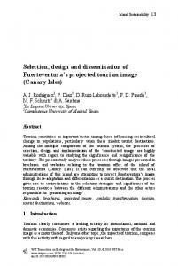
180 Fluid Structure Interaction VII implementation of the ICSP includes an experiment to investigate interesting phenomena and the independent simulation of experiment with computer codes. The development of prototypic research reactor fuel has been centered on two objectives; the continued reactor performance characteristics currently held by each facility while meeting all reactor specific safety requirements. To meet these objectives a monolithic uranium-molybdenum (U-Mo) alloy fuel design is being investigated, sketched in Figure 1(c) [1]. The currently deployed fuel is an aluminum clad fuel with uranium dispersed in aluminum matrix shown in Figure 1(b).
(a) Figure 1:
(b)
(c)
Cut cross section of fuel plates comprising (a) aluminum, (b) aluminum clad with uranium dispersed in aluminum matrix fuel meat, and (c) aluminum clad with a uranium molybdenum alloy foil fuel meat.
Significant progress has been made recently regarding the micro-structural performance of very-high density U-Mo alloy fuel. However, additional study of the macroscopic behaviour of these elements must be examined before the fuel can be fully implemented [2]. One critical area of study is the behaviour of reactor specific fuel elements under prototypic thermal hydraulic conditions [2, 3]. Several of U.S. High Performance Research Reactors (HPRRs) are licensed to operate at extreme heat fluxes, as a corollary their hydraulic designs require large flow rates sufficient to remove this heat. These flow rates may reach superficial velocities upwards of approximately 15 m/s through individual flow channels. Given that the fuel plates under discussion are relatively long (up to 1.257 m), wide (up to 0.140 m), and extremely thin (as small as 1.27 mm), concern is drawn toward the susceptibility of the onset of static and possibly dynamic plate mechanical response as a result of extreme hydraulic loading. Previous computational safety tools have utilized a conservative approach in determining a fuel plate’s mechanical response to a prescribed hydraulic load by assuming homogenous material properties of the most mechanically weak material within the fuel plate (e.g. aluminum) as seen in Figure 1(a). This is not representative of the physical plate configuration and ultimately forces the extrapolation of information outside of its applicable region. Continuing advancements in computational methods and tools enable more rigorous and sophisticated component design and safety analyses accessible to users that operate through personal desktop workstations, whereas traditionally these tools have been limited to only those that have access to supercomputers or clusters. The result is an expanding community of users that rely on advanced multi-physics software packages (e.g. computational tools that have the capability to produce results relating both fluid and solid domains, or fluidstructure interactions) to produce reliable and accurate results. Although the advancement of these software tools, in particular multi-physics packages, have made leaps in progress over the recent years, the effort to perform rigorous WIT Transactions on The Built Environment, Vol 129, © 2013 WIT Press www.witpress.com, ISSN 1743-3509 (on-line)
Fluid Structure Interaction VII
181
validation and verification of multi-physics packages has fallen short due to a lack of resources, problem complexities, and available experimental data. The objective of the experimental data which is yielded as a result of testing described herein is as follows: Identify the flow conditions which induce the onset of elastic plate deformation for an aluminum clad uranium-molybdenum fuel alloy; Identify the flow conditions which produce plate failure of each fuel plate material. The ICSP will provide hydro-mechanical experimental data to assess the interaction of fuel plates (solid domain) under a range of flow rates (fluid domain) while maintaining a stable boundary pressure and fluid temperature to verify the suitability for use of the prototypic uranium-molybdenum alloy based fuel. This experimental data may be utilized to assess multi-physics tools simulating the following phenomena: Flow disparity within a fuel plate assembly; Bulk computational thermal hydraulic characteristics; Influence of pressure boundary condition on solid domain; Fuel plate plastic deformation and vibration. The participants from IAEA Member States will be able to use safety analysis codes and/or general computational multi-physics codes to perform blind and open simulation of the experiment using initial and boundary conditions.
2 Test facility The experiment for this ICSP will take place in the thermal hydraulic test loop, HMFTF (Hydro-Mechanical Fuel Test Facility), located at Oregon State University (OSU). The current design of the HMFTF permits for hydraulic testing of a single full HPRR fuel element, and can cater to a broad range of operating conditions enveloping the U.S. HPRR lower operating limits to beyond design basis conditions as seen in Table 1. Because the HMFTF’s purpose is providing hydro-mechanical information, its design is currently limited to subcooled isothermal testing capabilities. Table 1:
HMFTF fluid operating range.
Parameter Flow Rate Range (liters/sec) Pressure Range (MPa) Fluid Temperature Range (°C) Conductivity Range (micromhos) pH Range
Value 0–100.94 0.101–4.137 20–238 1–3 4–8
The HMFTF test section is approximately 2.56 m (8.42 ft) in total length. Discrete locations along the length of the test section pipe are made available for the insertion of electrical wire leads for strain gages, pitot tubes for pressure
WIT Transactions on The Built Environment, Vol 129, © 2013 WIT Press www.witpress.com, ISSN 1743-3509 (on-line)
182 Fluid Structure Interaction VII transmitters, pressure indicating flow transmitters, and other hydraulic instrumentation as deemed necessary for a particular test. The test section is designed to provide a flexible interface for any desired test element which meats overall size criteria. This is achieved by designing individual test section element specific inserts which mate directly with the element. The purpose of these inserts is to simulate in-core flow conditions. These inserts are fed into the test section pipe and coupled to a universal interface to secure the insert and the element within the test section. A vaned flow straightener resides upstream of the test section providing for repeatable and well controlled inlet boundary conditions on the test section. The vaned flow straightener is located above the test section requiring that the flow direction be downward in the vertical direction through the test section. The ICSP described herein will take place in the downward flow direction, however, orientation is not anticipated to impact experimental or numerical results, as the test under discussion will take place in an isothermal environment, negating the influence of buoyancy forces within the test section region. The test element considered herein comprises six flat plates, and positioned near the outlet of the test section. A pitot tube assembly is hermetically sealed to the test section piping at the outlet of the test section. The assembly is aligned with the test section via locating press-fit dowel pins. The test section insert adjacent to the pitot tube assembly has a single slot cut out to allow the pitot tube plate to pass into the flow channel (Figure 2). The inserts are aligned in the test section such that a given element’s flow channels are approximately 0.0127 m (0.5 in) vertically below the pitot tubes. This allows each pitot tube to penetrate inside the element’s flow channels 0.0127 m (0.5 in) to acquire the true, local, dynamic pressure associated with that flow channel for a given fluid flow rate and temperature. The Test Plate Assembly (TPA) frame is designed for versatility, allowing the channel gaps (flow channels adjacent to each plate) to be varied so a range of channel gaps may be evaluated if necessary. The TPA design is modular, so the test plates may be assembled into the complete TPA prior to each test and disassembled at the conclusion of each test. By designing the TPA in such a modular manner, its frame may be used for all of the test plate sets, reducing the number of mechanical components requiring fabrication. Support combs are inserted between the plates at the inlet and the outlet of the channels. These combs limit the plate deflection at the inlet and outlet so that maximum deflection takes place in the middle of the plates (where the fuel region is located) instead of at the inlet and outlet; this allows for a qualitative comparison of the various fuel meat types and their relative resistance to hydraulic forces to be made. These combs are inserted into each channel at the center of the plate width. The TPA design consists of six plates separated by wire separators (Figure 3). The central two plates are referred to as the test plates while all other exterior plates are known as the hydraulic plates. During the ICSP test the hydraulic plates will comprise Aluminum 6061-T6 and the test plates will be Aluminum clad Depleted Uranium-Molybdenum monolithic foil. This design serves to
WIT Transactions on The Built Environment, Vol 129, © 2013 WIT Press www.witpress.com, ISSN 1743-3509 (on-line)
Fluid Structure Interaction VII
183
Test Section Pipe
Test Element
Figure 2:
HMFTF test section including test element.
Test Plate Spacer
Boundary Plate Hydraulic plates
Test Plates
Hydraulic plates Hydraulic plate spacer
Figure 3:
Boundary Plate
Component sketch of the TPA.
WIT Transactions on The Built Environment, Vol 129, © 2013 WIT Press www.witpress.com, ISSN 1743-3509 (on-line)
184 Fluid Structure Interaction VII allow for the appropriate hydraulic boundary conditions to be set through the incorporation of the hydraulic plates while all mechanical displacement is collected through the inner two test plates. All flow channel thicknesses are equally spaced to a nominal 0.075 inch height with the exception of the central channel which is adjustable in thickness to facilitate flow biasing and therefore inducing hydraulic loading on the central plates. The ICSP test will utilize a central channel thickness of 0.188 inches. The wire separators simulate pinned edge boundaries. All test plates are similar in nominal geometry (24 inches long, 4 inches wide, and 0.05 inches in thickness).
3 Experimental plan 3.1 Instrumentation plan Instrumentation includes test-section fluid pressure, flow rate, temperature, and plate deflection (through strain measurement), etc. The following in-facility instrumentation data shall be collected: Bulk fluid pH during the course of the experiment in the HMFTF; Bulk fluid conductivity during the course of the experiment in the HMFTF; Bulk fluid volumetric flow rate upstream of the test element; Bulk fluid temperature upstream of the test element; Bulk fluid temperature downstream of the test element; Bulk fluid pressure downstream of the test element; Local static fluid pressure in every flow channel near the outlet of the test element; Local total fluid pressure in every flow channel near the outlet of the test element; Local plate strain on two plates of interest in the test element; Local plate strain-temperature compensation on two plates of interests in the test element. All acquisition channels collect data at a rate of 2 Hz. Figure 4 presents a sketch of local measurement parameters relative to the general position of the TPA fuel plates. The purpose of adhering the strain gages to plates of interest (Test Plates) is to explicitly measure the deformation of the plates at discrete locations while the test is being performed lending to the acquisition of elasticplate deformation resulting from hydraulic forces and indication of the onset of plastic deformation. The location of the strain gages on the plates shall be similar (nominally) for both Test Plates located at approximately 6.125 inches from the leading (inlet) plate edge along the spanwise centerline. The strain gages are positioned on the plates at the estimated location of maximum plate deformation previously calculated during the design process of the TPA. The strain gages are configured in a Half Bridge Type I configuration to allow for temperature compensation such that flexural strain is explicitly acquired through the duration of the test.
WIT Transactions on The Built Environment, Vol 129, © 2013 WIT Press www.witpress.com, ISSN 1743-3509 (on-line)
Fluid Structure Interaction VII
185
2 x Bulk Flow Rate [gpm] 3 x Bulk Fluid Temperature [°F]
4 x Strain [%]
1 x Pressure Drop [psid]
7 x Static Pressure [psig] 7 x Total Pressure [psig]
1 x Static Pressure [psig] 3 x Bulk Fluid Temperature [°F]
Figure 4:
Sketch of measurement parameters.
The TPA comprises seven flow channels; in each flow channel both static and total pressure are measured near the outlet requiring a total of 14 local pressure measurements. These measurements are acquired through use of the pitot tube assembly including a total of 25 pressure transducers. The explicit location of all instrumentation including the sensing end of the pitot tubes is outlined in applicable as-built drawings to be included as a part of the test package and delivered during the first workshop. All data collected and presented in final format shall be maintained within an American Society of Mechanical Engineers (ASME) Nuclear Quality Assurance level 1 (NQA-1) quality assurance program. 3.2 Test procedure Plate failure during this study is defined as “Measurable plate deformation identified through use of the channel gap probe”; requiring the Test Plate’s yield WIT Transactions on The Built Environment, Vol 129, © 2013 WIT Press www.witpress.com, ISSN 1743-3509 (on-line)
186 Fluid Structure Interaction VII stress to be exceeded to meet this criteria. All current literature demonstrates that arrays of plates exposed to hydraulic loads undergo large plate deformation measurable during post testing (requiring plastic deformation) prior to observation of the plates’ dynamic response to these same hydraulic forces. In short, all literature demonstrates that plates statically undergo “plate failure” before responding in any dynamic fashion [4–9]. Hypothetically then, if each material set were to be tested under the same TPA geometric case number, the plates that are comprised of only aluminum 6061-O Temper would undergo plate failure when exposed to the lowest relative hydraulic forces, or as a corollary, when exposed to the lowest relative differential pressure across the TPA. The TPA shall be inserted into the HMFTF only after all required HMFTF system shakedown tests have been completed and a baseline configuration has been established. A set of flow tests shall then be performed on the baseline TPA. The ICSP tests shall maintain a flow rate of 95 gpm (driven by the minimum continuous operating flow rate of the HMFTF [10]) or lower while reaching equilibrium system pressure and fluid temperature in order to allow for fluid circulation through the loop, but prevent significant hydraulic loads on the baseline TPA. The test shall be performed at a consistent nominal system pressure of 450 psig. This pressure is driven by the maximum operating system pressure of the HMFTF [10]. Lastly the pH and conductivity should be held between 5.0 and 7.0, and less than 100 µS/cm, respectively. The method used to identify the flow rate which induces plastic plate deformation shall be a staggered increasing stair step of flow rate over the duration of the test until deformation is observed via strain gage readout. A graphical sketch of flow rate and plate strain versus time, shown in Figure 5, outlines an example of this overall process. An initial flow rate at the baseline 14
Flow Rate 12
Strain
SP-3
10
SP-2
8
SP-1
6
4
2
SP-0 0
≥ 5 minutes -2
0
5
10
15
20
25
30
35
40
45
Time
Figure 5:
Sketch of bulk flow rate and plate strain versus time in plate failure tests.
WIT Transactions on The Built Environment, Vol 129, © 2013 WIT Press www.witpress.com, ISSN 1743-3509 (on-line)
Fluid Structure Interaction VII
187
equilibrium state shall be reached (SP-0). Upon reaching initial conditions for a minimum of five minutes the flow rate shall be increased by two gpm (SP-1) and the plate’s strain shall be observed (this incremental step size of two gpm is driven by the total flow error of the pump head and its hysteresis). After a minimum of five minutes at SP-1 equilibrium, the flow rate shall be decreased back to SP-0 and the plate’s strain shall be observed. If the plate’s yield stress has not been reached the plate’s deformation should remain in the elastic state and therefore return to its original strain readout at initial SP-0 state. After a minimum of five minutes at SP-0 equilibrium flow rate the flow shall then be increased by an additional two gpm from SP-1. This process shall continue until the observation of the plate’s strain is as shown when decreasing from SP-3 down to SP-0. In Figure 5, notice that although the flow rate decreased to the baseline equilibrium state, the strain does not. This provides evidence that plastic deformation took place and was induced by hydraulic loads imposed between flow rates of SP-2 and SP-3.
4 Validation of computer codes 4.1 Blind calculation Initial and boundary conditions such as system pressure, fluid temperature, test element geometry, and solid body material properties obtained from the experiment will be given to ICSP participants for blind calculation. This experimental data may be utilized to assess multi-physics tools simulating the following phenomena: Flow disparity within a fuel plate assembly; Bulk computational thermal hydraulic characteristics; Influence of pressure boundary condition on solid domain; and Fuel plate plastic deformation and vibration. The participants from IAEA Member States will be able to use safety analysis codes and/or general computational multi-physics codes to perform a blind simulation using test initial/boundary conditions. The calculated result will be provided by all participants to Oregon State University in an Excel spreadsheet. An Excel template will be provided to the participants. The calculated plate displacement should closely associate with the location of the strain gages adhered to the Test Plates. The expected fluid domain output is (1) flow rate and pressure for inlet and outlet, (2) pressure, flow rate and velocity for each channel. The expected solid domain output is deflection and stress for each test plate. 4.2 Open calculation Table 2 shows the proposed schedule for the ICSP implementation. Full experimental data in addition to initial and boundary conditions will be open to all ICSP participants after the collection of blind calculation results. During the phase of open calculation, participants can try to improve the analysis model, including sensitivity study, to produce a better result which is closer to the
WIT Transactions on The Built Environment, Vol 129, © 2013 WIT Press www.witpress.com, ISSN 1743-3509 (on-line)
188 Fluid Structure Interaction VII experimental data. Participants could identify any weakness or advantages of their prediction tools, search a way to overcome any limitations, and also suggest any further experiments or analytical models to fill the gap identified in the ICSP. Table 2: Proposed schedule for the ICSP. 2013 1Q
Select participants Conduct experiments (OSU) 1st workshop Distribute initial and boundary conditions Perform blind calculation 2nd workshop Perform open calculation 3rd workshop Documentation Last workshop
2Q
3Q
2014 4Q
1Q
2Q
3Q
2015 4Q
1Q
2Q
3Q
4Q
√
√
√ √
5 Conclusions IAEA organizes an ICSP on “Prediction of Hydro-Mechanical Behavior in Reactor Core with a Plate-type Fuel Assembly” and invites the participation of interesting institutes from IAEA Member States. The ICSP will conduct an experiment to identify the flow conditions which induce the onset of elastic plate deformation for fuel plate and to identify the flow conditions which produce plate failure of each fuel plate material. This experimental data may be utilized to assess multi-physics tools simulating the following phenomena: flow disparity within a fuel plate assembly, bulk computational thermal hydraulic characteristics, influence of pressure boundary condition on solid domain, and fuel plate plastic deformation and vibration. The participants from IAEA Member States will be able to use safety analysis codes and/or general computational multi-physics codes. Through the ICSP, participants could identify any weakness or advantages of their prediction tools, search a way to overcome any limitations, and also suggest any further experiments or analytical models to fill the gap identified in the ICSP. Detailed information on the ICSP is available from the IAEA website [11].
References [1] Wachs, D.M., Clark C.R., and Dunavant R.J., Conceptual Process Description for the Manufacture of Low-Enriched Uranium-Molybdenum Fuel, Idaho National Laboratory, Idaho Falls, pp. 1-29, 2008. WIT Transactions on The Built Environment, Vol 129, © 2013 WIT Press www.witpress.com, ISSN 1743-3509 (on-line)
Fluid Structure Interaction VII
189
[2] Marcum, W.R., Woods B.G., and Wachs D.M., High Performance Research Reactor Fuel Development Hydraulic Test Loop, Oregon State University, Corvallis, USA, 2008. [3] Wachs, D.M., RERTR Fuel Development and Qualification Plan, Idaho National Laboratory, Idaho Falls, USA, 2007. [4] Groninger, R.D. and Kane J.J., Flow Induced Deflections of Parallel Flat Plates. Nuclear Science and Engineering, 16, pp. 218-226, 1963. [5] Davis, D.C. and Kim G., Design Against Hydrodynamic Instabilities in Flat-Plate Type Fuel Element Assemblies, International Conference on Structural Mechanics in Reactor Technology, Tokyo Japan, 1991. [6] Kim, G. and Davis D.C., Hydrodynamic Instabilities in Flat-Plate-Type Fuel Assemblies, Nuclear Engineering and Design, 158, pp. 17, 1995. [7] Smissaert, G.E., Static and Dynamic Hydroelastic Instabilities in MTRType Fuel Elements Part I. Introduction and Experimental Investigation, Nuclear Science and Engineering, 7, pp. 11, 1968. [8] Smissaert, G.E., Static and Dynamic Hydroelastic Instabilities in MTRType Fuel Elements Part II. Theoretical Investigation and Discussion. Nuclear Science and Engineering, 9, pp. 17, 1969. [9] Stromquist, W.K. and Sisman O., High Flux Reactor Fuel Assemblies Vibration and Water Flow., Oak Ridge National Laboratory, USA, 1948. [10] Marcum, W.R., OSU HMFTF Facility Description Report, OSU-HMFTF000000-TECH-003, Oregon State University, Corvallis, USA, 2011. [11] IAEA International Collaborative Standard Problem on Prediction of Hydro-Mechanical Behavior in Reactor Core with a Plate-type Fuel Assembly, http://www.iaea.org/NuclearPower/WCR/ICSP-plate-fuel.html
WIT Transactions on The Built Environment, Vol 129, © 2013 WIT Press www.witpress.com, ISSN 1743-3509 (on-line)