Predictive control implementation in a PLC using the IEC 1131.3 programming standard G. Valencia-Palomo, K. Hilton and J.A. Rossiter
Abstract— In this paper an implementation of a Generalized Predictive Controller (GPC) is presented. The controller was programmed in an industrial Programable Logic Controller (PLC) software using the IEC 1131.3 programming standard. The algorithm was kept as simple as possible to overcome capability problems of the hardware. Experimental tests were carried out to control a first and second order bench-scale systems. The results of this work encourage to keep working in developing simple predictive algorithms to be programmed in industrial standard hardware. Keywords: Predictive control, GPC, PLC, IEC-1131.3.
I. I NTRODUCTION Lineal model predictive control (MPC) is now well studied and understood [1], [4], [8]. The advantages of predictive control, such as the ease extension to the multivariable case and the enhanced constraint handling, makes this control strategy attractive to the academic community. Here, the research is now mainly focused in nonlinear predictive control as evidenced by specialized conferences in this specific area. But in the industry, despite some successful applications, predictive control still being regarded as an academic concept rather than a commercial control scheme, especially for SISO control loops where PI controllers are the only option. The issues for more widespread utilization can be putted together in tree main groups [6]: 1) Controller set up. This involves the design, tuning and maintenance of the controller. This tasks should be as simple as possible so the technicians can do the job without the need of experts. 2) The hardware. The control algorithm should be in standard hardware of industry such as existing PLCs to not fall into more expenses. 3) Promotion and support. Training the technical staff to relate the tuning parameters in order to be confident users of the controllers. These three factors has been the key for the success of the Predictive Functional Control (PFC) [5] which perhaps is the predictive control algorithm with more industrial applications. Ironically, despite is obvious success, the academic community has shied away from PFC because its mathematical foundations are not as systematic or rigorous as other approaches. All authors are with the Department of Automatic Control and Systems Engineering, Mappin Street, University of Sheffield, South Yorkshire, UK. S1 3JD.
[email protected],
[email protected].
Having this in mind, this paper seeks and encourage the academic community to put more effort in designing and promoting simple control algorithms that can be set up in standard PLC units. The idea is to develop MPC controllers that becomes an alternative for SISO control loops that are difficult to regulate with conventional PI controllers. The aim of this paper is to develop a GPC controller programmed in a PLC using the IEC 1131.3 programming standard. One of the concerns is to investigate the hardware capabilities since a demanding feature of most model predictive controllers is that an optimization must be solved online. This paper is organized as follows: in the second section will be briefly introduced the GPC, in the third section the industrial PLC is presented, the fourth section contains information about the structure of the program in the PLC, in the fifth section the experimental results are shown. The paper finishes with conclusions and plans for future work. II. P REDICTIVE CONTROL In this section is introduced standard material from the existing literature on MPC that is going to be used for the control implementation. The algorithm will be kept as simple as possible for the ease of the implementation. Consider the discrete-time system with no disturbing and no measurement errors: ( x (k + 1) = Ax (k) + Bu (k) (1) y (k) = Cx (k) where x(k), y(k) and u(k) are the state vector, the measured output and the process input respectively. x(k) ∈ Rn , in the SISO case: y(k), u(k) ∈ R. A MIMO process has the same description but with y(k) ∈ Rl and u(k) ∈ Rm . By simplicity in the notation only the first case is considered, the extension to MIMO case is straightforward. By iterating the model, the output prediction with a prediction horizon HP and a control horizon HC is given by: ˆ HP = FHP + GHP C ∆UHC Y (2) ˆ HP , ∆UHC , FHP and GHP C are defined where matrices Y as follows: £ ¤ ˆ HP = ˆy (k + 1|k) . . . ˆy (k + HP |k) T Y £ ¤T ∆UHC = ∆ u (k|k) . . . ∆u (k + HC |k)
FHP
GH P C
CA .. .
CB .. .
T
PHC −1 i H C CA CA B x (k) + Pi=0 = u (k − 1) H H +1 i C CA C CA B i=0 . . .. .. PHP −1 i CAHP CA B i=0 CB ··· 0 .. .. .. . . . PHC −1 .. i . CA B CB = Pi=0 HC i ··· CAB + CB i=0 CA B .. .. .. . . . PHP −1 PHP −HC i i CA B · · · CA B i=0 i=0
The set of control increments is calculated by minimizing an objective function for a prediction horizon. The objective is to minimize the error between the predicted output ˆy(k) and the reference trajectory w(k) along the prediction horizon: J=
HP X
2
kˆy (k + j|k) − w (k + j|k)k +
j=1
HC X
2
(3) where the second term in the Eq. (3) is the control effort and λ is the weighting sequence factor. The reference trajectory w(k), is the desired output in closed loop of the system and is given by: w (k + i|k) = s (k + i) − αi [s (k) − y (k)] ; 1 ≤ i ≤ HP (4) where s(k) is the set-point and α determines the smoothness of the approach from the output to s(k). For the disturbance rejection, all that is necessary is to measure the discrepancy between the prediction and the latest plant output and then subtract that discrepancy from the reference trajectory at the coincidence points: d(k) = y(k) − ˆy(k|k − 1)
(5)
The considered constraints are: limits in the control signal (Umin ,Umax ) and limits in the slew rate of the actuator (∆umin ,∆umax ). But for this implementation they are not going to be taken in account in the optimization procedure, since the systems to be controlling are well known and the behavior they present matches with the ones that are noticed in [7], where is argued that for this special cases saturation is the optimal solution. If £ ¤ W = w (k + 1|k), . . . , w (k + HP |k) , then, the objective function (3) can be expressed in terms of the predicted output (2): min J (∆UHC ) =
1 ∆UTHC H∆UHC + fT ∆UHC + b (6) 2
³ ´−1 ∆UOpt = GTHP c GHP c + λI GHP c (W − FHP + 1d) (7) From the set of control increments, only the first one is applied to the plant and for the next sampling instant the sequence is repeated. III. P ROGRAMABLE L OGIC C ONTROLLER (PLC) AND THE IEC 1131.3 PROGRAMMING STANDARD
k∆u (k + j|k)kλ
j=1
where: ³ b = (FHP − W −´1d) (FHP − W − 1d) , H = GTHP C GHP C + λI , fT = 2(FHP − W − 1d)T GHP C and 1 is an unitary vector with suitable dimensions. Therefore the solution takes the form of a standard unconstrained Quadratic Programming (QP) formulation. The objective function (6) is convex since it is quadratic with positive definite Hessian (H > 0) [2]. The optimal solution can be written as:
In this section is presented an overview of the hardware that will be used for the control application. A. Why a PLC? PLCs are by far the most accepted computers in industry which offer a reliable and robust system, are relatively simple to program and debug, includes dedicated I/O, communication, memory expansion etc. The arrangement and packaging of the PLC system is tailored for ease of integration into on-site control racks or cabinets with minimal effort. They are also suited for the ease of implementation of standard wiring terminations. Each of these means that any on-site technician will have no difficulty or require any additional skills or tools when it comes to installing a controller. PLC systems offer an added advantage that the program can be monitored online. The visual nature of the language means that the user can view in real-time the changing nature of bits, the value of counters or timers etc and how these relate to the overall program structure. Another advantage which PLC systems afford is that in the most case, adjustments to programs can be made online without having to take the process or system under control offline. This is obviously an attractive property to industry as shutting down parts of a process can be a very costly affair indeed. However, it must be noted that obviously, this does present some safety issues which must be carefully addressed beforehand. B. Allen Bradley – Rockwell Automation Inc. PLC system This development is focused in the family of the SLC500 processors belonging to the Allen Bradley PLC systems, one of them could be seen in Fig. 1. A commercial publication by Rockwell Automation Inc. [3] has the information shown in Table I about this PLCs.
0001 DEBOUNCE_OFF SWITCH_IN (/)
SWITCH_OUT (R)
T_ON IN
DEBOUNCE_TIME
Q
PT
ET
002
0002 DEBOUNCE_OFF SWITCH_IN (/)
SWITCH_OUT (R)
T_ON
DEBOUNCE_TIME
IN
Q
PT
ET
002
Fig. 2. Fig. 1.
Allen Bradley PLC – SCL500 processor family.
DEBOUNCE_ON SWITCH_IN
TABLE I SLC500 PROCESSORS SPECIFICATIONS . Mem. size (words) Max. I/O Max. rack slots Bit execution Real time clock
SLC501 1k/4k 3940 3/30 4µs No
SLC502 4k 4096 3/30 2.4µs No
SLC503 8k/16k 4096 3/30 0.44µs Yes
Ladder diagram language. T_ON
IN
Q
PT
ET
SWITCH_STATE 001
SLC504 16k/32k 4096 3/30 0.37µs Yes
SR S1
Q1
SWITCH_OUT
R
003
DEBOUNCE_OFF T_ON
DEBOUNCE_TIME
IN
Q
PT
ET
002
Fig. 3.
Function block diagram language.
C. The IEC 1131.3 programming standard The Allen Bradley set of PLC includes the facilities to be programmed in 3 of the 5 languages in agreement with the 1131.3 standard using Control Logix 500T M software programming package. Each of these allows for any combination of programming languages to be used for a single project. These languages are: 1) Ladder Diagram is a graphical language that uses a standard set of symbols to represent relay logic. The basic elements are coils and contacts which are connected by links. Links are different from the wires used in Function Block Diagram because they transfer only binary data between Ladder Diagram symbols, which follow the power flow characteristics of relay logic. Function blocks and function elements must have at least one binary input and output in Ladder Diagram. Ladder logic is thus a highly visual, easy to understand, program and diagnose as previously stated. An example of this language is illustrated in Fig 2. 2) Function Block Diagram is a graphical language that corresponds to circuit diagrams. The elements used in this language appear as blocks wired together to form circuits. The wires can communicate binary and other types of data between Function Block Diagram elements (e.g. Real, Integers, Double Integers). In Function Block Diagram, a group of elements visibly interconnected by wires is known as a network. An Function Block Diagram can contain one or more networks. An example of this language is illustrated in Fig. 3. 3) Structured Text is a general purpose, high-level programming language, similar to PASCAL or C. Struc-
tured Text is particularly useful for complex arithmetic calculations, and can be used to implement complicated procedures that are not easily expressed in graphical Languages such as Function Block Diagram or Ladder Diagram. Structured Text allows you to create boolean and arithmetic expressions as well a structured programming constructs such as conditional statements (IF, THEN, ELSE). Functions and function blocks can be invoked in this language. D. Programming issues The SCL500 ControlLogix Controllers together with RSLogix 500T M allows for the memory allocation of matrices (which it refers to as data arrays), for up to 3 dimensions. However, with the exception of one-dimensional, simple element by element arithmetic, they do not lend themselves easily to other matrix operations, notably: transposition, inversion and multiplication. To achieve such functions, it is thus necessary to design the software to perform such operations from scratch. Also, all the algorithm could be written in Structured Text, but for the better understanding of technicians is strongly advisable to program most of the algorithm in a graphical language. In this way, they could view all the real-time data of the controller and debug the program if need it, in a more intuitive way. Finally, all the computations to calculate the next control movement should be done in a limited time dictated by the sampling period, so the computational load should be kept as low as possible to avoid accumulated errors during the tests. Moreover, a bigger program requires more memory, therefore a more powerful PLC with the associated cost.
IV. P REDICTIVE CONTROL IN THE PLC The complete structure of the program is shown in Fig. 4. The predictive control in this work is programmed in the High Priority Periodic Execution Group1 called GPC Controller witch contains the following routines: ¦ GPC MAIN (Function Block Diagram). Is the main routine, its purpose is to control the programs execution, calling routines as and when they are needed. Contains all the previous needed declarations such as: model of the plant, controller parameters, etc. Here is also calculated the disturbance with eq. (5). ¦ Exp Trajectory Reference (Function Block Diagram) Called from a FOR loop in GPC MAIN (J = 1 to HP ). Program calculates the current error between the current plant output and the desired set point, also generates the future trajectory of reference using the eq. (4). ¦ Output Predictions (Function Block Diagram) Called from a FOR loop in GPC MAIN (J = 1 to HP ). Program contains the controllers’ estimation of the plant model which is required to be hardcoded by the user. ∗ First scan. Disables the reading of the plant output, then performs the necessary operations to precompute the matrix GHP C . ∗ Next scans. Reads in current value of plant output. Forms predictions of the plant output for the next HP cycles using eq. (2). ¦ G Matrix Formation (Structured Text) Called from a ‘Jump to Subroutine’ command from GPC MAIN. Only enabled on the FIRST SCAN. Precomputes the matrix GHP C since this matrix just depend in the model of the plant. After this has been executed, it sets the a Bit to ‘Done’, this disables this routine from proceeding scans as well as a further test happening in program Output Predictions. ¦ Controller Output (Function Block Diagram) Called from a ‘Jump to Subroutine’ command in GPC MAIN. This routine calculates FHP − W − 1d, then calls the U DELAT LEAST SQUARES routine via a ‘Jump to Subroutine’ command. After this routine returns a value for ∆U, the new control signal U(k) = U(k − 1) + ∆U(k) is sent to the plant. ¦ U Delta Least Squares (Structured Text) Accessed from the Controller Output routine via a ‘Jump to Subroutine’ instruction. Most complex routine which must pass parameters into three other routines for matrix multiplication, transposing and inverse. This is used to calculate the set of control increments using eq. (7). ¦ Matrix Multiply (Structured Text) Called a number of times from the U Delta Least Squares routine via a ‘Jump to Subroutine’ command. The matrix dimensions are passed to this along with two matrices. 1 This
periodicity is set up with the chosen sample time.
Fig. 4.
Fig. 5.
Structure of the predictive algorithm in the target PLC.
Predictive control algorithm memory usage on the target PLC.
The routine returns the resulting answer matrix of the multiplication. ¦ Matrix Inverse (Structured Text) Called from the U Delta Least Squares routine via a ‘Jump to Subroutine’ command. The matrix dimensions are passed to this along with one matrix. The routine returns the resulting inverted matrix using augmented matrix with gaussian elimination. ¦ Matrix Transpose (Structured Text) Called from the U Delta Least Squares routine via a ‘Jump to Subroutine’ command. The matrix dimensions are passed to this along with one matrix. The routine returns the resulting transposed matrix. ¦ PLANT SIMULATION (Function Block Diagram) FOR DEVELOPMENT PURPOSES ONLY Called from GPC MAIN routine via a ‘Jump to Subroutine’ command. Used to simulate the plant dynamics/response and to test the controller offline.
Sensor
Heating grid
Parameter Sampling time Prediction horizon (HP ) Control horizon (HC ) Trajectory of ref. constant (α) Weighting factor (λ)
Air blower
Fig. 6.
TABLE II C ONTROLLER TUNING PARAMETERS FOR THE EXPERIMENTAL TESTS .
Heating process.
Heating proc. 10 sec 10 3 0.9 0.6
Speed proc. 0.1 sec 10 3 0.7 5
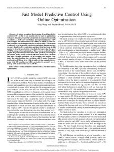
Heating process 36 34
Output ( oC )
32 30 28 26 24 Experimental data Mathematical model
22 20
48
50
Fig. 7.
52
54
56 58 60 Time (min)
62
64
66
Model validation of the heating process.
Fig. 8.
Online monitoring for the heating process. Heating process
32
26 24 22 20 18
This section shows the experimental results from regulate a first and a second order plant with the controller.
x (k + 1) = 0.94x (k) + u (k)
5
10
15
0
5
10
15
20
25
30
35
40
25
30
35
40
Input (V)
3 2 1 0
Fig. 9.
20 Time (min)
Experimental test for the heating process. Heating process
40 35 30 25
Setpoint Output
20
y (k) = 0.94x (k)
0
10
20
0
10
20
30
40
50
40
50
4 Input (V)
The experimental validation of the mathematical model is shown in Fig. 7. The tuning is done by taken largest prediction horizon HP and control horizon HC . For the proposed program this is HP = 10 and HC = 3. The rest of the tuning parameters are shown in Table II. The screen shot in Fig. 8 shows the online monitoring of the process and can be seen that the plant output is successfully tracking the reference signal. For a better display of the results, the data is plotted separately in Figs 9 and 10.
0
4
Output ( oC )
The first experiment attempt to control a heating process consisting in a centrifugal blower, a heating grid, a tube and a temperature sensor. See Fig. 6. The objective is to control the temperature at the end of the tube manipulating the speed of the blower. The model of the plant is done by non-parametrical identification and discretizing the model to obtain the model for prediction. The resulting discrete model with a sampling time of 10s is:
Output
28
V. E XPERIMENTAL TESTS
A. First order plant – Temperature control
Setpoint
30 Output ( oC )
It can be seen from the properties of the controller with the RSLogix programming tool (Fig. 5) that the program uses 15% of the available storage of the PLC including required memory for I/O, running cache and other necessary subroutines.
3 2 1 0
Fig. 10.
30 Time (min)
Experimental test for the heating process.
Speed process 1000 980 960
Output (RPM)
940 920 900 880 860 840 820
Experimental data Mathematical model
800 35
40
45
50
55
60
Time (sec)
Fig. 11.
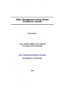
Model validation of the speed process. Speed process
Fig. 13.
1000
Execution time of the controller for the speed process.
Output ( RPM )
Setpoint Output
950 900
VI. C ONCLUSIONS
850 800
0
0.5
1
1.5
2
0
0.5
1 Time (min)
1.5
2
4.3
Input (V)
4.25 4.2 4.15 4.1 4.05
Fig. 12.
Experimental test for the speed process.
This paper presents an implementation of a GPC controller in a PLC with the objective of embedding a predictive control algorithm in standard industrial hardware. The authors believe that there is a potential here to propose more rigorous algorithms that could be equally embedded in standard hardware, keeping it simple, realistic to make MPC become a real option to replace the conventional controllers in SISO loops that are normally hard to regulate with these. The achieved results encourage the future plans to include the constraint handling and simple auto-tuning rules to the controller as proposed in [9]. VII. ACKNOWLEDGMENTS
B. A second order plant – Speed control This process consist in a motor fitted with a speed sensor, the control objective is to regulate the speed of the motor by manipulation of the input voltage. The same procedure as in the fist experiment is applied. The mathematical model of the system with a sampling time of 0.1 sec is: · ¸ · ¸ 0.93 −0.01 1 x (k + 1) = x (k) + u(k) 0.04752 0.9964 0 £ ¤ y (k) = −0.01 3.71 x(k) The experimental validation is shown in Fig. 11 and the tuning parameters are in Table II. Once again, the results in Fig. 12 shows a that the MPC is tracking the set point accurately. It should be noticed that in this case the time to calculate the input signal could become critical since the sample time is much faster than the first experiment. The diagnostics tool from the hardware (shown in Fig. 13) displays that the time for scaning the program each sample time oscillates between 9.33 ms and 11.64 ms while the elapsed time between triggers (sampling instants) oscillates between 99.32 ms and 100.76 ms.
The authors would like to thank to Jaques Richalet for his advices and suggestions in this project. R EFERENCES [1] E. Camacho and C. Bordons. Model predictive control. Springer Verlag, 2nd edition, 2004. [2] R. Fletcher. Practical methods of optimization. John Wiley, 2nd edition, 1987. [3] Rockwell Automation Inc. Allen Bradley’s SLC 500TM Processors: Small Controllers for Big Applications. Publication 1747-1.6, USA, 1997. [4] J.M. Maciejowski. Predictive control with constraints. Prentice Hall, 2002. [5] J. Richalet. Practique de la commande predictive. Hermes, France, 1993. [6] J. Richalet. Industrial application of predictive functional control. In Nonlinear Model Predictive Control, Software and Applications, Loughborough, UK, 2007. [7] O.J. Rojas and G.C. Goodwin. A simple antiwindup strategy for state constrained linear control. In IFAC World Congress, Barcelona, Spain, 2002. [8] J.A. Rossiter. Model predictive control: a practical aproach. CRC Press, 2003. [9] G. Valencia-Palomo and J.A. Rossiter. The potencial of auto-tuned MPC based on minimal plant information. In Assessment and Future Directions of Nonlinear Model Predictive Control, Pavia, Italy, 2008.