Predictive Control of Two Parallel Induction Machines fed by a Six-Leg Indirect Matrix Converter under an Unbalanced AC-Supply M. L´opez∗ , M. Rivera† , C. Garc´ıa∗ , J. Rodriguez∗ , R. Pe˜na‡ , J. Espinoza‡ , and P. Wheeler§
∗ Department
of Electronics Engineering, Universidad T´ecnica Federico Santa Mar´ıa, Valpara´ıso, CHILE, Email:
[email protected] † Department of Industrial Technologies, Universidad de Talca, Curic´ o, CHILE, Email:
[email protected] ‡ Department of Electrical Engineering, Universidad de Concepci´ on, Concepci´on, CHILE Email:
[email protected],
[email protected] § Department of Electrical and Electronics Engineering, Nottingham University, Nottingham, U.K. Email:
[email protected]
Abstract—This paper proposes a predictive torque and flux control for a multi-motor drive system. The scheme is based on a six-leg indirect matrix converter used to drive two induction machines operating at the same speed even under different load torque conditions. By using the mathematical model of the converter and machines, the proposed control scheme selects the switching state that minimizes error in the torque, flux and reactive power predictions, according to their reference values. Through simulation results it is shown that the predictive approach can be simply implemented with a good tracking of the controlled variables to their respective references. The results verify the fast dynamic response of the torque in both machines and demonstrate effective compensation of reactive power in transient and steady state under an unbalanced ac-supply.
vs is vi ii 𝑣𝑑𝑐 𝑖𝑑𝑐 vx ix 𝑅𝑑 𝐿𝑓 𝐶𝑓 𝑅𝑠 𝑅𝑟 𝜙𝑠 𝜙𝑟 𝐿𝑠 𝐿𝑟 𝐿𝑚 ir 𝜔𝑟𝑥 𝑝 𝐽 𝑇𝑐
N OMENCLATURE Source voltage Source current Input voltage Input current DC-voltage DC-current Load voltage motor 𝑥 = 1, 2 Load current motor 𝑥 = 1, 2 Damping filter resistor Input filter inductor Input filter capacitor Stator resistor Rotor resistor Stator flux Rotor flux Stator inductance Rotor inductance Leakage inductance Rotor current Electric rotor speed IM ’x’ Poles pair Inertia momentum Load torque
[𝑣𝑠𝐴 𝑣𝑠𝐵 𝑣𝑠𝐶 ]𝑇 [𝑖𝑠𝐴 𝑖𝑠𝐵 𝑖𝑠𝐶 ]𝑇 [𝑣𝐴 𝑣𝐵 𝑣𝐶 ]𝑇 [𝑖𝐴 𝑖𝐵 𝑖𝐶 ]𝑇 [𝑣𝑎𝑥 𝑣𝑏𝑥 𝑣𝑐𝑥 ]𝑇 [𝑖𝑎𝑥 𝑖𝑏𝑥 𝑖𝑐𝑥 ]𝑇
[𝜓𝑠𝑎 𝜓𝑠𝑏 𝜓𝑠𝑐 ]𝑇 [𝜓𝑟𝑎 𝜓𝑟𝑏 𝜓𝑟𝑐 ]𝑇
[𝑖𝑟𝐴 𝑖𝑟𝐵 𝑖𝑟𝐶 ]𝑇
I. I NTRODUCTION Applications for multi-drive systems are varied, for example conveyor belts or product assembly lines for manufacturing processes, as described in [1]. Usually multi-drive systems are controlled by a rectifier feeding a common dc-link, to which a series of inverters are then coupled to control other machines or power other equipment. In [2] and [3], the authors propose topologies and control strategies based on two-level voltage source inverters to control several three or five-phase permanent magnet synchronous machines. The aim of this proposal is to reduce the number of legs required to power the machines and therefore to optimize cost, weight and size. In [4], the authors develop a study of multi-drive systems, suggesting several possible configurations. In particular, and from an electrical standpoint, they address matrix converters controlled by vector modulation in order to maintain the same speed. From a physical standpoint, they seek to characterize advantages of the converter’s size and weight. Due to technological advances and the emergence of faster microcontrollers that are capable of more powerful calculations, predictive control techniques have emerged as a new alternative for power converter applications [5]. This technique is a very intuitive concept that is easy to implement in diverse systems. It performs well considering numerous restrictions, such as compensation for downtime or nonlinearities in the system, it offers a flexible control technique, and it is easily extendible for different applications, as described in [5]–[11]. In this paper, a predictive torque and flux control method is proposed for two induction machines fed by an indirect matrix converter of six legs operating under AC voltage imbalances. The model naturally includes the AC input voltage unbalance and thus can minimize its effects. The algorithm minimizes a cost function, that implicitly assures instantaneous reactive power minimization, and flux and torque equal to a given reference. Through simulation results, the feasibility of the proposed strategy will be demonstrated, and some
𝑖𝑑𝑐 vs
𝑅𝑓 𝑖𝑠𝐴
𝑁
𝑅𝑑 𝐿𝑓
𝑆𝑟1 vi 𝐴
𝑖𝑠𝐶
𝑆𝑟5
𝑆𝑖11
𝑖𝑖𝐴 𝐵
𝑖𝑠𝐵
𝑆𝑟3
𝐶𝑓
𝑆𝑖15
𝑎1
𝑖𝑖𝐵 𝑖𝑖𝐶 𝐶 𝑆𝑟4
𝑆𝑖13
𝑏1 𝑐1 𝑆𝑟6
𝑆𝑟2
𝑆𝑖14
𝑆𝑖16
𝑆𝑖12
𝑆𝑖21
𝑆𝑖23
𝑆𝑖25
𝑎2 𝑣𝑑𝑐 > 0
𝑏2 𝑐2
𝑆𝑖24 Fig. 1.
𝑆𝑖26
𝑖𝑎1
Induction Machine 1 v1
𝑖𝑏1
IM
𝑖𝑐1
𝑖𝑎2
Induction Machine 2 v2
𝑖𝑏2
IM
𝑖𝑐2
𝑆𝑖22
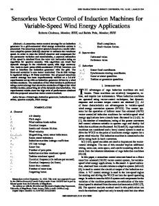
Multi-drive system fed by a six-leg indirect matrix converter.
implementation issues will be addressed. II. T OPOLOGY AND M ATHEMATICAL M ODEL OF THE M ULTI -D RIVE S YSTEM Figure 1 shows the topology implemented in the proposed multi-drive system. The converter is composed of a current source rectifier (CSR) and two voltage source inverters (VSI), which are connected to the rectifier through a dc-link without energy storage elements. The rectifier and inverter of this structure have six and eight valid switching states, respectively. One of the restrictions of operating the indirect matrix converter is that there must always be a positive voltage in the dc-link, in addition to never short-circuiting the ac input sources or opening an output leg. Thus, only three states of the rectifier are valid at every moment; thus, the total number of valid states of the converter is 3𝑥8𝑥8=192. The mathematical model of the six-leg indirect matrix converter is obtained from [12]. The dc-link voltage 𝑣𝑑𝑐 is obtained as a function of the rectifier switches and the input voltage vi , as follows: ] [ 𝑣𝑑𝑐 = 𝑆𝑟1 − 𝑆𝑟4 𝑆𝑟3 − 𝑆𝑟6 𝑆𝑟5 − 𝑆𝑟2 vi . (1) The input currents ii are defined as a function of the rectifier switches and the dc-link current 𝑖𝑑𝑐 , as in the following: ⎤ ⎡ 𝑆𝑟1 − 𝑆𝑟4 ii = ⎣ 𝑆𝑟3 − 𝑆𝑟6 ⎦ 𝑖𝑑𝑐 . (2) 𝑆𝑟5 − 𝑆𝑟2
The dc-link current 𝑖𝑑𝑐 is determined as a function of the inverter switches and the output currents i1 and i2 : ] [ 𝑖𝑑𝑐1 = [ 𝑆𝑖11 𝑆𝑖13 𝑆𝑖15 ] i1 , 𝑖𝑑𝑐2 = 𝑆𝑖21 𝑆𝑖23 𝑆𝑖25 i2 , (3) 𝑖𝑑𝑐 = 𝑖𝑑𝑐1 + 𝑖𝑑𝑐2 . The output voltage is synthesized as a function of the inverter switches and the dc-link voltage 𝑣𝑑𝑐 , as shown in equation (4). ⎡ ⎤ 𝑆𝑖11 − 𝑆𝑖14 ⎢ ⎥ ] ⎢ 𝑆𝑖13 − 𝑆𝑖16 ⎥ [ ⎢ 𝑆𝑖15 − 𝑆𝑖12 ⎥ v1 ⎥ =⎢ (4) vo = ⎢ 𝑆𝑖21 − 𝑆𝑖24 ⎥ 𝑣𝑑𝑐 . v2 ⎢ ⎥ ⎣ 𝑆𝑖23 − 𝑆𝑖26 ⎦ 𝑆𝑖25 − 𝑆𝑖22 The rectifier includes an 𝐿𝐶 filter at the input, which is necessary to prevent overvoltages caused by the high frequency switching of the input stream produced by the switching and inductive nature of the load. The mathematical model of the 𝑅 𝑠 𝐿𝑠 − 𝐿𝑚 vo
io
𝑅𝑟
𝐿𝑟 − 𝐿𝑚 𝐿𝑚
𝜓s
+ 𝑗𝜔𝑟 𝜓r
𝜓r + vr
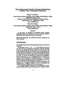
Fig. 2.
Equivalent circuit model of the induction machine.
input filter, using the Clarke transform can be obtained in the stationary axis 𝛼𝛽, as presented in equations (5) and (6). ) ( 𝐿𝑓 𝑅 𝑑 𝑠 𝛼𝛽 𝛼𝛽 + 𝑅𝑓 i𝛼𝛽 (5) s = vs − vi , 𝐿𝑓 𝑠 + 𝑅 𝑑 𝑑vi𝛼𝛽 1 𝛼𝛽 = (i − i𝛼𝛽 (6) i ). 𝑑𝑡 𝐶𝑓 s A simplified model of the system which does not consider the damping resistor is defined as follows: 1 𝑅𝑓 𝛼𝛽 1 𝛼𝛽 𝑑 𝛼𝛽 i = − vi𝛼𝛽 − i + v , 𝑑𝑡 s 𝐿𝑓 𝐿𝑓 s 𝐿𝑓 s
(7)
𝑑vi𝛼𝛽 1 𝛼𝛽 = (i − i𝛼𝛽 (8) i ). 𝑑𝑡 𝐶𝑓 s The flux generated in the stator and rotor are obtained according to the currents in each winding and their respective inductances, as follows: 𝜓s = 𝜓ss + 𝜓sr = 𝐿𝑠 io + 𝐿𝑚 ir ,
(9)
𝜓r = 𝜓rr + 𝜓rs = 𝐿𝑟 ir + 𝐿𝑚 io .
(10)
From equations (9) and (10), the relationship between the stator flux and rotor can be obtained: 𝜓s = where 𝜎 is defined as:
𝐿𝑚 𝜓r + 𝐿𝑠 𝑖𝑜 𝜎, 𝐿𝑟
𝜎 =1−
(11)
𝐿2𝑚
. (12) 𝐿𝑟 𝐿𝑠 From Figure 2, the expressions for the stator and rotor voltages are obtained: 𝑑 v o = 𝑅 𝑠 i o + 𝜓s , (13) 𝑑𝑡 𝑑 vr = 𝑅𝑟 ir + 𝜓r + 𝑗(−𝜔𝑟 )𝜓r . (14) 𝑑𝑡 Using equations (11), (13), and (14), the expression for the output current dynamic in equation (15) is proposed [13].
1 𝜏𝑠𝑟 𝑅𝑠𝑟
1 𝐿𝑚 𝑑io = vo − vr + 𝑑𝑡 𝜏 𝑅 𝐿 𝜏 𝑠𝑟 𝑠𝑟 𝑟 𝑠𝑟 𝑅𝑠𝑟 ) ( ) ( 1 1 − 𝑗𝑤𝑟 𝜓s − + 𝑗(−𝑤𝑟 ) io , 𝜏𝑟 𝜏𝑠𝑟
(15)
𝐿𝑠 𝐿𝑟 𝑠 𝑅𝑟 , 𝜏𝑠𝑟 = 𝜎𝐿 where, 𝑅𝑠𝑟 = 𝑅𝑠 + 𝐿 𝑅𝑠𝑟 and 𝜏𝑟 = 𝑅𝑟 . 𝑟 The electrical torque of the machine (that which exerts the active power of the machine) is divided by the angular velocity of the rotor (mechanical speed), as indicated below: 3 𝐿𝑚 𝑃 3 =− 𝑝 𝐼𝑚(𝜓r ⋅𝜓s∗ ) = 𝑝(𝜓s ×io ). (16) 𝑇𝑒 = 𝑤𝑟 /𝑝 2 𝜎𝐿𝑠 𝐿𝑟 2 Considering the mechanical dynamic of the load in the system, it follows that: 𝑑 (17) 𝑇𝑒 − 𝑇𝑐 = 𝐽 (𝑤𝑟 /𝑝) , 𝑑𝑡 where 𝑇𝑐 corresponds to the system load torque and 𝐽 is the machine’s point of inertia.
III. P ROPOSED C ONTROL S CHEME : P REDICTIVE T ORQUE C ONTROL FOR A M ULTI -D RIVE S YSTEM The proposed control scheme for the multi-drive system is detailed in Figure 3. The objective of this scheme is to control the flux and speed of each machine so that they are equal to a certain reference, regardless of the load exerted on each one, whilst maintaining a positive voltage in the dc-link and minimizing the instantaneous reactive power on the input side. To achieve this, the model of each machine and the indirect matrix converter are used to 1) estimate the rotor and stator flux of each machine, 2) generate the torque and flux predicted in each machine, 3) obtain the instantaneous reactive power prediction, positive voltage on the dc-link, and 4) design the speed controller and, with it, the electrical torque reference of each machine. Once the future values of instantaneous reactive power, torque, and flux are determined for each valid switching state, all the possible states are evaluated in terms of cost. The state that generates the lowest value of the cost function is selected for application in the next sampling instant 𝑇𝑠 . A. Prediction of the instantaneous reactive power A model of the input filter in state variables, presented in [7] and in the Appendix, is obtained from equations (7) and (8). This way, the input current prediction is defined as 𝑖𝑠 (𝑘 + 1) or also 𝑖𝑝𝑠 in terms of the state variables as in the following: 𝑖𝑠 (𝑘 + 1) = 𝑖𝑝𝑠 = Φ3 vi (𝑘) + Φ4 is (𝑘) + Γ3 vs (𝑘) + Γ4 ii (𝑘). (18) From this, assuming that the voltage of the network does not vary between one sample instant and the next, vs (𝑘 +1) ≈ vs (𝑘), the instantaneous reactive power prediction is defined as: 𝑞𝑠𝑝 =∣ 𝑣𝑠𝛼 (𝑘 + 1)𝑖𝛽𝑠 (𝑘 + 1) − 𝑣𝑠𝛽 (𝑘 + 1)𝑖𝛼 𝑠 (𝑘 + 1) ∣ .
(19)
B. Prediction of torque and flux of every induction machine Using the equations that define the mathematical model of each induction machine, it is possible to obtain an estimate of the stator and rotor fluxes as a function of the stator current and the voltage of each machine. Thus, it is possible to obtain the stator flux prediction in discrete time, as indicated below: 𝜓s (𝑘 + 1) = 𝜓s (𝑘) + 𝑇𝑠 vo (𝑘) − 𝑅𝑠 𝑇𝑠 io (𝑘).
(20)
The prediction of electric torque, according to equation (16), is defined as: 3 (21) 𝑇𝑒 (𝑘 + 1) = 𝑝(𝜓s (𝑘 + 1) × io (𝑘 + 1)). 2 The prediction of stator current is obtained from the mathematical model of the induction machine: ) ( 𝑇𝑠 𝑅𝜎 io (𝑘) io (𝑘 + 1) = 1 − 𝐿𝑠 𝜎 ( ) 𝑇𝑠 𝐾𝑟 1 + − 𝑗𝐾𝑟 𝑤𝑟 𝜓r (𝑘) + vs (𝑘), (22) 𝜎𝐿𝑠 𝜏𝑟 𝜎𝐿𝑠 where 𝑅𝜎 = 𝑅𝑠 +
𝐿𝑚 𝐿𝑟 𝑅 𝑟
and 𝐾𝑟 =
𝐿𝑚 𝐿𝑟 .
vs
vi 3
io 6
3
is
Voltage Source
3
Input Filter 3 is 𝑅 𝑓 𝐿𝑓
Reactive Power Prediction 192
References
vs
vi
𝑞𝑠𝑝
IMC
𝐶𝑓 ii
3
𝑞𝑠∗ 𝜓s∗ 𝑤
Switching State 𝑃 𝐼1
- +
∗
𝑤1 + -
i1
3
v1
3
v2
3
i2
3
𝑤2
𝑃 𝐼2 Speed Controller
Flux Estimator 1 Flux Estimator 2
Selector
∗ 𝑇𝑒1
𝑆𝑟1 ...𝑆𝑟6 𝑆𝑖11 ...𝑆𝑖16 𝑆𝑖21 ...𝑆𝑖26
∗ 𝑇𝑒2
3 𝜓s1
192
192 192 192
𝑇𝑒𝑝1
𝑇𝑒𝑝2
3 𝜓s2
𝑝 𝑝 𝜓𝑠1 𝜓𝑠2
Induction 3 Machines
Torque and Flux Prediction
3
i1
𝐼𝑀1
3
𝜓r1
18
v1
𝐼𝑀2
𝑤1
i2 v2 𝑤2
3
𝜓r2 𝑤1 Fig. 3.
𝑤2
Proposed control scheme for the multi-drive system fed by an indirect matrix converter.
C. Speed Controller A controller that compares the error between the reference and the measured signal speed of each machine, must be designed in such a way that it generates a necessary electrical torque reference which can be applied to follow the reference. According to equation (17), considering that the load torque is a disturbance in the system, a controller is designed for the plant in continuous time: 1 𝜔𝑟 /𝑝 . (23) (𝑠) = 𝑇𝑒 𝐽𝑠 To design the controller, transformed 𝑍 is applied to the transfer function of equation (23). Next, a PI controller is designed in the 𝑍 domain such that the closed-loop transfer function between the controller and the plant to be controlled has a cutoff frequency comparable to the dynamic between the torque and speed of the machine. D. Cost function The cost function is defined in equation (24), where 𝜆𝜓1 , 𝜆𝜓2 , 𝜆𝑇 1 , 𝜆𝑇 2 and 𝜆𝑞 are the weight factors responsible for managing the control priority between the torque and flux of each machine and the instantaneous reactive power minimization. 𝑔1 = 𝜆𝜓1 ∣∥𝜓𝑠∗1 ∥ − ∥𝜓𝑠𝑝1 ∥∣ + 𝜆𝑇1 ∣𝑇𝑒∗1 − 𝑇𝑒𝑝1 ∣, 𝑔2 = 𝜆𝜓2 ∣∥𝜓𝑠∗2 ∥ − ∥𝜓𝑠𝑝2 ∥∣ + 𝜆𝑇2 ∣𝑇𝑒∗2 − 𝑇𝑒𝑝2 ∣, 𝑔3 = 𝜆𝑞 ∣𝑞𝑠∗ − 𝑞𝑠𝑝 ∣, 𝑔 = 𝑔 1 + 𝑔 2 + 𝑔 3 + ℎ𝑝 .
(24)
In order for the rectifier to operate, the states that produce a negative voltage in the dc-link must be discarded. To achieve this condition, function ℎ is defined as: { 0 𝑣𝑑𝑐 (𝑘 + 1) > 0 , (25) ℎ(𝑘 + 1) = 𝐻 𝑣𝑑𝑐 (𝑘 + 1) < 0 where 𝐻 is the maximum positive number that can be generated by the arithmetic unit of the controller. IV. S IMULATION The proposed control strategy was simulated using MatLab/Simulink(c) software with the parameters indicated in the Appendix. An unbalanced ac supply has been considered where phase-𝐵 has been decreased by 30% of the nominal value. A tracking simulation of the nominal speed reference between 0[s] and 0.5[s] is implemented in order to then execute a speed reversal. Also, to demonstrate the performance of the system, a load torque of 40[Nm] for machine 1 is generated in 0.25[s]. An oscillating torque is applied to machine 2 as a squared signal of mean value 20[Nm], period 0.1[s], amplitude 10[Nm], duty cycle 50%, starting at 0.3[s]. Figures 4 and 5 show the results of the implemented control scheme, demonstrating that both machines achieved the same speed with varying load torques. Both machines reach their reference values just before 0.2[s], due to the saturation imposed on the speed controller. This prevents a large overshoot in the signal, which is practically imperceptible. At the same time, by applying the load torques, the speed remains largely unchanged, perfectly compensating the imposed disturbance.
Fig. 4. Starting and speed reversal of machine 1 with unbalanced ac-supply; a) mechanical speed 𝜔𝑚𝑒𝑐1 and reference 𝜔1∗ [rad/s]; b) electrical torque 𝑇𝑒1 and reference 𝑇𝑒∗1 [Nm]; c) load currents io1 [A]; d) stator flux 𝜓𝑠1 and reference 𝜓𝑠∗1 [Wb] (Simulation).
Fig. 5. Starting and speed reversal of machine 2 with unbalanced ac-supply; a) mechanical speed 𝜔𝑚𝑒𝑐2 and reference 𝜔2∗ [rad/s]; b) electrical torque 𝑇𝑒2 and reference 𝑇𝑒∗2 [Nm]; c) load currents io2 [A]; d) stator flux 𝜓𝑠2 and reference 𝜓𝑠∗2 [Wb] (Simulation).
15
30 (a)
15 (a)
0 -15
10 5
-30 0.34
0.35
0.36
0.37
0.38
0.39
0
0.4
500
1000
1500
2000
3000
3500
4000
4500
5000
0
500
1000
1500
2000 2500 3000 Frequency [Hz]
3500
4000
4500
5000
2500
15
30 (b)
0
15
(b)
0 -15
10 5
-30 0.34
0.35
0.36
0.37 Time[s]
0.38
0.39
0.4
0
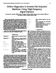
Fig. 6. Simulation results; a) input voltage 𝑣𝐴 [V] and current 𝑖𝐴 ; b) source voltage 𝑣𝑠𝐴 [V] and current 𝑖𝑠𝐴 .
Fig. 7. Simulation results; a) spectrum of input current 𝑖𝐴 ; b) spectrum of source current 𝑖𝑠𝐴 .
The expected relationship is clearly evident between the stator current io and the electrical torque on each machine, where the first increases to satisfy the greater torque that is required. From Figure 6(b) it can be seen that the source voltage and current are in phase, dynamically minimizing the instantaneous reactive power on the input side. This is reflected in a source current in phase with its respective source voltage. But, as there is an unbalanced ac-supply feeding the multidrive system, as expected, the source current is unbalanced in order to accomplish the power balance in the system. As it can be seen in Figure 6, it is evident the effect of the input filter which mitigate high order harmonics as depicted in spectra results showed in Figure 7.
The control scheme can compensate for the unbalanced supply voltages and thus the load voltages and currents remain balanced. The compensation is achieved without any penalty in the transient and steady state operation; moreover, the instantaneous reactive power is minimized.
V. C ONCLUSION In this paper, a technique for predictive control of torque, flux and input power factor was presented for a multi-drive system fed by a six-leg indirect matrix converter operating under unbalanced ac-supply. The algorithm selects the optimum state to be applied at the next sampling instant, based on the minimization of a cost function. Thus, the technique allows for effective monitoring of the speed of each machine to its respective references, excellent monitoring of torque and flux for each machine, and the ability to control the instantaneous power factor with the model of the input filter. The strategy is simple and intuitive to implement, and it only requires a discrete model of the converter and each induction machine.
ACKNOWLEDGMENTS The authors would like to thank the financial support of Basal Project FB0821, the Universidad T´ecnica Federico Santa Mar´ıa and CONICYT Initiation into Research 2012 11121492 Project. A PPENDIX A. Model of the system in state variables The dynamic system model can be represented as: 𝑑 𝑑𝑡 x
= 𝑓 (x, u) = Ax + Bu, y = 𝑔(x, u) = Cx + Du.
(26)
donde: ∙ A is defined as the state matrix of dimension 𝑛𝑥𝑛. ∙ B is defined as the input matrix of dimension 𝑛𝑥𝑚. ∙ C is defined as the output matrix of dimension 𝑝𝑥𝑛. ∙ D is defined as the direct pass matrix of dimension 𝑝𝑥𝑚. After applying algebra to equation (26), and considering a sample time 𝑇𝑠 , the discrete system can be described as: x(𝑘 + 1) = Φ(𝑇𝑠 )x(𝑘) + Γ(𝑇𝑠 )u(𝑘), (27) y(𝑘) = Cx(𝑘) + Du(𝑘),
where,
R EFERENCES Φ(𝑇𝑠 ) = 𝐿−1 {(𝑠I − A)−1 }∣𝑡=𝑇𝑠 = 𝑒A𝑇𝑠 , ∫
Γ(Ts ) =
𝑇𝑠
(28)
Φ(𝑣)𝑑𝑣B = A−1 (Φ − I𝑛𝑥𝑛 )B.
0
(29)
In terms of the state variable filter model, by using equations 𝑇 (7) and (8) to model filter 𝐿𝐶, selecting x = y = [vi is ] as 𝑇 a state and output variable and u = [vs ie ] as an input variable, the system is obtained in state variables for the continuous system, according to equation (30). [ A=
0 − 𝐿1𝑓 [
C=
1 𝐶𝑓 𝑅 − 𝐿𝑓𝑓
1 0 0 1
]
[ ,
B=
0 − 𝐿1𝑓
] ,
D=
[
0
− 𝐶1𝑓 0
] , (30)
0
]
,
According to the above, the continuous system is discretizable for a sampling frequency 𝑇𝑠 , according to the model proposed in (27), and as proposed in the following equations: ] [ Φ1 (𝑇𝑠 ) Φ2 (𝑇𝑠 ) . (31) Φ(Ts ) = Φ3 (𝑇𝑠 ) Φ4 (𝑇𝑠 ) [ Γ(Ts ) =
Γ1 (𝑇𝑠 ) Γ3 (𝑇𝑠 )
Γ2 (𝑇𝑠 ) Γ4 (𝑇𝑠 )
] ,
(32)
B. Simulation parameters Simulation parameters are indicated in Table I. TABLE I S IMULATION PARAMETERS Variables 𝑇𝑠 𝑉𝑠 𝑓𝑠 𝑅𝑓 𝐿𝑓 𝐶𝑓 𝑅𝑑 𝜆 𝜓1 𝜆 𝜓2 𝜆𝑇1 𝜆𝑇2 𝜆𝑞 𝑃𝑛 𝜔𝑛 𝑉𝑛 𝐼𝑛 𝑝 𝑅𝑠 𝐿𝑚 𝐿𝑠 𝐿𝑟 𝐽1 𝐽2
Description Sampling time Source voltage Source frequency Grid resistance Input filter inductor Input filter capacitor Damping filter resistor Stator flux weighting factor machine 1 Stator flux weighting factor machine 2 Torque weighting factor machine 1 Torque weighting factor machine 2 Reactive power weighting factor Nominal power for each machine Nominal speed of each machine Nominal voltage of each machine Nominal current of each machine Poles pair of each machine Stator resistance of each machine Magnetizing inductance of each machine Stator inductance of each machine Rotor inductance of each machine Inertia momentum of machine 1 Inertia momentum of machine 2
Value 10[𝜇s] 763.6[V] 50[Hz] 0.5[Ω] 0.4[mH] 21[𝜇F] 56[Ω] 14000 14000 63 63 0.5 4[𝑘𝑊 ] 149.7[rad/s] 380[V] 12[A] 2 1.35[Ω] 282.2[Ω] 286.13[𝑚𝐻] 286.13[𝑚𝐻] 0.06[𝐾𝑔𝑚2 ] 0.06[𝐾𝑔𝑚2 ]
[1] A. Kaviani, B. Hadley, and B. Mirafzal, “A time-coordination approach for regenerative energy saving in multiaxis motor-drive systems,” Power Electronics, IEEE Transactions on, vol. 27, no. 2, pp. 931 –941, 2012. [2] C. Lim, N. Abd Rahim, W. Hew, and E. Levi, “Model predictive control of a two-motor drive with five-leg inverter supply,” Industrial Electronics, IEEE Transactions on, vol. PP, no. 99, p. 1, 2012. [3] M. Jones, D. Dujic, and E. Levi, “A four-motor drive supplied from a triple three-phase voltage source inverter,” pp. T5–194 –T5–200, 2010. [4] D. Kumar, P. Wheeler, J. Clare, and L. De Lillo, “Experimental evolution of the multi-drive system based on two-stage direct power converter topology,” pp. T5–207 –T5–212, sept. 2010. [5] S. Kouro, P. Cortes, R. Vargas, U. Ammann, and J. Rodriguez, “Model predictive control, a simple and powerful method to control power converters,” Industrial Electronics, IEEE Transactions on, vol. 56, no. 6, pp. 1826 –1838, jun. 2009. [6] H. Miranda, P. Cortes, J. Yuz, and J. Rodriguez, “Predictive torque control of induction machines based on state-space models,” Industrial Electronics, IEEE Transactions on, vol. 56, no. 6, pp. 1916 –1924, jun. 2009. [7] P. Correa, J. Rodriguez, M. Rivera, J. Espinoza, and J. Kolar, “Predictive control of an indirect matrix converter,” Industrial Electronics, IEEE Transactions on, vol. 56, no. 6, pp. 1847 –1853, 2009. [8] J. Rodriguez, J. Kolar, J. Espinoza, M. Rivera, and C. Rojas, “Predictive torque and flux control of an induction machine fed by an indirect matrix converter,” in Industrial Technology (ICIT), 2010 IEEE International Conference on, 2010, pp. 1857 –1863. [9] C. Xia, Y. Wang, and T. Shi, “Implementation of finite-states model predictive control for commutation torque ripple minimization of permanent magnet brushless dc motor,” Industrial Electronics, IEEE Transactions on, vol. PP, no. 99, p. 1, 2012. [10] R. Carlson, M. Lajoie-Mazenc, and J. Fagundes, “Analysis of torque ripple due to phase commutation in brushless dc machines,” Industry Applications, IEEE Transactions on, vol. 28, no. 3, pp. 632 –638, may/jun 1992. [11] S. Davari, D. Khaburi, and R. Kennel, “An improved fcs-mpc algorithm for an induction motor with an imposed optimized weighting factor,” Power Electronics, IEEE Transactions on, vol. 27, no. 3, pp. 1540 – 1551, march 2012. [12] J. Rodriguez, J. Kolar, J. Espinoza, M. Rivera, and C. Rojas, “Predictive torque and flux control of an induction machine fed by an indirect matrix converter,” pp. 1857 –1863, march 2010. [13] H. Miranda, P. Cortes, J. Yuz, and J. Rodriguez, “Predictive torque control of induction machines based on state-space models,” Industrial Electronics, IEEE Transactions on, vol. 56, no. 6, pp. 1916 –1924, 2009.