15th International Power Electronics and Motion Control Conference, EPE-PEMC 2012 ECCE Europe, Novi Sad, Serbia
Predictive Load Voltage and Capacitor Balancing Control for a Four-Leg NPC Inverter l 1 2 2 M. Rivera , J. Rodriguez , V. Yaramasu and B. Wu , (1) Ryerson University, Toronto, ON M5B 2K3 CANADA Phone: 416-979-5000 x 6484, Fax: 416-979-5280, Email:
[email protected], URL: http://www.ee.ryerson. ca/ (1) Universidad Tecnica Federico Santa Maria, Av. Espana 1680, Valparaiso, CHILE Phone: +56-32-265-4000, Fax: +56-32-265-4000, Email:
[email protected], URL: http://www. usm.cl
Ahstract-This paper presents a predictive voltage control strategy to control the three-phase four-leg neutral-point-c1amped (NPC) inverter with an output LC filter. The four-leg NPC con verter is developed to deliver power to the unbalanced/nonlinear three-phase loads and it can produce three output voltages independently with one additional leg. The proposed method uses the discrete model of the inverter and load to predict the future load and capacitor voltage behavior for each valid switching state of the converter. The control method chooses a state which generates minimum error between the output voltages and their references and as well as between the capacitor voltages. The feasibility of the proposed predictive voltage control scheme is verified by computer simulations, showing good performance and the capacity to compensate disturbances while maintaining the balance of the dc-link capacitor voltages.
Index Terms-Predictive control, Four-leg converters, Three level four-leg converters, NPC inverter.
I.
I NTRO D UCT I O N
The diode-clamped multilevel inverter employs clamping diodes and cascaded dc capacitors to produce ac voltage waveforms with multiple levels [1]. The inverter can gener ally be configured as a three-, four-, or five-level topology, and the three-level inverter, often known as a neutral-point clamped (NPC) inverter, has found wide practical application, especially in medium voltage (MV) variable-speed drives [2], [3]. Recently three-phase four-wire systems are selected by most utilities in North America as the medium voltage distribution systems [6]. Multilevel inverters are most suitable for such medium voltage, high power applications, because of many attractive features like high voltage capability, reduced common mode voltages, near sinusoidal outputs, low dv / dt 's and smaller or even no output filter. The conventional three-leg neutral-point-clamped inverters are not suitable for three-phase four-wire systems with unbal anced/nonlinear loads because of the following reasons: (i) insufficient dc-link utilization, (ii) high ripple on dc-link capacitors, (iii) problem of dc-link capacitor voltage balance. The four-leg NPC is a promising topology compared to three-leg NPC in three-phase four-wire systems and it offers full utilization of the dc-link voltage and lower stress on the dc-link capacitors [7]. Moreover, reliability of the system
978-1-4673-1972-0112/$31.00 ©2012 IEEE
and the control of the neutral-point voltage during fault-free operation can be improved by using four-leg NPC inverter [8], [9]. A great variety of modulation methods available for this converter can be classified as, pulse width modulation (PWM) [8] - [12] and 3D space vector modulation (SVM) [4], [5], [7], [13]. In contrast to PWM, the complete utilization of the converter capacity to deliver output voltage can be achieved by using SVM. Predictive control is a class of controllers that have found recent application in power electronics [14], [25]. This control appears as an attractive alternative to classical modulation methods, due to its fast dynamic response and simple concept. Since power converters have a discrete nature, the application of predictive control constitutes a promising and better suited approach as compared to the standard schemes that use mean values of the variables. This technique utilizes a very intuitive control law to deal with the multivariable cases, treatment of the constraints, and compensation for dead time [15]. A great variety of control algorithms have been presented under the name of predictive control. Applications of the predictive control for two-level inverters have been reported since the 1980s [15], [17], [20], [21], [24], but nowadays it is possible to find a wide range of applications in power electronics and machine control [16]-[22], [25]. The finite control set model predictive control with a prediction horizon of one sample time is a simple and very flexible control scheme that allows easy inclusion of the nonlinearities and constraints in the design of controller. Moreover, this scheme does not require internal current control loops and modulators. In this paper, a predictive strategy is proposed to control the output voltages as well as the balancing of the capacitor voltages of a four-leg NPC inverter, in an easy and intuitive manner. This control scheme uses the load and output LC filter model to predict future load voltage and capacitor voltage behavior for each valid switching state of the converter. II.
T O P OLOGY A N D MAT HEMATICAL M O DEL
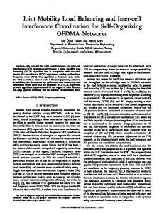
The three-phase four-leg NPC inverter with output LC filter considered in this paper is shown in Fig. 1. This converter presents a connection format similar to the conventional three phase NPC converter, with an additional leg connected to the
DS3c.8-1
P
V,"
1
idc1 Output FilteT
Cdc!
----------------------
0
u
:
iou
I
w
i
f
l
ri
Cdc2 �'
I
Lf
v
idc2
v
Rf
iu
Load
l
i l
VfN
N
Figure I.
I I 0
2Vdc Vdc
o
va
1
_______________________
Three-phase four-leg NPC inverter topology.
Table I POSSIBLE SWITCHING STATES OF THE FOUR-LEG NPC INVERTER.
I o o
Cf
currents (iu, iv and iw), and the voltage levels of the four-leg NPC as follows,
I 0 -I
Kuiu + Kviv + Kwiw, Quiu + Qviv + Qwiw,
(7)
( 8)
where Kx and Qx depend on the voltage levels, such that: neutral point of the load. The voltage in any leg x of the NPC inverter, measured from the negative point of the dc-link (N), is expressed in terms of switching signals as,
where Vdcl and Vdc2 are the dc-link capacitor voltages, and ideally both the capacitors share equal voltages, i.e. (2) The switching signals of each leg of the converter can be represented as follows:
sign{Ln - 1}- sign{Lx - 1}, sign{Ln + 1}- sign{Lx + 1},
where Ln and Lx corresponds to the neutral and phase-levels respectively, and sign is the argument sign, whose value corresponds to 0, 1 or - 1. The RLC filter feeds RL load with a controlled voltage v 0, irrespective of the current io consumed by the load. The load voltage v 0, as a function of the filter parameters, inverter current i and differential NPC voltage v with respect to the negative dc-rail, is given by: di
v 0 = v - Lf t - RfI.· d
(3) (4) All the four legs of the NPC converter provide three voltage levels (Vdc, 0 and -Vdc) with respect to the midpoint of dc link. The switching states to achieve these levels are summa rized in the Table I. The four-leg NPC inverter has a total of 81 possible switching states. The nominal voltages of both capacitors are directly related to the current idcl and idc2 as:
(9) (10)
(11)
The inverter current i as a function of the load current i 0 and the output voltage v 0, are defined as follows, (12) The system in Eq. (11) and Eq. (12) can be represented in state variable form as: (13)
(5) where,
(6) where Cdcl and Cdc2 are the dc-link capacitors. Moreover, these capacitor currents are directly related to the three-phase
A
DS3c.8-2
[
0
- - 1/ Lf _
dc-Link 4-Leg NPC
RLC
Load
Filter
follows:
T [ide1 ide2] , T [Vdcl Vde2] ,
(22) (23)
where the dc-link current are calculated using equations (7), (8), (9) and (10). S[k]
8
c.
Minimization of cost function 9 wit h l4--- v�[k + I] (24), 2( 5) and (26) 81
o[k + I] 81
vdc[k + I]
k] ....-.."... - ......,.,......,..."...-,+_vdc[ .Predictions of vo[k] Vo and V(le, using . [k] L...-----1J.(1!25:1.),J.(�16:2. d .l(2�ll ) an ) .1-� �
:[k;
Figure 2.
III. A.
PROP OSED P REDIC T I V E C O NTROL SC HEME
Control Strategy
Predictive Models
As shown in Fig. 2, the cost function requires predicted out put voltages (v o[k+ 1]) and the capacitor voltages (v dedk+ 1] and Vde2[k + 1]) in discrete-time form. For this reason, the system in (13) is represented in the discrete-time form as follows: =
[ ilk] ] + [ioV[[k]k]] ,
..To.. Yolk] '¥
r
(1S)
where
and where the voltage and current vectors are defined as:
V
[VuN - VfN
io
[iou [iu
Vo
gl g2
Block diagram of predictive control scheme for the 4-leg NPC .
[Yolilkk++1]1]]
[vou
Zow
Zov iv
VvN - VfN ·
Zw
Vov
·
r,
r,
VwN - VfN
r , (17) (18) (19)
T
vow] .
gl + g2 Ilv o[k + 1]* - Yolk + 1]111, plvdcl[k + 1]- Vde2[k + 1]1,
9
The predictive control scheme is shown in Fig. 2. The algorithm calculates all the 81 possible conditions that the state variables can achieve during the future sample k+ 1. The control strategy chooses a switching state in the sampling instant k, which minimizes the cost function in the k+1 sampling instant. The system applies this switching state during the whole k+1 sampling period. B.
Cost Function
As shown below, the cost function considered in this paper has two objectives: the minimization of error between the pre dicted output voltages v o[k+ 1] and their references v�[k+ 1], and the balance of the dc-link capacitor voltages. These two control objectives are represented, with the following equations
(20)
The capacitor voltages can be represented in discrete-time form as: Ts (21) i dc[k], vde[k + 1] = v de[k] + c de whereTs is the sampling time, and Cdc is the dc-link capacitor. The dc-link current and voltage vectors are represented as
(24) (2S) (26)
where p is a weighting factor, which can be adjusted according to the desired performance. The switching state that minimizes the cost function is chosen and then applied at the next sampling instant. Additional constraints such as switching frequency reduction, current limitation and spectrum shaping can be included just by adding those conditions to the cost function. IV.
S IM ULAT I O N RES ULTS
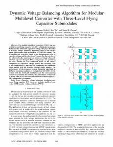
To validate the proposed control method, a simulation model of a three-phase four-leg NPC inverter with the parameters as indicated in Table II has been developed with a sample time ofTs = 20[ps] and a three-phase resistance as an output load. As shown in Fig. 3, a step change in the load resistance in phases u and w, of 2 p.u. and 2/3 p.u. respectively, has been applied to t =O.IS[s], without any alterations in the controller (no information of a change in parameters is provided to the controller). The neutral current i f whose value corresponds to the sum of three-phase currents is shown in Fig. 3d, while Fig. 3a shows the output voltage, which is not distorted, even in the load step. The balancing of the capacitor voltages (V dcl and Vde2) is shown in the Fig. 3c, where the difference between the capacitor voltages is almost negligible (8 [VD, even with the sinusoidal dc-link disturbance, and the unbalanced load with neutral currents. Fig. S shows the behavior of the system, applying, in t =O.IS[s], a connection step change of a non-linear load, which consists of a diode rectifier connected to a RL load, as shown in Fig. 4, where the neutral leg is connected directly to the negative terminal of the load. In this case, the weight factor p of the cost function is modified for a better performance in the output voltage and the dc-link balance. The load current is shown in Fig. Sa, whose waveforms have a continuous component, due to the rectification effect, while Fig Sa shows the output voltage, noting that there is no appreciable distur bance in the connection step. The balancing of the capacitor voltages (Vdcl and Vde2) is shown in Fig. Sc, where the voltage
DS3c.8-3
• ... ... . ... ... ... .... ... . . ... ... .... . ......... .... • . 20 . iou . 1 .••.•• ..• ...••• • • : � � T . == !:: •• . :: -10 , .... . ........: .. ....... , ..... : .. .. ...... , .. ...� ... . ....... .. ,:.... ., , .... .: . . . .........:.. ...... , ., .....�... ........... , .. : -20 0.18 0.11 0.12 0.13 0.14 0.16 0.17 0.19 0.15 (a) . . . . . . . . . .. . . . . . . . . . . . . . . 400 20 .
. . .
. . . . . . .
. . . . . . .
... ... ... ...•....
. .
. . . . . . .
"
"
"
. . .
:
. .
___
' ''' '''
-200 ....... .. ........•.. ....... .. ........ .. ....... .. ....... .. ....... .. .•........ ....... .• ....... . .......•.. ..... .. . ......•.. .. ....... .. ...• ----�-----�-----�-----�-----�----� -4000.11� 0.12 0.13 0.14 0.15 0.16 0.17 0.18 0.19 (b) 305 . . .
. . .
. . .
. . .
.
•
.
.
.
. . .
. . .
. . .
.
,
. .
. . . . . .
. .
. .
,
. .
. . .
. .
. . .
.
.. . .
. .
. . .
. . .
.
.
.
. .
. .
.
. . .
. .
. .
. . .
. .
.
: ...••. . ••••• ..••..••:••. • ...•...••••• ..••:: .•...•••••• :: .......... ........ ............ . : ••..••••• ..••.•.• • •••.•.••..•••••. .•..•
�
o
.
.
.
0.15
0.16
0.17
0.16
0.17
.
�
u
" �
295 0.11
0.12
0.14
•••
c( )
_
0.12
__
0.13
,
__
0.14
. .
�:: . •:
. . . .
. . .
.
�
.............,.'--- .............'--.......... j"'-------; -
;:j[r--_ 0.11
0.13
.
0.15
t [s] (d)
0.18
0.19
Figure 3. Simulation results for the predictive control of four-leg NPC inverter: (a) output currents; (b) output voltages; (c) dc-link voltages; (d) neutral output current.
u
discussion of the control strategy, implementation issues and simulation results will be provided in the final version of the paper.
v w
ACKN OWLEDGMENT
The authors wish to thank the financial support from the Natural Sciences and Engineering Research Council of Canada (NSERC) through Wind Energy Strategic Network (WESNet) Project 3.1, and Basal Project FB0821.
n
Figure 4.
Topology of the non-linear load used in the simulation.
difference is very small, even with the neutral current shown in Fig. 5d, which has a notorious continuous component. V.
C O NCL US I O N
A finite control set model predictive control strategy with a prediction horizon of one sample time has been proposed in this paper to control the three-phase four-leg NPC inverter with an output LC filter. The control algorithm tests each of the 81 possible switching states and then chooses a switching state that minimizes the cost function. The ideal minimum of the cost function is zero and represents the perfect regulation of the output voltages with the balancing of the capacitor voltages. With the predictive control, (a) balancing of the dc link capacitor voltages and (b) tracking of the output line voltage to its reference with less error has been achieved under the balanced and un-balanced load conditions. A deeper
RE FERENCES [I] B.K. Bose, Power Electronics and Motor Drives: Advances and Trends, Academic Press, 2006. [2] B. Wu, High-Power Converters and AC Drives, Wiley-IEEE Press, 2006. [3] B. Wu, Y. Lang, N. Zargari, S. Kouro Power Conversion and Contorl of Wind Energy Systems, Wiley-IEEE Press, 2011. [4] Alahuhtala, J.; Tuusa, H.; , "Space Vector Modulated and Vector Con trolled Three-Level Four-Wire Unidirectional AC-DC-AC Converter," P ower and Energy Conference, 2008. PECon 2008. IEEE 2nd Interna tional , vol., no., pp.781-786, 1-3 Dec. 2008. [5] Ning-Yi Dai, Man-Chung Wong, Ying-Duo Han, Application of a Three Level NPC Inverter as a Three-Phase Four-Wire Power Quality Compen sator by Generalized 3DSVM," Power Electronics, IEEE Transactions on , vol.2I, no.2, pp. 440- 449, March 2006. [6] Ning-Yi Dai, Man-Chung Wong, Fan Ng, Ying-Duo Han, A FPGA-Based Generalized Pulse Width Modulator for Three-Leg Center-Split and Four Leg Voltage Source Inverters, IEEE Trans. on Pow. Electronics, vol. 23, no 3, May. 2008, pp. 1472-1484. [7] Yao J., Green T., Three-Dimensional Space Vector Modulation for a Four Leg Three-Level Inverter, IEEE European Conf. on Pow. Electronics and Applications, Sep. 2005, Dresden, Germany.
DS3c.8-4
5 0
L �• • �::I - �tttl:tfT;�
"«:
::
·· : · · : · ·· · ·· ·· ·· · · �� · � 0.145· 0.15 0.155 · 0.16 (a)0.165 0.17 0.175 0.18 0.185 0.19
·
·
·
·
·
5OO · : : : . : : : ::,. 0 ··· : · · ·· :: · . : : : : : : : � . : . . . . . . -500 � 0.145 0.15 0.155 0.16 0.165 0.17 0.175. 0.18 0.185 0.19 , o ._
·
.
·
.
. . .
.
:
.
.
.
.
.
.
.
.
:
·
.
.
.
.
: : .: ... :
.
.
. .
.
.
.
.
.
.
.
:
.
.
. . .
.
.
.
•
.
.
.
•
- Vou - Vov
: .. : ... : . .: :
. .
:
.
- Vow
.
.
.
. .
. .
.
.
.
(b)
0.145 0.15 0.155 0.16 (c)0.165 0.17 0.175 0.18 0.185 0.19 . .....................• . ...... 15 . • . .. _"«: 10 " . :. .: . ···c · ·· .: . : . . . . • : : : 5. . . . . :? o L-_�� t t : ·: t·· 0.145······0.15.L················: 0.155 0.16·········0.165·········0.17··· 0.175 0.18 0.185 0.19
�:� � "
.
:
'
:
·
�
based on a Three-Dimensional PWM Algorithm, IEEE Conf. on Electric Utility Deregulation and Restructuring and Power Technologies DRPT 2008, Apr. 2008, Nanjing, China.
·
�
-i
�
�
..
.
:
-L
-L
�
____ __ __ __ __ __ __ __ ___
t [sl (d)
[12] Kim J., SuI S., Enjeti P., A Carrier-Based PWM Method with optimal Switching Sequence for a Multilevel Four-Leg Voltage-Source Inverter, IEEE Tran. on Ind. Applications, vol. 44, no. 4, Jul.-Aug. 2008, pp. 12391248. [13] Dai N., Wong M., Han Y., Application of a Three-level NPC Inverter as a Three-Phase Four-Wire Power Quality Compensator by Generalized 3DSVM, IEEE Tran. on Pow. Electronics, vol. 21, no. 2, Mar. 2006, pp. 440-449. [14] Cortes P., Kazmierkowski M., Kennel R., Quevedo D., Rodriguez J., Predictive Control in Power Electronics and Drives, IEEE Trans. on Industrial Electronics, vol. 55, no. 12, pp. 4312-4324, Dec. 2008. [15] Rodriguez J., Pontt J., Silva c., Correa P., Lezana P., Cortes P., Ammann U., Predictive Current Control of a Voltage Source Inverter, IEEE Trans. on Industrial Electronics, vol. 54, pp. 495-503, Feb. 2007. [16] Correa, P., Rodriguez, J., Lizama, I., Andler, D., Predictive Control Scheme for Current-Source Rectifiers, Industrial Electronics, IEEE Trans actions on , vo1.56, no.5, pp.1813-1815, May 2009. [17] Cortes, P., Ortiz, G., Yuz, J.I., Rodriguez, J., Vazquez, S., Franquelo, L.G., Model Predictive Control of an Inverter With Output LC Filter for UPS Applications, Industrial Electronics, IEEE Transactions on , vol.56, no.6, pp.1875-1883, June 2009.
Figure 5. Simulation results for the predictive control of four-leg NPC inverter using a nonlinear load: (a) output currents; (b) output voltages; (c) dc-link voltages; (d) neutral output current.
[18] Miranda, H., Cortes, P., Yuz, J.I., Rodriguez, J., Predictive Torque Control of Induction Machines Based on State-Space Models, Industrial Electronics, IEEE Transactions on , vo1.56, no.6, pp.1916-1924, June 2009.
[8] Ceballos S., P ou J., Robles E., Zaragoza J., Ibanez P., Martin J.L., Fault Tolerant Hybrid Four-Leg Multilevel Converter, IEEE European Conf. on Pow. Electronics and Applications, Sep. 2007, Aalborg, Denmark. [9] Ceballos S., P ou J., Zaragoza J., Martin J.L., Robles E., Gabiola I., Ibanez P., Efficient Modulation Technique for a Four-Leg Fault-Tolerant Neutral Point-Clamped Inverter, IEEE Tran. on Ind Electronics, vol. 55, no. 3, Mar. 2008, pp. 1067-1074. [10] Wong M., Tang J., Han Y., Cylindrical Coordinate Control of Three Dimensional PWM Technique in Three-Phase Four-Wire Trilevellnverter, IEEE Tran. on Pow. Electronics, vol. 18, no. I, Jan. 2003, pp. 208-220. [II] Yang X., Zhang Y., Zhong Y., Three-Phase Four-Wire DSTATCOM
[19] Correa, P., Rodriguez, J., Rivera, M., Espinoza, J.R., Kolar, J.w., Predictive Control of an Indirect Matrix Converter, Industrial Electronics, IEEE Transactions on , vo1.56, no.6, pp.1847-1853, June 2009.
Table II VALUES USED IN THE FOUR-LEG N P C INVERTER AND LOAD.
Variables
Description
Vdc
In
dc-link voltage dc-link capacitor dc-link noise amplitude dc-link noise frequency
Lf Rf Cf
Filter inductor Filter resistor Filter capacitor
RL LL Iref Aref
Load resistance Load inductance Output reference frequency Output reference amplitude
Ts p p
Sampling time Weighting factor (linear load) Weighting factor (non-linear load)
Cdc An
Values [VI [/l-F] 0.01 [V] 100 [Hz] 300
[20] Yaramasu, Y., Rodriguez, J., Wu, B., Rivera, M., Wilson, A, Rojas, C., A Simple and Effective Solution for Superior Performance in Two-Level Four-Leg Voltage Source Inverters: Predictive Voltage Control, Industrial Electronics (ISlE), 2010 IEEE International Symposium on , vol., no., pp.3127-3132, 4-7 July 2010. [21] Rodriguez, J., Wu, B., Rivera, M., Rojas, c., Yaramasu, Y., Wilson, A, Predictive Current Control of Three-Phase Two-Level Four-Leg Inverter, P ower Electronics and Motion Control Conference (EPE/PEMC), 2010 14th International , vol., no., pp.T3-106-T3-IIO, 6-8 Sept. 2010. [22] Rodriguez, J.; Bin Wu; Rivera, M.; Wilson, A; Yaramasu, Y.; Rojas, c., "Model predictive control of three-phase four-leg neutral-point-clamped inverters," Power Electronics Conference (lPEC), 2010 International , vol., no., pp.3112-3116, 21-24 June 2010.
1000
[mH] [0] 80 [/l-F] 2
[23] Rivera, M., Rodriguez, J., Wheeler, P.w., Rojas, C.A, Wilson, A, Espinoza, J.R., Control of a Matrix Converter With Imposed Sinusoidal Source Currents, Industrial Electronics, IEEE Transactions on , vo1.59, no.4, pp.1939-1949, April 2012.
0.05
[0] [mH] 60 [Hz] 280 [V] 20
10
20
[/l-s]
0.15
[24] Wirslin R., Pulsumrichtergespeiste Synchronmaschinen Antrieb mit Ho her Takifrequenz und Sehr Grof3em Feldschwachbereich, Dissertation Universitt Stuttgart, 1984. [25] Kouro S., Cortes P., Vargas R., Amman U., Rodriguez J., Model Predictive Control - A Simple and Powerful Method to Control Power Converters, IEEE Trans. on Industrial Electronics, vol. 56, issue 6, Jun. 2009, pp 1826-1838.
0.3
DS3c.8-5