Mater. Res. Express 5 (2018) 012001
https://doi.org/10.1088/2053-1591/aaa04c
TOPICAL REVIEW
RECEIVED
9 November 2017 REVISED
29 November 2017
Predictive modeling of solidification during laser additive manufacturing of nickel superalloys: recent developments, future directions
ACCEPTED FOR PUBLICATION
8 December 2017 PUBLISHED
4 January 2018
Supriyo Ghosh1 Materials Science and Engineering Division, National Institute of Standards and Technology, Gaithersburg, MD 20899, United States of America 1 Guest Researcher. E-mail:
[email protected] Keywords: additive manufacturing, solidification, metals, nickel superalloys, modeling and simulation
Abstract Additive manufacturing (AM) processes produce parts with improved physical, chemical, and mechanical properties compared to conventional manufacturing processes. In AM processes, intricate part geometries are produced from multicomponent alloy powder, in a layer-by-layer fashion with multipass laser melting, solidification, and solid-state phase transformations, in a shorter manufacturing time, with minimal surface finishing, and at a reasonable cost. However, there is an increasing need for post-processing of the manufactured parts via, for example, stress relieving heat treatment and hot isostatic pressing to achieve homogeneous microstructure and properties at all times. Solidification in an AM process controls the size, shape, and distribution of the grains, the growth morphology, the elemental segregation and precipitation, the subsequent solid-state phase changes, and ultimately the material properties. The critical issues in this process are linked with multiphysics (such as fluid flow and diffusion of heat and mass) and multiscale (lengths, times and temperature ranges) challenges that arise due to localized rapid heating and cooling during AM processing. The alloy chemistry-process-microstructure-property-performance correlation in this process will be increasingly better understood through multiscale modeling and simulation.
1. Introduction The production of metallic parts via additive manufacturing (AM) processes (for recent reviews, see [1–3]) such as laser powder bed fusion and direct metal laser sintering is growing rapidly to achieve the ever-increasing demand for improved strength and resistance to creep and fatigue for aerospace, defense, and medical applications [4–6]. Ni-based superalloys in this context possess excellent mechanical properties at elevated temperatures, making them essential to the above sectors. However, there is a lack of confidence in the quality of additively manufactured parts due to the inherent multiscale and multiphysics problems associated with processing. On a macroscopic scale, i.e. millimeters, as the laser rasters across the powder bed, local regions begin to melt resulting in a molten pool of certain dimensions. The molten pool then undergoes a solidification, remelting and subsequent additional solidification processes driven by the resultant complex thermal history due to repeated passes of the laser. Temperature is highest at the top surface and varies along the depth, width and length of the melt pool. Therefore, the melt pool represents different local solidification conditions. As these local conditions vary, the microstructures within the solidified puddle also vary in different locations. The uncertainties in the quality of the parts arise precisely due to those location specific complex microstructures and due to unpredictable microstructure evolution paths, leading to beneficial or detrimental phases and microstructural anisotropies due to segregation and orientations [1, 5, 7–9]. These issues have received little attention, but they are important to consider during AM solidification.
© 2018 IOP Publishing Ltd
Mater. Res. Express 5 (2018) 012001
S Ghosh
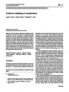
Figure 1. (a) Typical melt pool shapes are shown for the consideration of different physics within the melt pool (reproduced from [10], with permission from Elsevier). (b) Typical solidification boundary is illustrated from which the local solidification conditions are estimated (reproduced from [17], open access). Melt pool solidify into columnar (on the side) and equiaxed (bottom) dendritic microstructures. (c) Phase-field simulation predicts a typical columnar dendritic morphology. The colors represent spatial solute concentration variation. Solute enriched droplets pinch off from the dendrite roots, where the secondary solid phases form. (d) Typical snapshot of a solid–liquid interface in thermal equilibrium during MD simulation is shown (reproduced from [18], with permission from Elsevier).
The new classes of AM materials are substantially different than those produced by traditional casting, mechanical working and final machining mechanisms. This is due to the rapid solidification processing (RSP) during AM, leading to non-equilibrium segregation of the alloy elements in the molten pool, making the quantification of the resulting microstructures difficult. The prediction of material properties therefore becomes a serious hurdle, resulting in a lack of confidence in the quality of the final part. Some 47% of manufacturers surveyed indicated that the uncertain quality of the final product was a barrier to adoption of AM [10–12]. A predictive multiscale modeling framework could optimize the AM process parameters to improve the likelihood of producing qualified parts. Due to the high temperature and small volume of the molten pool, in situ measurements of the solidification conditions are difficult. Numerical simulations of the laser deposition process is a viable alternative to obtain the local solidification conditions in the melt pool. A finite element analysis (FEA) method, which includes heat transfer, fluid flow, Marangoni convection and other hydrodynamic effects [12, 13], can simulate realistic melt pool shapes as well as temperatures. Energy balance equations on the macroscale are solved in ABAQUS [14]/ ANSYS [15]/COMSOL [16] environment to obtain the temperatures and geometries in the melt pool (refer to figure 1(a)). Laser processing parameters such as the laser power, speed, and size control the dimensions of the melt pool. These dimensions are important as they determine the density of the final parts through the solidification microstructures as well as through the cooling rates; for example, with increasing laser power or reduced laser speed, the melt pool becomes deeper [10, 12]. Solidification conditions therefore change along the melt pool solid–liquid boundary and influence the resulting microstructure formation. For the microstructure simulations, phase-field models [19–21] have been the most popular choice. In these models, a scalar-valued order parameter field f is introduced to distinguish the phases present in a microstructure: if liquid is defined by f = -1 and solid by f = 1, then the interface can be taken as the f = 0 contour. Therefore, explicit tracking of the interface is no longer needed, and one can simulate the complex solid–liquid interface in an efficient way. Phase-field equations of motion are essentially time-dependent partial differential equations, which are solved by efficient numerical methods to obtain the steady state composition, temperature and order parameter maps through the solution of diffusion of heat, composition, and order parameter fields. The microstructures simulated in this way correspond only to a particular location in the melt pool. During the course of phase-field simulations, melt pool often solidifies into columnar and/or equiaxed dendritic microstructures. These microstructures often contain defects such as microporosity and solidification and liquation cracks, microstructural anisotropies due to alloy chemistry, segregation and orientations of the solidifying dendrites, and residual stresses due to shrinkage during terminal solidification. These complex features within the microstructure collectively influence the properties and performance of the solidified 2
Mater. Res. Express 5 (2018) 012001
S Ghosh
material. These effects have yet to be explored for AM solidification. Simulation of these aspects may require considerable computation time. Fortunately, phase-field models are found to scale well in parallel environments (MPICH [22], OpenMP [23] and CUDA [24]) to run the simulation codes faster. The phase-field model parameters are approximated to behave quantitatively only at small-valued solidification conditions [25]. Better models are therefore needed to treat larger values of the melt pool solidification conditions, appropriate for AM. For more accurate modeling of the melt pool solidification, realistic solid–liquid interface properties are also needed. Molecular dynamics (MD) simulation can provide the information regarding the interfacial energy anisotropy and the interfacial kinetic coefficient for metallic alloys in AM solidification regime. Such an efficient combination of finite element, phase-field, and MD approaches could potentially capture the predictive AM microstructural evolution. The present overview is aimed at the following outstanding issues that arise due to the multiscale, multiphysics nature of the solidification in the melt pool.
2. Macroscale: FEA FEA simulations determine the actual solidification conditions in the melt pool. Using a suitable commercial software, a FEA model generate the global temperature history during laser irradiation on a single/multi layer(s) of powder of finite thickness deposited on a solid substrate of the same base alloy [26, 27]. Ni-based superalloys have been commonly used for the powder as well as the substrate properties in these simulations. Bulk material properties, such as latent heat, density, and specific heat, were estimated from CALPHAD-based thermodynamic calculations [28–30]. To reduce computational time, the FEA mesh elements that interact with the laser beam were finely meshed, and a coarse mesh was used in the far-field. Heat input from the laser was approximated in the literature by a moving point, line or plane heat source [31], a double ellipsoidal volumetric heat source [32], or a Gaussian source [7, 33]. Both convective and radiative heat losses were considered in these studies. The temperature distribution as a function of time was obtained by solving equations for the conservation of energy. The computed results are generally visualized using the appropriate visualization module of the FEA software or using a custom MATLAB [34]/PARAVIEW [35] program. The temperature gradient at each FEA element was estimated by the magnitude along the Cartesian directions using the temperature values from the neighboring elements. The trailing edge of the melt pool in experiments represents the solid–liquid boundary (refer to figure 1(b)), which was approximated by the melting temperature isotherm. Solidification begins at this boundary and the resulting columnar microstructures grow roughly perpendicular to this boundary [26, 27]. The curvature of this boundary introduces an angle, which correlates the beam speed with the local solidification velocity. The solidification boundary represents different temperature gradients and solidification rates. Typically in simulations, the temperature gradient varies between ≈105 and 107 K m−1 and the solidification rate varies between ≈0.01 and 0.5 m s−1 for a laser scan speed on the order of 1 m s−1 [26, 27]. Temperature gradient times the solidification velocity is the cooling rate. These local parameters were provided as inputs to the phase-field model in order to simulate location specific microstructures. A wide range of transient non-equilibrium physical phenomena take place within the molten pool (refer to figure 1(a)). Some of these phenomena are fluid flow, Marangoni convection, keyhole mode melting, gravity forces, and recoil pressure due to any evaporation heat losses [10–12]. A more realistic result can be obtained when all of these complex phenomena are considered. However, this will bring an additional cost, e.g. long computational time and more computational resources. Implementing heat transfer, fluid flow, and Marangoni convection in the melt pool could be a suitable first approach [7, 10, 12]. The resulting mass, momentum, and energy conservation equations can be solved at each discrete element to obtain the transient thermal profiles. For validation of the model, single-track laser scan simulations [36] can be used to generate melt pools with certain dimensions along with the temperature profiles which can be compared with in situ thermography measurements [27]. The solidification conditions, for example the cooling rate varies between 103 and 106 K s−1 in different studies due to different approximations of the melt pool physics. An unified modeling approach is therefore needed to quantify the contribution of each melt pool physics and their interactions.
3. Nanoscale: MD Crystal-melt free energy calculations can be performed using suitable interatomic potentials for AM alloys of interest ([18] and the references within). MD simulations, via the LAMMPS [37] software package, are generally conducted to assess the solid–liquid interfacial free energy and kinetic coefficient via a capillary fluctuation technique which monitors the amplitude of atom fluctuations in the interface position [18] (refer to figure 1(d)). Interface properties data are still rare for the solidification conditions relevant to AM regime for multicomponent alloys. Atomistic simulations were also used to estimate the diffusivity of the liquid and the partitioning of the solute across a solid–liquid interface during non-equilibrium rapid directional solidification 3
Mater. Res. Express 5 (2018) 012001
S Ghosh
[38, 39]. MD Simulations can help to estimate the parameters that characterize a solid–liquid interface in AM regime. Recently, MD simulations were performed on a stable aluminum solid–liquid interface under rapid solidification conditions and it was found that the interfacial free energy increased by a factor of 1.25 as the temperature gradient increased by a factor of 3, while the interface anisotropy parameter remained independent of the solidification conditions [40]. The interfacial properties of multicomponent alloys under nonequilibrium conditions need to be calculated in MD for use in the phase-field model.
4. Mesoscale: phase-field Phase-field models use the FEA simulated melt pool solidification conditions and the MD simulated solid– liquid interface information to simulate the solidification microstructures. AM alloys of interest, for example Inconel 718, are typically multicomponent alloys with over a dozen elements. A three component analog, for example Ni−Cr−Nb, may describe the alloy 718 effectively. It is noteworthy to mention that the design of a ternary AM alloy depends on the microstructural features of interest; two classes of alloys are possible which include either the positive segregation elements (equilibrium partition coefficient > 1) such as Ti, Mo, and Nb in Inconel 718 or the negative segregation elements (equilibrium partition coefficient < 1) such as Fe and Cr. In the former class of alloys, the γ-dendrite will be lean in Ti, Mo, and Nb and the liquid will be enriched with these elements as the solidification proceeds, while solute partitioning occurs in the opposite direction in the later. A multicomponent phase-field formalism [21, 41–44] can be adopted which combines the chemical bulk free energy, the interfacial free energy, and the driving forces for phase transformations such as lowering of the chemical potential. The resultant free energy functional is then minimized using standard variational derivatives with respect to the microstructure field variables, i.e. composition, temperature, and order parameter. The resulting time-dependent equations are known as the Cahn–Hilliard equation [45] which describes the temporal evolution of the conserve quantity composition and the Allen–Cahn equation [46] or the time dependent Ginzburg–Landau equation which describes the temporal evolution of the non-conserved quantity order parameter [19–21]. These partial differential equations are solved in 2D/3D on a uniform/adaptive mesh, using the finite difference/finite volume method, and explicit/semi-implicit time stepping scheme. Simulations often begin with either a thin layer or a circular solid seed in the supercooled liquid at the bottom of the simulation box with relevant initial and boundary conditions and with random, small amplitude perturbations. Stable perturbations grow with time and break into steady state dendritic microstructures (refer to figure 1(c)). For equiaxed mode of solidification, nucleation mechanisms need to be incorporated in the phase-field equations [47]. Software packages such as MATLAB [34], PARAVIEW [35], GNUPLOT [48] are generally used to visualize and analyze those complex morphologies in the following facets, which need further attention. 4.1. Dendrite properties The size, shape and distribution of dendrites are different at different locations in the melt pool. Phase-field simulations for AM solidification conditions often result in columnar dendrites with primary arms with average spacing ≈1.0 μm and secondary sidearms with average spacing ≈0.5 μm [1, 26]. These spacings control the material properties, such as yield strength and tensile strength. A prediction of these spacings from the microstructure simulations and subsequent comparison with the experiments and dendrite growth theories are therefore essential. This comparison can be used, for example, as a standard reference spacing data for Ni-based superalloys for AM solidification. Fourier analysis and other methods [49] can be used to extract the dominant spacings in the microstructure. These results will be significant, since current understanding is still largely limited to low-velocity casting solidification regime. Moreover, dendrite spacing varies significantly in the presence of melt pool convection, and thus needs to be studied in AM regime [50]. 4.2. Microstructural anisotropies RSP leads to non-equilibrium partitioning of solute atoms in the solid and liquid. As a result, solute gets segregated in the volume of liquid that solidifies in the spaces between the already solidified dendrites and gets enriched by ≈2–5 times of the nominal composition of the alloy element with the progress of solidification [26, 27]. This is known as microsegregation [51]. The presence of multiple elements in the liquid makes the elemental segregation in the interdendritic regions complex. Moreover, the orientation/texture of the growing dendrites is often different in different locations within the melt pool, depending on the direction of the temperature gradient/heat flow. Anisotropy in orientations (the change in preferred orientation with respect to the growth direction), leading to intrinsic anisotropy in the mechanical properties, is therefore natural to consider. An anisotropic gradient energy surface tension [52, 53] in the phase-field free energy functional and a rotation matrix representation [52, 53] for the normal vector components of the solid–liquid interface can suitably describe the orientation selection during solidification [52, 53]. Simulations can also be performed in 4
Mater. Res. Express 5 (2018) 012001
S Ghosh
single/bicrystals in which the misorientation angles and the convergent/divergent growth conditions between columnar dendrites are considered as solidification variables. In this context, the competition and the transition between the columnar and the equiaxed growth modes of dendrites were also modeled using phase-field [47] or stochastic analyses [54], but in the low-velocity limit. A quantitative description of these phenomena in the highvelocity limit will be a significant step towards microstructure and property control, since this knowledge is required to perform the solid-state homogenization heat treatment. A material with uniform properties will therefore be designed and controlled. 4.3. Solidification defects A prediction of the solidification defects such as microporosity, solidification cracking, and residual stresses in the semisolid mushy zone during the late stages of solidification is very important, which have yet to be explored for AM solidification. The mushy zone in columnar dendrites is a two-phase solid and liquid coexistence region between the fully solid and the fully liquid states where majority of the solidification defects form. Those defects arise due to random growth of the solid dendrites toward each other and finally coalesce, leading to insufficient feeding of the liquid to accommodate shrinkage. As the fraction of solid in the mushy zone increases to ≈0.6–0.98 [49, 55], the liquid is not able to flow freely and compensate for shrinkage, resulting in microporosity. The semisolid mushy zone therefore becomes weak and ruptures when stressed. This phenomenon is known as hot tearing. This behavior can be quantified by extracting the fraction of solid and liquid from either the simulation data or the Scheil solidification approximation [49, 55] and making a correlation with the Euler characteristics [56] of the solidifying sections by extracting the connection topology between the microstructure order parameter, i.e. the coalescence behavior [57]. One can also determine the mean and Gaussian curvatures at each point of the solid–liquid interface in this purpose [49, 54, 58]. Further, the mushy zone can be extracted from the microstructure and can be provided as an input to the volume-of-fluid based methods which couple Darcy’s law and mass-conservation continuity equations [49, 55, 59]. The residual liquid fraction in the mushy zone, primary and secondary dendrite arm spacings, and local solidification conditions can be used for the calculation of criteria functions of linear or low-order polynomial forms for the size, distribution, and growth of the pores. The pore-microstructure interactions can also be modeled in this regard using stochastic approaches for nucleation of pores in combination with continuum solutions for diffusion [60]. Once these defect formation mechanisms are analyzed, approaches could be prescribed in order to reduce/eliminate them. 4.4. Precipitation of solid phases Solid-state phase transformations follow the solidification process when precipitation of the secondary solid phases takes place. The simulated microstructures and the representative microstructure variables (composition, temperature, and order parameter) can be used as inputs for the simulation of subsequent solidstate phase changes. As the columnar/equiaxed dendrites grow, as a direct consequence of microsegregation, they leave behind solute enriched pockets in the interdendritic regions (refer to figure 1(c)) in a mechanism similar to the Plateau–Rayleigh instability [26, 27, 61]. Secondary solid phases, such as g¢, g , δ, and Laves in Inconel 718 [62], are expected to form in these pockets following an eutectic or non-eutectic type of reaction beyond a threshold solute composition and below a certain temperature. On average, the volume fraction of these phases decreases with increasing cooling rate in the melt pool and typically varies between ≈2% and 20% in experiments [63–66]. The size and distribution of the secondary phases precipitation in the matrix determine the tensile strength, fracture toughness, and fatigue properties of the solidified material [67]. A finer size and discrete distribution of those phases are beneficial compared to a coarser and continuous distribution, when resistance to deformation is considered [63–66]. Determination of the influence of the solidification conditions on the size, distribution, and volume fraction of the secondary phases can be significantly different in AM solidification compared to casting solidification and is therefore essential. A proper implementation of the threshold composition and temperature boundary conditions in the phase-field model could predict these solid-state phases [61]. Note that these phases form in the as-deposited microstructures as a function of the solute content or the microsegregation. Following solidification, the as-deposited microstructures often undergo the solution heat treatment, such as annealing, as a function of time and temperature to dissolve the desired/undesired secondary phases completely/partially in the matrix in order to modify the distribution of these phases for improved material properties. 4.5. Solid state modeling Phase-field simulations can also predict the stress evolution during solidification processes by a mechanical coupling of the phase and temperature fields using the stress equilibrium equation with elasto-plastic constitutive equations, the numerical solutions of which reveal the residual stress distribution in the dendritic microstructures [68–70]. Such stress distribution can be effectively engineered by the laser processing 5
Mater. Res. Express 5 (2018) 012001
S Ghosh
parameters, which determine the melt pool solidification conditions and ultimately the morphology of the microstructure. Depending on the alloy and the ultimate application of the as-built part, it may be necessary to perform post-solidification thermal processing via homogenization heat treatment and hot isostatic pressing to obtain the desired mechanical properties for optimum performance. Moreover, the formation and growth of the secondary solid precipitates (such as carbides, intermetallics and Laves) need to be modeled [20, 70] to predict the processing window (for example, as a function of time and temperature during heat treatment) of each phases, depending on whether the precipitate is either beneficial or harmful in terms of yield strength, tensile strength, fracture toughness and fatigue life requirements [71]. The mechanical interactions, interface anisotropies and orientations, defect densities and diffusion and growth kinetics are significantly different in solids compared to solidification microstructure evolution [20, 70, 72]. The discussion of these topics is beyond the scope of the present article. The present review is limited only to the as-deposited state of the microstructures.
5. Summary AM has the potential to become the technology of the future. There is an increasing demand for the predictive simulation of AM microstructures to achieve better material properties than traditional casting and metal forming routes. Future work is still required to address the process and microstructural challenges during AM to improve the confidence in the quality of the material in service. In this context, the present report reviews the multiscale modeling of multicomponent solidification and solid-state transformations as far as they relate to the solidification models, considering Inconel 718 as an example alloy. The numerical results are also needed to benchmark with experiments and other simulations, since AM microstructural features are far-fromequilibrium. In this way, the processing-microstructure-property correlation of AM materials can be improved which will enable the AM industry to reliably use this novel application to manufacture parts of predictable quality and behavior.
Acknowledgments I thank Dilip Banerjee, William Boettinger, Jonathan Guyer, Trevor Keller, Greta Lindwall, Li Ma, Kevin McReynolds, and Nana Ofori-Opoku from National Institute of Standards and Technology, Marianne Francois and Chris Newman from Los Alamos National Laboratory, and Balasubramaniam Radhakrishnan from Oak Ridge National Laboratory for useful discussions.
ORCID iDs Supriyo Ghosh
https://orcid.org/0000-0001-7265-5266
References [1] Murr L E, Martinez E, Amato K N, Gaytan S M, Hernandez J, Ramirez D A, Shindo P W, Medina F and Wicker R B 2012 Fabrication of metal and alloy components by additive manufacturing: examples of 3D materials science J. Mater. Res. Technol. 1 42–54 [2] Herzog D, Seyda V, Wycisk E and Emmelmann C 2016 Additive manufacturing of metals Acta Mater. 117 371–92 [3] Frazier W E 2014 Metal additive manufacturing: a review J. Mater. Eng. Perform. 23 1917–28 [4] Reed R C 2008 The Superalloys: Fundamentals and Applications (Cambridge: Cambridge University Press) [5] Attallah M M, Jennings R, Wang X and Carter L N 2016 Additive manufacturing of Ni-based superalloys: the outstanding issues MRS Bull. 41 758–64 [6] Singh S, Ramakrishna S and Singh R 2017 Material issues in additive manufacturing: a review J. Manuf. Process. 25 185–200 [7] Sames W J, List F A, Pannala S, Dehoff R R and Babu S S 2016 The metallurgy and processing science of metal additive manufacturing Int. Mater. Rev. 61 315–60 [8] Francois M M et al 2017 Modeling of additive manufacturing processes for metals: challenges and opportunities Curr. Opin. Solid State Mater. Sci. 21 198–206 [9] Acharya R, Sharon J A and Staroselsky A 2017 Prediction of microstructure in laser powder bed fusion process Acta Mater. 124 360–71 [10] Khairallah S A, Anderson A T, Rubenchik A and King W E 2016 Laser powder-bed fusion additive manufacturing: physics of complex melt flow and formation mechanisms of pores, spatter, and denudation zones Acta Mater. 108 36–45 [11] King W E, Barth H D, Castillo V M, Gallegos G F, Gibbs J W, Hahn D E, Kamath C and Rubenchik A M 2014 Observation of keyholemode laser melting in laser powder-bed fusion additive manufacturing J. Mater. Process. Technol. 214 2915–25 [12] King W E, Anderson A T, Ferencz R M, Hodge N E, Kamath C, Khairallah S A and Rubenchik A M 2015 Laser powder bed fusion additive manufacturing of metals; physics, computational, and materials challenges Appl. Phys. Rev. 2 041304 [13] Farzadi A, Do-Quang M, Serajzadeh S, Kokabi A H and Amberg G 2008 Phase-field simulation of weld solidification microstructure in an Al–Cu alloy Modelling Simul. Mater. Sci. Eng. 16 065005 [14] ABAQUS 2013 version 6.14, Dassault Systémes simulia Corp., Providence, RI., USA [15] ANSYS 2015 Academic Research, Release 16.2
6
Mater. Res. Express 5 (2018) 012001
S Ghosh
[16] COMSOL 2011 Multiphysics Reference Guide for COMSOL 4.2 [17] Rodgers T M, Madison J D and Tikare V 2017 Simulation of metal additive manufacturing microstructures using kinetic Monte Carlo Comput. Mater. Sci. 135 78–89 [18] Hoyt J J, Asta M and Karma A 2003 Atomistic and continuum modeling of dendritic solidification Mater. Sci. Eng. R 41 121–63 [19] Boettinger W J, Warren J A, Beckermann C and Karma A 2002 Phase field simulation of solidification Annu. Rev. Mater. Res. 32 163–94 [20] Chen L Q 2002 Phase field models for microstructure evolution Annu. Rev. Mater. Res. 32 113–40 [21] Steinbach I 2009 Phase field models in materials science Modelling Simul. Mater. Sci. Eng. 17 073001 [22] Gropp W, Lusk E and Skjellum A 1999 Using MPI: Portable Parallel Programming With the Message-Passing Interface vol 1 (Cambridge, MA: MIT Press) [23] Dagum L and Menon R 1998 OpenMP: An industry-standard api for shared-memory programming IEEE Comput. Sci. Eng. 5 46–55 [24] NVIDIA Corporation 2010 NVIDIA CUDA C programming guide, Version 3.2 [25] Echebarria B, Folch R, Karma A and Plapp M 2004 Quantitative phase-field model of alloy solidification Phys. Rev. E 70 061604 [26] Ghosh S, Ma L, Ofori-Opoku N and Guyer J E 2017 On the primary spacing and microsegregation of cellular dendrites in laser deposited Ni–Nb alloys Modelling Simul. Mater. Sci. Eng. 25 065002 [27] Keller T et al 2017 Application of finite element, phase-field, and CALPHAD-based methods to additive manufacturing of Ni-based superalloys Acta Mater. 139 244–53 [28] Smith J, Xiong W, Yan W, Lin S, Cheng P, Kafka O L, Wagner G J, Cao J and Liu W K 2016 Linking process, structure, property, and performance for metal-based additive manufacturing: computational approaches with experimental support Comput. Mech. 57 583–610 [29] Smith J, Xiong W, Cao J and Liu W K 2016 Thermodynamically consistent microstructure prediction of additively manufactured materials Comput. Mech. 57 359–70 [30] Andersson J-O, Helander T, Höglund L, Shi P and Sundman B 2002 Thermo-Calc & DICTRA, computational tools for materials science Calphad 26 273–312 [31] Rosenthal D 1946 The theory of moving sources of heat and its application to metal treatments Trans. ASME 68 849–66 [32] Goldak J, Chakravarti A and Bibby M 1984 A new finite element model for welding heat sources Metall. Trans. B 15 299–305 [33] Guo W and Kar A 2000 Determination of weld pool shape and temperature distribution by solving three-dimensional phase change heat conduction problem Sci. Technol. Weld. Joining 5 317–23 [34] MATLAB 2010 version 7.10.0 (R2010a). The MathWorks Inc., Natick, Massachusetts [35] Ahrens J, Geveci B and Law C 2005 Paraview: an end-user tool for large data visualization The Visualization Handbook (Burlington, MA: Elsevier) p 717 [36] Criales L E, Arisoy Y M, Lane B, Moylan S, Donmez A and Özel T 2017 Laser powder bed fusion of nickel alloy 625: experimental investigations of effects of process parameters on melt pool size and shape with spatter analysis Int. J. Mach. Tools Manuf. 121 22–36 [37] Plimpton S 1995 Fast parallel algorithms for short-range molecular dynamics J. Comput. Phys. 117 1–19 [38] Celestini F and Debierre J-M 2000 Nonequilibrium molecular dynamics simulation of rapid directional solidification Phys. Rev. B 62 14006 [39] Yang Y, Humadi H, Buta D, Laird B B, Sun D, Hoyt J J and Asta M 2011 Atomistic simulations of nonequilibrium crystal-growth kinetics from alloy melts Phys. Rev. Lett. 107 025505 [40] Brown N T, Martinez E and Qu J 2017 Interfacial free energy and stiffness of aluminum during rapid solidification Acta Mater. 129 83–90 [41] Kundin J, Mushongera L and Emmerich H 2015 Phase-field modeling of microstructure formation during rapid solidification in Inconel 718 superalloy Acta Mater. 95 343–56 [42] Choudhury A and Nestler B 2012 Grand-potential formulation for multicomponent phase transformations combined with thininterface asymptotics of the double-obstacle potential Phys. Rev. E 85 021602 [43] Plapp M 2011 Unified derivation of phase-field models for alloy solidification from a grand-potential functional Phys. Rev. E 84 031601 [44] Ghosh S and Plapp M 2017 Influence of interphase boundary anisotropy on bulk eutectic solidification microstructures Acta Mater. 140 140–8 [45] Cahn J W and Hilliard J E 1958 Free energy of a nonuniform system: I. Interfacial free energy J. Chem. Phys. 28 258–67 [46] Allen S M and Cahn J W 1979 A microscopic theory for antiphase boundary motion and its application to antiphase domain coarsening Acta Metall. 27 1085–95 [47] Montiel D, Liu L, Xiao L, Zhou Y and Provatas N 2012 Microstructure analysis of AZ31 magnesium alloy welds using phase-field models Acta Mater. 60 5925–32 [48] Williams T 2013 Gnuplot 4.6: an interactive plotting program http://gnuplot.sourceforge.net/ [49] Rappaz M and Dantzig J A 2009 Solidification (Engineering Sciences) (Lausanne, Switzerland: EFPL Press) [50] Yuan L and Lee P D 2010 Dendritic solidification under natural and forced convection in binary alloys: 2D versus 3D simulation Modelling Simul. Mater. Sci. Eng. 18 055008 [51] Kurz W and Fisher D J 1998 Fundamentals of Solidification (Zurich, Switzerland: Trans Tech Publications) [52] Ghosh S, Choudhury A, Plapp M, Bottin-Rousseau S, Faivre G and Akamatsu S 2015 Interphase anisotropy effects on lamellar eutectics: a numerical study Phys. Rev. E 91 022407 [53] Ghosh S 2015 Effects of solid-solid boundary anisotropy on directional solidification microstructures PhD Thesis Ecole Polytechnique [54] Asta M, Beckermann C, Karma A, Kurz W, Napolitano R, Plapp M, Purdy G, Rappaz M and Trivedi R 2009 Solidification microstructures and solid-state parallels: recent developments, future directions Acta Mater. 57 941–71 [55] Rappaz M, Drezet J M and Gremaud M 1999 A new hot-tearing criterion Metall. Mater. Trans. A 30 449–55 [56] Hoshen J and Kopelman R 1976 Percolation and cluster distribution: I. Cluster multiple labeling technique and critical concentration algorithm Phys. Rev. B 14 3438–45 [57] Ghosh S, Ofori-Opoku N and Guyer J E 2017 Simulation and analysis of g -Ni cellular growth during laser powder deposition of Nibased superalloys arXiv:1707.05732 [58] Kwon Y, Thornton K and Voorhees P W 2010 Morphology and topology in coarsening of domains via non-conserved and conserved dynamics Phil. Mag. 90 317–35 [59] Wang N, Mokadem S, Rappaz M and Kurz W 2004 Solidification cracking of superalloy single- and bi-crystals Acta Mater. 52 3173–82 [60] Lee P D, Chirazi A and See D 2001 Modeling microporosity in aluminum-silicon alloys: a review J. Light Met. 1 15–30 [61] Ghosh S, Stoudt M R, Levine L E and Guyer J E 2018 Formation of Nb-rich droplets in laser deposited Ni-matrix microstructures Scr. Mater. 146 36–40
7
Mater. Res. Express 5 (2018) 012001
S Ghosh
[62] Knorovsky G A, Cieslak M J, Headley T J, Romig A D and Hammetter W F 1989 INCONEL 718: a solidification diagram Metall. Trans. A 20 2149–58 [63] Radhakrishna C and Prashad Rao K 1997 The formation and control of laves phase in superalloy 718 welds J. Mater. Sci. 32 1977–84 [64] Zhao X, Chen J, Lin X and Huang W 2008 Study on microstructure and mechanical properties of laser rapid forming inconel 718 Mater. Sci. Eng. A 478 119–24 [65] Qi H, Azer M and Ritter A 2009 Studies of standard heat treatment effects on microstructure and mechanical properties of laser net shape manufactured inconel 718 Metall. Mater. Trans. A 40 2410–22 [66] Janaki Ram G D, Reddy A V, Rao K P and Reddy G M 2004 Control of Laves phase in Inconel 718 GTA welds with current pulsing Sci. Technol. Weld. Joining 9 390–8 [67] Nandwana P, Elliott A M, Siddel D, Merriman A, Peter W H and Babu S S 2017 Powder bed binder jet 3D printing of Inconel 718: densification, microstructural evolution and challenges Curr. Opin. Solid State Mater. Sci. 21 207–18 [68] Khachaturyan A G 2013 Theory of Structural Transformations in Solids (Mineola, NY: Dover) [69] Uehara T, Fukui M and Ohno N 2008 Phase field simulations of stress distributions in solidification structures J. Cryst. Growth 310 1331–6 [70] Steinbach I and Shchyglo O 2011 Phase-field modelling of microstructure evolution in solids: perspectives and challenges Curr. Opin. Solid State Mater. Sci. 15 87–92 [71] Körner C 2016 Additive manufacturing of metallic components by selective electron beam melting—a review Int. Mater. Rev. 61 361–77 [72] Ghosh S, Mukherjee A, Abinandanan T A and Bose S 2017 Particles with selective wetting affect spinodal decomposition microstructures Phys. Chem. Chem. Phys. 19 15424–32
8