Next Generation Concurrent Engineering - M. Sobolewski & P. Ghodous (eds) © 2005 ISPE, Inc., ISBN 0-9768246-0-4
Preliminary Design using Distributed Service-Based Computing Sanjay Goel University at Albany, State University of New York,
[email protected]
Shashishekara S. Talya General Electric Global Research Center,
[email protected]
Michael Sobolewski Texas Tech University,
[email protected]
ABSTRACT: This paper presents an application of a distributed service-oriented architecture (FIPER) to the preliminary design of gas turbine. In this application, a one-dimensional analysis code is wrapped into an interface to create a network service. Several of these services are distributed across a grid of workstations. The FIPER architecture uses a service catalog that registers all the services that are started on the network. These services are then discovered in real time and used by the design process. This architecture is used to simulate the turbine configuration optimization process that requires repeated evaluations of the analysis code. The paper presents the scaling results when different number of services is started on the network 1 INRODUCTION
mines the alternate configurations. These automations have the advantage of faster execution speeds, however, they perform poorly in decision-making compared to skilled designers. The automated design processes thus require a relatively larger number of iterations to determine the solution. The optimization is typically executed on a single node where the design iterations are sequentially run. Although each analysis executes relatively quickly a computational bottleneck is created, as a large number of analysis runs are required especially when using stochastic optimization technique such as genetic algorithms for driving the optimization. Use of distributed computing alleviates the computational bottleneck by rapidly evaluating multiple configurations simultaneously on multiple nodes. Use of distributed environments is typically plagued with high maintenance cost and low reliability primarily due to lack of network reliability. Use of a servicebased distributed architecture reduces the maintenance overhead, adds robustness to the distributed architecture, and improves the resource utilization of the network resources. In addition, a service-based architecture fosters a dynamic mapping of analysis codes into the design process allowing the processes to evolve without jeopardizing the automation of the processes. This paper presents the application of FIPER, a service-based architecture developed for distributed computing in an engineering environment, to solve the turbine design problem. The work presented in this paper utilizes the architecture developed at the
Design of engineering systems such as gas turbines involve a complex process with multiple steps and several feedback loops. The design entails an interaction between several engineering disciplines, such as, heat transfer, aerodynamics, and structural analysis. The objective of the design is to satisfy the problem constraints and to maximize the performance of the design. Different metrics of performance are used for different types of design, for instance, in a power-generation turbine the objective is to maximize the fuel efficiency and in a fighter-engine turbine the objective would be to get maximum thrust. Such designs do not have a closed form solution, however, analysis codes that can numerically compute the performance of specific design configurations are available. The design thus involves alternate configurations of the design from which the best design that maximizes the performance of the design is selected. Designers often use expert judgments based upon prior experience to select alternate configurations of the design. Designers are able to quickly narrow down the search space however this is a labor-intensive activity that requires expertise of skilled designers that are not easily available. There is thus a strong incentive to automate these processes using integration environments that can capture the designer intelligence. While automating the design process, the problem is posed as an optimization problem and the analysis code is iteratively executed where an optimization algorithm deter113
Executing of engineering processes on a grid of workstations requires attributes of both distributed environments and automation environments. The literature review tries to bridge the gap between the two different streams of work. The design process automation requires automation and integration of each individual task into the process map that incorporates the loops, forks, and transitions of the process. The design of each component usually does not have a closed form solution; an individual task involves repeated execution of an analysis code in which alternate configurations of the design are evaluated. Automation of these tasks requires incorporation of optimization models that drive the design to maximize (or minimize) a set of objectives subject to the constraints of the problem. The entire design process is then simulated by executing the codes in sequences provided in the process map and cascading outputs from one analysis code to the next. Several attempts have been made in the past to create a collaborative design environment through the automation of tasks in the design process, [3,5,6,9] and consequently reduce the design cycle time and improve performance. These automation efforts, though robust at the individual task level where the process is fairly standardized 4, are very brittle at the process level. Brittleness here refers to inflexibility and inability to adapt to changes. The reason for brittleness at the process level is that analysis codes, as well as the process, change and render the couplings between tasks ineffective thereby breaking the process map. The maintenance burden of fixing broken links is onerous and makes the automated processes inefficient in terms of the maintenance cost versus productivity gains. In addition, these environments are focused P2P communication needs to be clearly distinguished from the concept of distributed computing that involves breaking down a computationally large task into several subtasks that are distributed over several nodes of the network. The problem of coordinating distributing computation across multiple network nodes has also been investigated under the rubric of parallel computing 1 and meta-computing (grid) systems. Grid computing organizes computational and data resources distributed across a network to make computationally intensive problems feasible to solve. Most of the distributed computing systems are based on centralized coordination, however, some distributed computing systems based on
General Electric Company under the National Institute of Standards and Technology Advanced Technology Program (NIST-ATP) Federated Intelligent Product EnviRonment (FIPER) contract [1]. The FIPER contract was a four year (1999-2003), $21.5 million NIST-ATP project that teamed General Electric with Engineous Software Incorporated (ESI), Goodrich, Parker Hannifin, Ohio Aerospace Institute, and Ohio University. The goal of the FIPER contract was to develop technology to reduce design cycle time, and time-to-market by intelligently automating elements of large scaled distributed design processes in a linked, associative environment. It is important to note that the goal of the FIPER contract was to develop and demonstrate technology, which differs from the commercial FIPER software product developed and marketed by ESI [2]. Any reference to FIPER in this manuscript is to the work done under the FIPER contract and is not directly related to the commercial software product. Turbine design problem starts with a preliminary design that uses 1-D analysis that is computationally inexpensive and then progresses to 2-D and 3-D design. In the design process the computational complexity of the analysis increases as the design advances along the process. The automation of the design process is more useful when the computational effort is relatively much lower compared to the manual effort. The paper focuses on preliminary design of the turbines and presents the optimization formulation as well as the application of the FIPER architecture to the problem. The rest of the paper is organized as follows: Section 2 presents a review of the relevant literature. Section 3 presents the FIPER architecture and section 4 presents the turbine design problem formulation and the application of the FIPER architecture to the problem. Section 5 presents the performance results of the distributed computing model. This is followed by some concluding remarks and plans for future work. 2 LITERATURE REVIEW Two streams of literature are relevant to this research, namely, design automation tools and distributed systems. Design automation tools are typically very efficient at automation of processes on individual nodes while scripts were being used sometimes for remote execution of analysis codes. These scripts for remote executions however are brittle with little error correction and resilience built in. The distributed environments on the other hand are robust in remote execution of analysis codes on the network.
1
Traditionally, researchers and practitioners have called distributed resource sharing parallel computing; however, since the mid-nineties, grid computing is more commonly used, especially as it relates to high performance distributed computing.
114
tered on the network and discovered in real-time via a unicast or multicast protocols on the network. Jini provides a registry called lookup service (LUS), which is a Jini service that allows service requestors to locate needed services by object types (interfaces) and associated attributes. During startup, a service provider registers its services with the LUS. Clients use the LUS to locate the services they are interested in. The LUS itself is discovered through the discovery protocols by issuing multicast or unicast requests, as well as multicast announcements. Service requestors and providers use the discovery protocols to locate LUSs. In FIPER discovery of LUSs is delegated to a specialized service provider called cataloger that maintains a catalog of domain specific services from all available LUSs. Multiple catalogers are usually maintained on the network to partition all services into dynamic application specific groups across all running LUSs (aero, thermal, mechanical, analysis, etc.). When the services first enter the grid they receive a lease from a LUS for a specific time period which is renewed periodically by their service provider. If the service gets disabled then the lease is not renewed and the service is deregistered from the LUS and thus leaves the network. This mechanism of leasing keeps the grid healthy and robust. New services entering the network become available immediately via a cataloger or directly from LUSs and the existing services that are disabled are automatically disposed from the grid. FIPER allows a virtual mapping of an engineering process on a grid of virtual services. This mapping is defined by a service-oriented program in terms of services, the data for each service, and the method to be invoked on each associated service provider. A service is represented by what is called a service method. A service method is a reference to a remote call. A service provider runs a set of remote methods which are exposed to service requestors via a provider’s interface. Thus a service method is a pair (i, s), where i is the name of the provider interface and s is the name of method (selector). Service data that is passed as an argument to the remote call is called a service context. A service context [24-25] is a tree like structure with leave nodes containing data and tree paths providing the context namespace. A task is an elementary grid operation that is defined by data and a service method, i.e. task t = (c, m), where m is the service method and c is the service context. A compound exertion is called a job. It is an aggregation of tasks and other jobs. The job defines a virtual mapping of engineering process and also encapsulates the execution and control strategy for the job. A job j = (c, m) where m is a service
P2P architecture are beginning to emerge. One notable application is Seti@home [7], which shares processing load across distributed nodes. The application divides processing into small chunks and distributes them to other nodes. The application reassembles the results, which contribute to the overall solution. The application builds resilience by giving multiple nodes the same processing task and eliminating specious or incongruous results. I-Way [8] is another project that demonstrates the feasibility of sharing distributed resources. In the I-Way project, multiple super computers process multiple applications and communicate over high-bandwidth ATM networks reducing execution time for complex analysis. Grid computing poses a large number of challenges at the network level, including scheduling, coordination of activities, access control, load balancing, fault tolerance, and integration of heterogeneous systems [13]. Researchers are just beginning to explore these issues as grid computing becomes more prominent. Interestingly, grid-computing applications employ centralized scheduling (CS) architectures. Generally, a central scheduler manages the distribution of processing to network resources and aggregates the processing results. These applications assume a tightly coupled network topology, ignoring the changing topology of a network. Load sharing and job scheduling schemes have been studied extensively with formal performance evaluation models [14,15]. Powerful grid computing toolkits, such as Globus [16], Legion [17], Simgrid [18] and Globe [19], which provide basic capabilities and interfaces for communication, resource location, scheduling, authentication, and security and primarily use a CS architecture. Simpler systems, such as GradSolve [11], Ninf [9], and NetSolve [12], which are based on remote procedure calls (RPCs), also use CS architecture. The FIPER design environment bridges the gap between distributed environments and process automation tools, creating an environment that allows a complex engineering process to be mapped to a network grid. It is described in the next section. 3 FIPER ARCHITECTURE FIPER is a service based distributed environment based on the Jini Network Technology [26-28], which supports a federation of services that collaborate dynamically over a network. In Jini, a service is essentially a Java interface that is implemented as a remote object. Therefore, any object could be turned into a service provider. It has a concept of dynamic discovery of services where by services are regis115
method and c is the service context in which, the data nodes are the tasks and other jobs. The context model for a job also encapsulates information required for defining the control strategy of the process represented by the job. Tasks and jobs are in fact grid programs, more precisely grid instructions and programs respectively and are collectively called exertions. All the engineering analysis codes are wrapped into services and distributed on the network. A service broker called a jobber finds the services that are necessary to complete synchronously the entire process defined by job. A jobber creates a federation of services using a cataloger or finds them in discovered LUSs by itself. These services complete the process and disperse to join other federations in the grid. The third service broker in FIPER, as depicted in Figure 1, is an exertion space. Alternatively, a ser-
vice requestor or jobber can use an exertion space and simply drops the exertion (task or job) into the shared object space. The exertion space in FIPER is implemented with the JavaSpaces, a Jini service[28]. Each FIPER provider can look continuously into the space for tasks that match the provider’s interfaces and its attributes. The provider that picks up a matched exertion from the object space returns the exertion being asynchronously executed back into the space. Then, the requestor that placed the exertion picks the executed exertion up from the space. The exertion space provides a kind of automatic load balancing – the fastest available service provider gets an exertion from the space. When a service provider gets its task then the task method is executed, otherwise jobs are picked up and executed by jobbers.
Figure 1: FIPER Layered Architecture: requestors, brokers, providers, provisioners To illustrate a very flexible distributed control strategy of FIPER service-oriented programs, let’s consider the case presented in Figure 1. This control strategy defines a virtual mapping of an engineering process on a grid of virtual services. A service requestor R1 submits a job J1 to a jobber (the action 1). In that case R1 finds a jobber directly by itself (discovery of LUSs and selecting the jobber). In the case of R6, the jobber is found using a cataloger (actions a and b, but the cataloger is found directly by R6). The control strategy is driven by the service context associated with J1 as it is described above. A service context of each job defines a control strategy by four parameters as follows: x discovery method: delegated (cataloger) or self x coordination method: delegated (jobber) or self
x x
dispatch method: synchronous (jobber) or asynchronous (exertion space) execution strategy: sequential or parallel
In Figure 1, the control strategy of the job J1 is defined as follows: i) discovery method: delegated (cataloger) ii) coordination method: delegated (jobber) iii) dispatch method: synchronous (jobber) iv) execution strategy: parallel The control strategy of the job J2 (the subexertion of J1) is defined as follows: v) discovery method: self vi) coordination method: delegated (jobber) vii) dispatch method: synchronous (jobber) viii) execution strategy: parallel 116
by providers P3, P2, and P1 – actions 13, 14, and 15 correspondingly.
Finally, the control strategy of the job J3 (the subexertion of J2) is defined as follows: ix) discovery method: self x) coordination method: delegated (jobber) xi) dispatch method: asynchronous (exertion space) xii) execution strategy: parallel
3.1 Turbine Aerodynamic Design Problem Turbines are complex engineering systems that are composed of several alternating rows of stationary and rotating airfoils, which permit controlled expansion of the hot gases from the combustor and generate power in the process. Design of a turbine involves optimization of the individual rows of the airfoils as well as the system configuration that models dependencies between adjacent rows of airfoils. To ensure its integrity a turbine must be evaluated from several different perspectives including, thermodynamics, aerodynamics, structural analysis, and rotordynamics. The turbine aerodynamic design problem does not have a closed form solution that provides an optimum solution; rather, an analysis code can be used to evaluate a specific configuration of the turbine. The design process is thus an iterative process in which several configurations of the turbine are evaluated and the configuration with the best overall performance is selected.
By ii) the action 1 is taken – the job J1 is submitted to a jobber. By i) the action 2 is taken - the jobber gets proxies to all needed services using the cataloger. The submitted (outer) job J1 by R1 is coordinated by the jobber: actions 3, 4, 5 (executing tasks), and 6 (executing the inner job J2 of J1). The provider P9 calls on P8 using the cataloger: actions 7 and 8. By v) and vi) the current jobber finds another jobber (action 6) that coordinates execution of the inner job J2. By viii) the job J2 is executed in parallel - the inner job J3 of J2 is being executed by xi) the action 9; and 10, 11, 12 – tasks being executed by providers P6, P5, and P4 correspondingly. By xi) the job J3 is dropped into the exertion space (the action 9) and by ix) x) and xii) is executed in parallel
Thermodynamic Cycle Selection
Cycle Point Studies
Parametric Design
Pitchline Performance Optimize Prediction Converge
Smooth Walls
Parametric Geometry
Generate Planar Sections
Generate B.C.’s
Circumferential Average Flow Analysis
Computational Fluid Dynamics (CFD)
Generate Mesh
Evaluate Section
ANSYS
Initial Airfoils Evaluate Stack
Cycle
Pitchline
Throughflow
Blade-to-Blade
Mechanical
Figure 2: Turbine aerodynamic design process different flight points, also called as cycle points can be ground idle, take-off, cruise, landing, etc. The turbine is usually designed for maximum or best performance at a particular cycle point, called the design cycle point and is required to meet the minimum performance criteria at all other cycle points, also called as off-design. Step 1 is the preliminary design in which a one-dimensional (1-D) analysis code based on empirical data is used to analyze all the turbine stages simultaneously in order to predict the pitchline performance. This phase plays a crucial role in narrowing down the search space and reducing the computational burden in the downstream phases. During the preliminary design the macro parameters of the turbine, such as the number of airfoils in each row, geometry and configuration of the
As shown in Figure 2 the design proceeds in several phases and the computational complexity of the analysis codes increases progressively as it advances to the later phases. In the initial phases, a broad range of the search space is covered and the search space is progressively narrowed as the design advances and the analysis gets more computationally intense. The design process starts (Cycle) with the thermodynamic cycle analysis of the aircraft engine to determine the flow conditions at the interfaces between the different components (compressor, combustor, turbine etc.). Step 0 indicates the 0-D (0Dimensional) fidelity of the analysis. The complete engine is modeled as a thermodynamic cycle and the performance of the engine is evaluated at different points in the flight regime of the aircraft engine. The 117
of the turbine consists of the blade solidity, reaction, work extraction, inner and outer diameter, axial width of the blade row. This parametric representation is evaluated using a 1-D analysis code that is based on an empirical model and validated using turbine test data. This code models the performance of each of the blade rows and also the interactions between adjacent blade rows. The performance of the turbine is evaluated at multiple thermodynamic cycle points. The goal is to map the performance of the turbine over the entire design space and identify the critical areas of the design wherein the turbine meets all the design criteria and maximizes performance.
airfoils, as well as the basic shape of the turbine flowpath are determined. In later phases, the focus shifts to the design of individual airfoils where 2d/3-d computational fluid dynamics codes are used to optimize the airfoil geometry by minimizing friction and leakage losses. 3.2 Turbine Preliminary Design Turbine preliminary design involves design of the shape of the gas path as well as the configuration of each blade row in the turbine. The turbine consists of rows of alternating blades and vanes, thus, the parameterization of the turbine is typically done based on each stage. The parametric representation
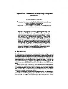
Figure 3: Turbine flowpath calculations 4 RESULTS
Figure 3 shows a typical velocity triangle based calculation that is performed during a 1-D aerodynamic analysis. In this particular application a GE proprietary code is used to perform the 1-D analysis. The 1-D code is wrapped as a service and and whenever it gets published to the network, it is available for service requestors to be able to execute the specific tasks in a particular job. Each service provider is identified by a unique interface and a unique provider name and the service requestor can select individual service providers based on these attributes. In addition to this, each provider can perform more than one service and depending on the type and number of inputs specified, the provider can intelligently determine the specific service that is requested.
A specific aspect of the Turbine Aerodynamic Preliminary Design process is defined as a job and executed using the FIPER framework. The 1-D aerodynamic code is exposed as a FIPER service. The specific example that is chosen requires evaluating the turbine 1-D performance over 20 different thermodynamic cycle points so that the designer can then narrow down the design space to a region that maximizes performance while meeting all the other design constraints. Figure 4 shows the turbine performance map for the 20 thermodynamic cycle points. The Case IDs are plotted on the X-axis and the performance parameter is plotted along the Yaxis. Actual names of performance parameters have been substituted by numbers to protect the proprietary information at General Electric.
118
Figure 4: Turbine performance map very time consuming process. The strength of a distributed environment lies in the ability to perform such operations in a parallel environment. The 20 analyses were defined as 20 individual jobs and were spawned to different number of service providers and data was collected on the time it takes for all 20 jobs to complete.
To obtain these results, the 1-D analysis code has to be executed 20 times and the output from the analysis has to be post-processed to extract the necessary performance parameter. For a typical turbine design, hundreds of such analyses are executed in order to accurately map the entire design. The process is typically performed sequentially, resulting in a
Figure 5: Execution time for different number of service providers service provider. One can observe the liner trend in the execution time going from 1 to 20 providers. There is an almost 90% reduction in the time it takes to execute 20 jobs using a single service provider as compared to using 20 service providers. The minor variation from a strictly linear trend is due to the network traffic at the time of execution and due to network latency during the process of provider lookup and discovery.
Figure 5 shows the data collected when the 20 jobs are all run on 1, 5, 10, 15 and 20 service providers. The actual execution time is plotted as red-colored points and a trend line is also plotted to indicate the trend. In the case where more than one job is sent to a particular service provider, the first job has to execute first before the next job can be executed. The execution time for the different cases is normalized with the execution time for the case with one 1-D 119
12. H. Casanova and J. Dongarra, NetSolve: A networkenabled server for solving computational science problems, The International Journal of Supercomputer Applications and High Performance Computing, 11(3) (1997) 212-223. 13. W. Johnston, D. Gannon, and B. Nitzberg, Grids as production computing environments: The engineering aspects of NASA’s information power grid, Proc. Eighth IEEE International Symposium on High Performance Distributed Computing, (1999). 14. D. Ingram, Soft Real Time Scheduling for General Purpose Client-Server Systems, Proc. of the 7th Workshop on Hot Topics in Operating Systems, (1999). 15. K. Aida, A. Takefusa, H. Nakada,S. Matsuoka, S. Sekiguchi and U. Nagashima, Performance evaluation model for scheduling in a global computing system, The International Journal of High Performance Computing Applications, 14, No. 3 (2000). 16. I. Foster and C. Kesselman, Globus: A Metacomputing Infrastructure Toolkit, The International Journal of Supercomputer Applications and High Performance Computing, 11 (2) (1997) 115–128. 17. M.A. Natrajan, Humphrey and A.S. Grimshaw, Grids: Harnessing geographically-separated resources in a multi-organisational context, 15th Annual International Symposium on High Performance Computing Systems and Applications (2001). 18. H. Casanova, Simgrid: A Toolkit for the Simulation of Application Scheduling, Proceedings of the First IEEE/ACM International Symposium on Cluster Computing and the Grid, (Brisbane, Australia, 2001). 19. M. Van Steen, P. Homburg and A. Tanenbaum, Globe: A wide-area distributed system, IEEE Concurrency, 7(1) (1999) 70–78. http://www.cs.vu.nl/˜steen/globe/. 20. Kolonay, R., Sobolewski, M., 2004, Grid Interactive Service-oriented Programming Environment, Concurrent Engineering: The Worldwide Engineering Grid, Tsinghua Press and Springer Verlag, ISBN 7-30208802-0, pp. 97-102. 21. Soorianarayanan, S., Sobolewski, M., 2004, Monitoring Federated Services in CE, Concurrent Engineering: The Worldwide Engineering Grid, Tsinghua Press and Springer Verlag, ISBN 7-302-08802-0, pp. 89-95. 22. Sobolewski M., Soorianarayanan S, Malladi-Venkata R-K., 2003, Service-Oriented File Sharing, Proceedings of the IASTED Intl., Conference on Communications,Internet, and Information technology, pp. 633639, Nov 17-19, 2003, Scottsdale, AZ. 23. Lapinski M., Sobolewski M., 2002, Managing Notifications in a Federated S2S Environment, International Journal of Concurrent Engineering: Research & Applications, Dec 2002. 24. Sobolewski, 2002. Federated P2P Services in CE Environments, Advances in Concurrent Engineering, A.A. Balkema Publishers, 2002, ISBN 90 5809 502 9, pp. 13-22. 25. Zhao, Shuo, and Michael Sobolewski, 2001, Context Model Sharing in the FIPER Environment, Proc. of the 8th Int. Conference on Concurrent Engineering: Research and Applications, Anaheim, CA. 26. Edwards, W.K. (2000). Core Jini, 2nd ed., Pren-tice Hall, ISBN: 0-13-089408. 27. Jini Architecture Specification. Available at URL: http://www.sun.com/jini/specs/jini1_1.pdf. 28. Freeman, E., Hopfer, S., & Arnold, K.(1999), Javaspaces™ Principles, Patterns, and Practice, AddisonWesley, ISBN: 0-201-30955-6
5 CONCLUSIONS Use of a distributed service based environment reduces the throughput of the design process via parallel execution of analyses over the network. The process scales almost linearly as more and more services are added to the network. Since the architecture uses a dynamic service discovery mechanism allowing new services to enter the network and disabled services to leave the network with need for reconfiguration. This allows the process to be distributed without sacrificing the robustness of the process. This architecture also improves the utilization of the network resources by distributing the execution load over multiple nodes of the network. 6 REFERENCES 1.
Federated Intelligent Product EnviRonment, Technical Proposal, Ohio Aerospace Institute, General Electric Company, BFGoodrich, Parker Hannifin, Engineous Software, Ohio University, April 1999. 2. Engineous Software Incorporated, http://www.engineous.com/index.htm 3. S. Goel, D. Cherry and B. Gregory, Knowledge-Based System for Preliminary Aerodynamic Design of Aircraft Engine Turbines, Applications of Artificial Intelligence XI: Knowledge-Based Systems in Aerospace and Industry, (Orlando, Florida, April 1993). 4. S. Goel, J.I. Cofer and H. Singh, Turbine Airfoil Design Optimization, International Gas Turbine and Aeroengine Congress and Exposition, (Birmingham, UK, June 10-13, 1996). 5. M.A. Kolb and M.W. Bailey, FRODO: ConstraintBased Object-Modeling for Preliminary Design, Advances in Design Automation, (1993) 307-318. 6. A. Takefusa, S. Matsuoka, H. Ogawa, H. Nakada, H. Takagi, M. Sato, S. Sekiguchi and U. Nagashima, Multi-client Performance Analysis of HighPerformance Global Computing, Proceedings of the 1997 ACM/IEEE Supercomputing Conference (1997). 7. David P. Anderson, Jeff Cobb, Eric Korpela, Matt Lebofsky, Dan Werthimer, SETI@home: An Experiment in Public-Resource Computing, (Space Sciences Laboratory, U.C. Berkeley, 2002). 8. T. DeFanti, I. Foster, M. Papka, R. Stevens and T. Kuhfuss, Overview of the I-Way: Wide area visual supercomputing, International Journal of Supercomputing Applications and High Performance Computing, 10 (2) (1996) 123–131. 9. A. Takefusa, S. Matsuoka, H. Ogawa, H. Nakada, H. Takagi, M. Sato, S. Sekiguchi and U. Nagashima, Multi-client Performance Analysis of HighPerformance Global Computing, Proceedings of the 1997 ACM/IEEE Supercomputing Conference (1997). 10. S.S. Tong, D.J. Powell, and S. Goel, Integration of Artificial Intelligence and Numerical Optimization Techniques for the Design of Complex Aerospace Systems, 1992 Aerospace Design Conference, (Irvine, CA, February 1992), AIAA-92-1189. 11. S. Vadhiyar and J. Dongarra, GrADSolve - A Gridbased RPC system for Remote Invocation of Parallel Software, Journal of Parallel and Distributed Computing, (2003). 120