Available online at www.sciencedirect.com
ScienceDirect Procedia Engineering 102 (2015) 1555 – 1562
The 7th World Congress on Particle Technology (WCPT7)
Preparation and characterization of core-shell structure Fe3O4@C magnetic nanoparticles Da Shi, Hao Yang, Shengfu Ji*, Sai Jiang, Xuefei Liu, Danni Zhang State Key Laboratory of Chemical Resource Engineering, Beijing University of Chemical Technology, 15 Beisanhuan Dong Road, Beijing 100029, PR China
Abstract The core-shell structure Fe3O4@C magnetic nanoparticles were synthesized with superparamagnetic Fe3O4 nanosphere as a magnetic core, glucose, phenolic and soluble starch resin as carbon source via a solvothermal method. The structure of Fe 3O4@C magnetic nanoparticles was characterizes using TEM, XRD and VSM. The effects of preparation conditions in the structure of the Fe3O4@C magnetic nanoparticles were taken out. The results indicate: Fe3O4@Cg magnetic nano particle with glucose as carbon source has 250 nm diameter and 8-10 nm thickness of carbon shell; Fe3O4@Cp has 160 nm diameter and 6-8 nm carbon shell with phenolic as carbon source; when the carbon source changes to soluble starch, the magnetic nano particle prepared with 150 nm diameter and 15-20 nm carbon shell. Through XRD, the magnetic nano particles Fe3O4@C synthesized with three kinds of carbon sources have amorphous carbon diffraction peak except for all the characteristic peaks of Fe3O4. The magnetism of Fe3O4@Cg, Fe3O4@Cp and Fe3O4@Cs are 74.1 emu/g, 48.7 emu/g and 41.3 emu/g, respectively. © 2015 Published by Elsevier Ltd. This is an open access article under the CC BY-NC-ND license © 2014The TheAuthors. Authors. Published by Elsevier Ltd. (http://creativecommons.org/licenses/by-nc-nd/4.0/). Selection and peer-review under responsibility of Chinese Society of Particuology, Institute of Process Engineering, Chinese Selection and under responsibility of Chinese Society of Particuology, Institute of Process Engineering, Chinese Academy Academy ofpeer-review Sciences (CAS). of Sciences (CAS)
Keywords: Core-shell; Fe3O4; Fe3O4@C; Magnetic; Nanoparticle
1. Introduction With mature preparative technique of Fe3O4 magnetic nano particles, it has been widely used into magnetic fluid, magnetic record materials, stealth materials, bioseparation, printing and dyeing, catalyst [1-3]. Just a few years, there
* Corresponding author. Tel.: +86-10-64419619; fax: +86-10-64419619. E-mail address:
[email protected]
1877-7058 © 2015 The Authors. Published by Elsevier Ltd. This is an open access article under the CC BY-NC-ND license
(http://creativecommons.org/licenses/by-nc-nd/4.0/). Selection and peer-review under responsibility of Chinese Society of Particuology, Institute of Process Engineering, Chinese Academy of Sciences (CAS)
doi:10.1016/j.proeng.2015.01.291
1556
Da Shi et al. / Procedia Engineering 102 (2015) 1555 – 1562
are lots of reports about new materials related to the application of nano Fe 3O4 into surface modification and catalyst modification. The modifications are focus on two fields of magnetic sphere particles, one is covering porous SiO 2, Al2O3, active carbon and TiO2 on Fe3O4 [4-7] and the other one is loading active components such as nano metal with special catalysis or metallic oxide on them [8,9]. The magnetic nano particles with carbon shell have good surface chemistry characteristics with larger Surface area and pore volume, which can load active components better to show preferable characters on catalytic reactions compared with common ones. Currently, magnetic carbon nano catalysts always synthesis with saccharides such as: glucose, starch and so on or poly furfural as carbon resource [10-12]. Li [13] prepared hollow aluminium acid salt particles at first and added iron nitrate to synthesis magnetic core through roasting. Then taking furfural as carbon source, they carbonized the material to slough template to get HMCSMC which had large BET with 617 m2/g and had good result as adsorption to bilirubin. Zhu [14] and Chen [15] used glucose as carbon resource respectively to synthesized magnetic core-shell nano particles with carbon shell. However, the process of coating glucose is a hydrolytic process, which wasted much glucose during the process. At the same time, the hydrolytic process would corrode Fe3O4 by producing acid and the proportion of reactants and reaction time would influence the preparation of carbon sphere to effect the performance of catalyst. This paper synthesized Fe3O4 particles via a solvothermal method and used glucose, phenolic and soluble starch resin as carbon source to prepare carbon shell through roasting. At last, we got magnetic nano core-shell structure: Fe3O4@Cg, Fe3O4@Cp and Fe3O4@Cs, respectively. And we investigated the effect of the proportion of reactants and reaction time on the structure of Fe3O4@C. Then we used TEM to observe the morphology of Fe3O4@C, XRD to characterize the structure of Fe3O4@C and VSM to characterize the magnetism of Fe3O4@C. 2. Experimental Section 2.1. Synthesis of Fe3O4 Magnetic Fe3O4 nanoparticles were prepared by solvothermal method following the method reported [16]. 4.32 g of FeCl3·6H2O, 12.0 g of sodium acetate and 12 g polyvinylpyrrolidone-K30(PVP-K30) were dissolved in 160 mL of glycol under stirring. The obtained homogeneous yellow solution was transferred to a 200 mL Teflon-lined stainless-steel autoclave. The autoclave was sealed and heated at 200 oC. After heated for 12 h, the autoclave was naturally cooled to room temperature. The obtained black magnetite particles were separated with a permanent magnet, washed with deionized water and ethanol, and dried in vacuum at 60 oC for 24 h. 2.2. Synthesis of Fe3O4@C 2.2.1. Synthesis of Fe3O4@Cg According to the reference [12], 0.1 g of Fe3O4 nanoparticles, 2 g of glucose and 1g PVP-K30 were dissolved in 80 ml deionized water under ultrasound for 30 mins. The obtained solution was transferred to a 100 mL Teflon-lined stainless-steel autoclave. The autoclave was sealed and heated at 180 oC for 12 h. When the autoclave was naturally cooled to room temperature, the products were washed with deionized water and ethanol and dried in vacuum at 60 o C for 6 h to get Fe3O4@Cg. 2.2.2. Synthesis of Fe3O4@Cp According to the reference [14], preparing for phenolic resin, 12.2 g of phenol melted in three-necked flask under 40-42 oC and moved 2.1 ml of 20% NaOH solution into flask under stirring. After 10mins, added 21.4 ml of 37% formaldehyde solution under 50 oC. Then increased the temperature to 72 oC and stirred for 1 h. The solution was naturally cooled to room temperature and neutralized to pH=7. Then used rotary evaporators to dry the solution and got red solution for standby application. 0.1 g of Fe3O4 nanoparticles, 0.06 g of phenolic resin and 1g PVP-K30 were dissolved in 20 ml deionized water under ultrasound for 30 mins. Then transferred the solution to three-necked flask and added 60 ml deionized water
Da Shi et al. / Procedia Engineering 102 (2015) 1555 – 1562
1557
under stirring for 12 h at 25 oC. The obtained solution was transferred to a 100 mL Teflon-lined stainless-steel autoclave. The autoclave was sealed and heated at 180 oC for 12 h. When the autoclave was naturally cooled to room temperature, the products were washed with deionized water and ethanol and roasted under nitrogen protection with a temperature programme (20 oC increased to 350 oC during 60 mins, then increased to 450 oC during 100 mins and contained 4 h) to get Fe3O4@Cp. 2.2.3. Synthesis of Fe3O4@Cs According to the reference [17], 0.2 g of Fe3O4 nanoparticles, 5 g of starch and 2 g PVP-K30 were dissolved in 80 ml deionized water under stirring for 30 mins. The obtained solution was transferred to a 100 mL Teflon-lined stainless-steel autoclave. The autoclave was sealed and heated at 180 oC for 9 h. When the autoclave was naturally cooled to room temperature, the products were washed with deionized water and ethanol and dried in vacuum at 60 o C for 12 h to get Fe3O4@Cs. 2.3. Characterization Transmission electron microscopy (TEM) was performed with a JEOL (JEM-2100) transmission electron microscope (JEOL, Japan) operated at 200 kV accelerating voltage. The X-ray diffraction (XRD) pattern was collected on a D/Max 2500 VB 2+/PC diffractometer (Rigaku, Japan) with Cu –Kα irradiation (λ = 1.5418 Å, 200 kV, 50 mA) in the range of 2θ value between 10° and 80°. Magnetic properties of the samples were measured using a vibrating sample magnetometer (VSM; Lake Shore Model 7400, USA) under magnetic fields up to 20 kOe. 3. Results and Discussion 3.1. TEM of Fe3O4@C
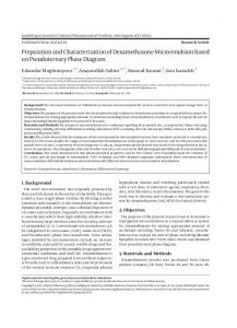
Fig.1. TEM images of samples: (a) Fe3O4; (b) Fe3O4@Cg; (c) Fe3O4@Cp; (d) Fe3O4@Cs.
1558
Da Shi et al. / Procedia Engineering 102 (2015) 1555 – 1562
The TEM images of superparamagnetic Fe3O4 nano spheres and Fe3O4@C magnetic nanoparticles with different kinds of carbon resource are shown in Fig. 1. For superparamagnetic Fe3O4 nano spheres, the diameters are between 100 and 200 nm (Fig.1-a). When the reaction time is 12 h, Fe3O4@Cg (glucose as carbon resource) magnetic nanoparticles have nearly 250 nm diameters and 8-10 nm carbon shell (Fig.1-b); Fe3O4@Cp (phenolic resin as carbon resource) magnetic nanoparticles have nearly 160 nm diameters and 6-9 nm carbon shell (Fig.1-c); Fe3O4@Cs (starch as carbon resource) magnetic nanoparticles have nearly 150 nm diameters and 15-20 nm carbon shell (Fig.1-d). The results show that magnetic nanoparticles Fe3O4@C with different carbon resources have differences about the diameters of magnetic nanoparticles and their thickness of carbon shell. During the process of synthesizing carbon shell, because of the structure of carbon resources the differences between states of aggregation of micromolecules contribute to the different thickness of carbon shell. 3.1.1. Effect of time to Fe3O4@C The TEM images of the change of Fe3O4@Cg with different reaction time are shown in Fig.2. For 3 h, Fe3O4 is on a status between uncoated and coated (Fig.2-a). When the time lasts for 12 h, Fe3O4@Cg particles have obvious core-shell structure (Fig.2-b) and an integument with the thickness of 8-10 nm. With the reaction time increasing, the thickness of carbon shell increases (Fig.2-c), but they also produce big carbon spheres due to auto-agglutination of glucose for the long time. Hence, using glucose as carbon resource to coat Fe3O4 nanoparticles can control the thickness of carbon shell and get thicker shell compared with reference [10] through the control of reaction time. The TEM images of the change of Fe3O4@Cp with different reaction time are shown in Fig.3. For Fe3O4@Cp, they have the similar trend about the relationship between thickness of carbon shell and reaction time. When the reaction time is 12 h (Fig.3-b), Fe3O4@Cp particles have uniform carbon shell with the thickness of 6-8 nm on the surface of Fe3O4. With the reaction time increasing, the thickness of carbon shell does not have obvious changes. The thinner thickness may because of lager intermolecular forces between phenolic resin and surface of Fe3O4. The TEM images of the change of Fe3O4@Cs with different reaction time are shown in Fig.4. From the TEM images, amorphous carbon changes from anomalous thick shell to uniform thickness of carbon shell. For 3h (Fig.4a), the carbon shell coats on local places of Fe3O4 spheres surface; for 6 h (Fig.4-b), the nanoparticles have the whole core-shell structure, but the thickness of carbon shell is only 5-10 nm. With the reaction time growing, the thickness of carbon shell is increasing from half-coated to whole-coated. At last, the surface is more and more smooth. After 12 h, the carbon shell is 15-20 nm (Fig.4-c) and it does not have obvious changes with longer time. When choose stretch as carbon source, its structure is more complex than glucose with longer chain. Considering the carbon amount in polysaccharide is more, the thickness of carbon shell is thicker.
Fig.2. TEM images of Fe3O4@Cg with reaction time (a)3 h; (b)12 h; (c)24 h.
Da Shi et al. / Procedia Engineering 102 (2015) 1555 – 1562
Fig.3. TEM images of Fe3O4@Cp with reaction time (a)6 h; (b)12 h; (c)24 h.
Fig.4. TEM images of Fe3O4@Cs with reaction time (a)3 h; (b)6 h; (c)12 h.
3.1.2. Effect of material proportion’s to Fe3O4@C
Fig.5. TEM images of Fe3O4@Cp with reactants proportion (a)1:0.7; (b)1:1.4; (c)1:2.1 (reaction time 12 h).
1559
1560
Da Shi et al. / Procedia Engineering 102 (2015) 1555 – 1562
Fig.6. TEM images of Fe3O4@Cp with reactants quality (a)2.5 g; (b)5 g; (c)10 g (reaction time 12 h).
The TEM images of the change of Fe3O4@Cp with different reactants mole proportions between Fe3O4 and phenolic resin are shown in Fig.5. When the proportion is 1:0.7, phenolic resin synthesizes a thick shell on Fe 3O4 surface with 3.5 nm (Fig.5-a). For 1:1.4, the thickness of carbon shell increases to 6.7 nm (Fig.5-b). When the mole ratio rises to 1:2.1, the thickness grows to 9.6 nm (Fig.5-c). With growing mole proportion, the thickness does not have obvious changes. Hence, it will easily to change coated thickness from3.5 nm to 9.6 nm through changing the proportion of phenolic resin. At the same time, the core-shell structure can protect Fe3O4 form oxidation and acid environment so that the catalysts can contain better magnetic and reusable properties. The TEM images of the change of Fe3O4@Cs with different reactants quality between Fe3O4 and starch are shown in Fig.6. From TEM images, the nanoparticles have uniform diameter and all Fe3O4@Cs particles have coreshell structure with different quality of starch. But when the amount of starch is few, the Fe3O4@Cs’ core-shell structure is not obvious. There is only a thin and nonuniform carbon shell (Fig.6-a). With increasing amount of starch, the core-shell structure is more obvious and the thickness of carbon shell increases obviously with smoother surface (Fig.6-b). However, the thickness does not change during the growing amount of starch (Fig.6-c). 3.2. XRD of Fe3O4@C
Intensity(a.u)
Fe3O4
d c b a 20
40
60
80
2 Theta(degree)
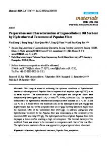
Fig.7. XRD patterns of samples: (a)Fe3O4; (b) Fe3O4@Cs; (c) Fe3O4@Cg; (d) Fe3O4@Cp.
1561
Da Shi et al. / Procedia Engineering 102 (2015) 1555 – 1562
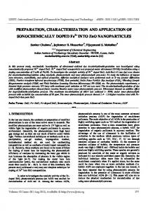
The XRD patterns of superparamagnetic Fe3O4 nano spheres and Fe3O4@C magnetic nanoparticles with different kinds of carbon resource are shown in Fig.7. From the figure, the Fe3O4@C with different carbon resources has similar patterns with Fe3O4 and all the characteristic peaks of Fe3O4 which are identical with standard Fe3O4 XRD pattern are kept, which means the crystalline form of Fe3O4 does not change during the hydrothermal process. At the same time, the core-shell structure Fe3O4@C magnetic nanoparticles with different carbon resources have obvious diffuse characteristic peaks at 2θ=15-25 o which belong to amorphous carbon [17]. Besides, the thicknesses of carbon shell affect the intensity of the characteristic peaks of Fe3O4. On one hand, the increase of carbon shell thickness can decrease the relative quality of Fe3O4, so the thinner thickness of carbon shell when use phenolic resin as carbon resource leads to weaker intensity of diffuse characteristic peaks of carbon; on the other hand, with the growing amount of reactants concentration, the reactions will produce excessive amounts of organic acids (pH=3-4 during experiments), which will eat off parts of Fe3O4 and leads to the fall of the relative amount of Fe 3O4. Hence, taking starch as carbon resource to prepare Fe3O4@C has the strongest intensity of diffuse characteristic peaks of carbon. 3.3. VSM of Fe3O4@C The magnetization curves of superparamagnetic Fe3O4 nano spheres and Fe3O4@C magnetic nanoparticles with different kinds of carbon resource are shown in Fig.8. All curves appear nonlinear and reversible characteristic with no hysteresis (zero coercivity and no remanence), exhibiting superparamagnetic behaviour. The saturation magnetization (Ms) value of Fe3O4 is 86.3 emu/g. Although the magnetism is weak after coating carbon shell, the saturation magnetization values of Fe3O4@Cp, Fe3O4@Cg and Fe3O4@Cs are 74.1 emu/g, 48.7 emu/g and 41.3 emu/g respectively, which can completely meet the requirement of the magnetic separation and protect Fe3O4@C from agglomeration to guarantee better dispersibility at the same time. Different carbon resources contribute to the differences between magnetism due to the thickness of carbon shell (from TEM results). The increasing amount of carbon decreases the relative quality of Fe3O4, which leads to the reduction of the intensity of saturation magnetization values. 100 80
a b c d
Magnetization(emu/g)
60 40 20 0 -20 -40 -60 -80 -100 -20000
-15000
-10000
-5000
0
5000
10000
15000
20000
Applied magnetic field(Oe)
Fig.8. Magnetization curves of samples: (a)Fe3O4; (b) Fe3O4@Cp; (c) Fe3O4@Cg; (d) Fe3O4@Cs.
1562
Da Shi et al. / Procedia Engineering 102 (2015) 1555 – 1562
4. Conclusion Fe3O4@C magnetic nanoparticles with 100-200 nm diameters and 8-20 nm carbon shell were synthesized with superparamagnetic Fe3O4 nanosphere as a magnetic core, glucose, phenolic and soluble starch resin as carbon source. And through the research about preparation conditions, the thickness of carbon shell can be controlled through reaction time and reactants proportions. Through characterization methods, the results show that the intensity of diffuse characteristic peaks of amorphous carbon will increase with the growing carbon thicknesses. On the opposite, the magnetization values will decrease, but this will not affect the magnetic separation. Because of the stability of carbon shell, the Fe3O4 magnetic core is protected and its strengths about easily recycling and controlled thickness makes it has better application in the future. Acknowledgements Financial funds from the National Natural Science Foundation of China (Grant No. 21173018 and 21136001) are gratefully acknowledged. References [1] A. Ito, M. Shinkai, H. Honda, Medical application of functionalized magnetic nanoparticles, J. Biosci. Bioeng. 100 (2005) 1-11. [2] Y. Yong, Y. Bai, Y. Li, Preparation and application of polymer-grafted magnetic nanoparticles for lipase immobilization, J. Magn. Magn. Mater. 320 (2008) 2350-2355. [3] H. Gu, K. Xu, C. Xu, Biofunctional magnetic nanoparticles for protein separation and pathogen detection, Chem. Commun. 9 (2006) 941-949. [4] V. Polshettiwar, R. Luque, A. Fihri, H.B. Zhu, M. Bouhrara, J. M. Basset, Magnetically Recoverable Nanocatalysts, Chem. Rev. 111 (2011) 3036-3075. [5] M. Bowker, J.D. Ames, P. Stone, R. Bennett, N. Perkins, L. Millard, J. Greaves, A. Dickinson, Catalysis at the metal-support interface: exemplified by the photocatalytic reforming of methanol on Pd/TiO2, J. Catal. 217 (2003) 427-433. [6] P. Liu, L. Wang, Y.Z. Liu, Chitosan-immobilized Palladium Complex: a Green and Highly Active Heterogeneous Catalyst for Heck Reaction , Chin. J. Chem. 15 (2004) 475-477. [7] R.T. Tao, Z.Y. Sun, Y. Xie, H.Y. Zhang, C.L. Huang, Y.F. Zhao, Z.M. Liu, In situ loading of palladium nanoparticles on mica and their catalytic applications, J. Colloid. Interf. Sci. 353 (2011) 269-274. [8] B. Lev, P.C. Emily, T.A. Hatton, C. Angel, M. Beatriz, A.L. Carmen, Bactericidal Core-Shell Paramagnetic Nanoparticles Functionalized with Poly(hexamethylene biguanide), Langmuir 27 (2011) 420-429. [9] H.P. Peng, R.P. Liang, J.D. Qiu, Facile synthesis of Fe3O4@Al2O3 core-shell nanoparticles and their application to the highly specific capture of heme proteins for direct electrochemistry, Biosens Bioelectron 26 (2011) 3005-3011. [10] L. Kong, X. Lu, X. Bian, Constructing Carbon-Coated Fe3O4 Microspheres as Antiacid and Magnetic Support for Palladium Nanoparticles for Catalytic Applications, ACS Appl. Mater. 3 (2010) 35-42. [11] Y. Meng, D. Gu, F. Zhang, A family of highly ordered mesoporous polymer resin and carbon structures from organic-organic self-assembly, Chem. Mat. 18 (2006) 4447-4464. [12] F. Zhang, Y. Meng, D. Gu, A facile aqueous route to synthesize highly ordered mesoporous polymers and carbon frameworks with Ia3d bicontinuous cubic structure, J. Am. Chem. Soc. 127 (2005) 13508-13509. [13] L. Guo, C. X ui, Y. Li, Hollow mesoporous carbon spheres with magnetic cores and their performance as separable bilirubin adsorbents, Chem-Asian J. 4 (2009) 1480-1485. [14] Y. Zhu, L.P. Stubbs, F. Ho, Magnetic nanocomposites: a new perspective in catalysis, Chem. Cat. Chem. 2 (2010) 365-374. [15] Y.J. Chen, G. Xiao, T.S. Wang, Q.Y. Ouyang, L.H. Qi, Y. Ma, P. Gao, C.L. Zhu, M.S. Cao, H.B. Jin, Porous Fe3O4/carbon core/shell nanorods: synthesis and electromagnetic properties, J. Phys. Chem. C 115 (2011) 13603-13608. [16] H.F. Liu, S.F. Ji, H. Yang, H. Zhang, M. Tang, Ultrasonic-assisted ultra-rapid synthesis of monodisperse meso-SiO2@Fe3O4 microspheres with enhanced mesoporous structure, Ultrason. Sonochem. 21 (2014) 505-512. [17] J.S. Qiu, Y.F. Sun, Y. Zhou, T.J. Sun, Q.X. Li, Preparation and magnetic properties of carbon encapsulated iron nanocapsules from starch, New Carbon Mater. 21 (2006) 202-205.