International Renewable Energy Congress November 5-7, 2010 – Sousse, Tunisia
Modelling and control of MicroGrids in Island Operation J. Salazar(a), F. Tadeo(b), C. de Prada(c), L. Palacin(d) (a) (b) (c)
(a)
Dpt of System Engineering and automatic control, Faculty of Science, University of Valladolid, Spain (d) Sugar Technology Center (CTA), Valladolid, Spain
[email protected], (b)
[email protected], (c)
[email protected], (d)
[email protected]
ABSTRACT
A microgrid is a low voltage (LV) network plus its loads, several small generation units connected to it, providing power to local loads. Microgrid can operate in gridconnected mode and island mode. Grid-connected mode occurs when microgrid is connected to main grid or diesel generator. Island mode occurs when microgrid is disconnected from main grid or diesel generator, it operates as a separate island where microsources and storage device should co-operate with each other to maintain the integrity of the islanded microgrid. This paper presents dynamic models and a control strategy in island mode. These dynamic models can be used for dynamic simulation in order to test different configurations, as well as control strategies and fault detection and accommodation algorithms. Keywords – Microgrid, Island operation, PQ control, VSI Control, Voltage and Frequency droop control.
I.
INTRODUCTION
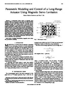
A MicroGrid (MG) is a low voltage (LV) network plus its loads, several small generation units connected to it, providing power to local loads [1]. Thus, the operational architecture presented in Figure 1, comprises an LV network, a load, microsources, a storage device and a hierarchical type management and control scheme supported by a communication infrastructure used to monitor and control microsources and loads. Microgrid can operate in grid connected mode and island mode. Both modes will be present as follows [2].
Grid-connected Mode: Microgrid is connected to main grid or diesel generator, either being supplied by it or injecting some amount of power into the main grid, depending on generation.
ID178/ ©IREC2010
Island Mode: Microgrid is disconnected from main grid or diesel generator and operates as a separate island
Batteries
DC
PV
DC AC
Turbine
DC AC
AC
LV
MV
MC
MC
MC
LC
MGCC Load
Figure 1.- MicroGrid Control Architecture [3]
A Microgrid comprises also an hierarchical control and management system: in an upper level, the MiocroGrid Central Controller (MGCC) provides the technical and economical management of the Microgrid; in a lower level, Load Controllers (LC) can be used for load control, making use of an interruptibility concept; also MicroSource Controllers (MC) are used to locally control the active and reactive power production levels. MicroSources (MS) are small units of less than 100 kWe, most of them with power electronic interface (DC/AC or AC/DC/AC), using either renewable energy sources (wind and solar energy) or fossil fuel in high efficiency local co-generation mode (microturbines or fuel cells). This power electronic interface refers to grid side converter.
This paper is concerned with modeling and control strategy on grid side converter in island mode. The rest of paper is organized as follows: Section 2 focuses on modelling of grid side converter, which is used for connecting microsource to network. In section 3, The structure and feature of proposed control strategy is presented. Section 4 introduces a voltage 388
and frequency droop control method and Section 5 describes battery inverter model.
1 and vice verse. As we have two variables, there are (22=4) possible switching vectors (see Table I). Idc
II.
GRID SIDE CONVERTER MODELING Q1
Basically each microsource unit may have DC or rectified generation unit, storage devices, DC-DC converter, DC-AC inverter, AC filter, and transformer for connecting to loads or main grid in order to exchange power [4-7]. For simplification it is considered that DC side is a constant DC source. This paper is focus on modelling and control of DC-AC inverter. A circuit model of a single-phase DC-AC inverter with LCL output filter is described in Figure 2. The system consists of a microsource, an output filter and a low frequency transformer which provides a galvanic isolation between the microsource and grid.
Udc
AC Filter
Udc
Q4
Figure 3.- Structure of the single phase voltage source converter
The applied voltages at the AC filter terminals as a function of the DC-link voltage. The switching functions is: Q1 1 0 1 0
1 2 3 4
Grid
Ic C
Uinv
Q2
Grid Side Converter
Idc MicroSource
Iinv
Udc
State DC - Link
Q3
Transformer
Q3 0 1 1 0
Uinv Udc -Udc 0 0
DC/AC
Figure 2.- Circuit of the Microsource Inverter
a.
DC-Link Model
The DC link model is based on the principle of conservation of energy. Thus, the difference between the instantaneous power from the microsource or cuk converter and the one taken by the network side converter is equal to the variation of the energy stored in the capacitor time. In this paper we do not consider the losses of the converters. U dc (1) Ic C I dc I inv t Where, C is capacitor, Ic is capacitor current, Idc is output current of microsource or cuk converter.
Due to the fact that the inverter is assumed lossless and constructed without storage energy components, the instantaneous power balance indicates that: (2) U dc I dc U inv I inv Considering that output AC current Iinv is taken from AC Filter, output voltage Uinv is considered sinusoidal and DC link voltage remains constant Udc, The DC link current Idc is given by: U I (3) I dc inv inv U dc Several modulating techniques applicable to full-bridge VSIs have been developed. Among them are the PWM (bipolar and unipolar) techniques. c.
b.
Grid Side Converter Model
The Voltage Source Converter (VSC) converter can operate in rectifier or inverter mode, thus a bi-directional power flow can be achieved. In this paper, the grid side converter works as an inverter [8]. A VSC can be implemented in several ways: six-step, Pulse Amplitude Modulated (PAM) or Pulse Width Modulated (PWM). The paper is focused on the implementation of a PWM VSC, but the idea can be easily extended to other configurations. A single-phase inverter is shown in Figure 3; where Udc is the voltages of the dc bus capacitors; Uac is the phase voltage and each switch is identified with the letter Q. It is assumed that Q1 and Q2 as well as Q3 and Q4 are switched in a complementary way to avoid a short circuit in the voltage source. Thus, the analysis of the switches turn-ons/offs is simplified. We only consider the two upper transistors Q1 and Q3. If the switch of the transistors Q1 is on, then Q1 is equal to ID178/ ©IREC2010
AC Filter Model
The line filter reduces the high frequency harmonic content of the line current caused by the switched operation of the VSI. The line filter consists of filter inductors with other combinations of capacitors and inductors such as LC or LCL filters. The L-filter is a first-order filter. Its attenuation is 20 dB/decade over the whole range of frequency. Using this filter, the switching frequency of the converter has to be high to obtain sufficient attenuation of the harmonics caused by the PWM converter. The LCL filter (Figure 4) is a third-order filter. Its attenuation is 60 dB/decade for frequencies over the resonance frequency. it is possible of using a relatively low switching frequency [9]. Iinv
Uinv
L1
L2
Uf
Cf
Ig
Ug
389
Figure 4.- LCL Filter Single Phase Case
The mathematical model of the LCL-filter is given by: I inv U f t I g U f L2 Ug t U f C I inv I g t
U inv L1
(5) (6)
U ref U o St 2 (Q Qo )
where St1 and St2 are the droop slopes (positive quantities), fo and Uo are nominal frequency and nominal grid voltage respectively, and Po and Qo are the (momentary) setpoints for active and reactive power of the inverter, (see Figure 6)
CONTROL STRATEGIES IN INVERTERS
fo Ug
P
Two kinds of control strategies may be used to operate an inverter: Ig
The PQ controlled inverter operates by injecting into the grid the power available at its input. The reactive power injected corresponds to a pre-specified value. In order to operate with a unit power factor, the pre-specified value Qref is normally set to zero (see Figure 5). Grid Side Converter
DC - Link Ic C
Grid
Idc Udc
AC Filter
Udc
Transformer Pref
DC/AC
f
S’t1
φ
Uref
Q
DC - Link
u,i
Udc
ireact
iref 1 S 1
PI-2
Method Engler Q
Qref
X
Grid Side Converter
Idc
u*=u+k(iref - i)
PI-1
|Uref|
The VSI terminal voltage and current are measured in order to compute active and reactive powers. This measuring stage introduces a delay for decoupling purpose. The output voltages are the reference signals that control the Grid Side Converter switching sequence using a PWM modulation technique (see Figure 7).
MicroSource
X
St2
Figure 6.- Reference Voltage for VSI control
PWM
Udcref
St1
uo
PQ Inverter Control
Micro Source
(8)
Ic C
Grid
III.
(4)
The VSI acts as a voltage source, with the magnitude and frequency of the output voltage controlled through droops method, as described in the following equations: f f o St1 ( P Po ) (7)
AC Filter
Udc
Transformer DC/AC
Current Control Iinv
iact
Uinv
Figure 5.- PQ Inverter Control Voltage Control
The PQ inverter control is implemented as a current controlled voltage source. The components of the current in phase (iact) and quadrature (ireact) with the inverter terminal voltage are computed based on Engler Method which is presented in [10]. Power variations in the microsource induce dc-link voltage errors, which are corrected via the PI-1 regulator, by adjusting the magnitude of the active current delivered to the grid. The reactive power is controlled via the PI-2 regulator by adjusting the magnitude of the output reactive current. VSI Control The VSI can be coupled to storage devices (batteries or flywheels) or to microsource with storage devices in the dclink (batteries, super capacitors), which are charged by the primary energy source.
ID178/ ©IREC2010
Uref
Ug,Ig Droops
Figure 7.- VSI Inverter Control
If microgrid is connected to main power supply or diesel generator, all the inverters can be operated in PQ mode, because there are voltage and frequency reference. If microgrid is disconnected from main grid o diesel generator, it is possible to operate microgrid in island mode, by using a VSI to provide a reference for voltage and frequency. In this case, two main control strategies are possible: a) single master operation (SMO) or b) multi master operation (MMO). a.- Single Master Operation (SMO): a VSI can be used as voltage reference and the other inverters operate in PQ mode (slaves) as shown in Figure 8.
390
Figure 8.- Control scheme for Single Master Operation. [11]
b.- Multi Master Operation (MMO): Several inverters are operating as VSI with pre defined frequency/active power and voltage/reactive power characteristics. Eventually, other PQcontrolled inverters may also coexist (see Figure 9).
low voltage grid reaches an active power supply of the nominal active power PN. In case that the reactive power supply rises, the voltage is reduced starting from the nominal RMS voltage U0. The slope of this droop is a voltage reduction of 6 % of the nominal RMS voltage when low voltage grid reaches a reactive power supply of the nominal reactive power QN. The main principle of voltage and frequency droop control is to use the active and reactive power exchange between a generator or storage unit and the low voltage grid to control the grid voltage magnitude and frequency. The battery inverter also tries to affect the grid’s frequency according to its battery state. If the available power on the AC bus of the system is higher than the power demanded, all battery inverters will charge their batteries and let the idle frequency slightly rise, analogous to the amount of energy stored in their batteries. The other way around, if the available power is less than the power demanded, the missing amount will be fed into the AC bus by the battery inverter, slightly reducing the AC frequency.
Figure 10.- Frequency-active power droop
Figure 9.- Control scheme forMulti Master Operation. [11]
This paper focus on Single Master Operation (SMO), where battery inverter provides reference for voltage and frequency. IV.
A VOLTAGE AND FREQUENCY DROOP CONTROL Figure 11.- Voltage-reactive power droop
Battery inverters with an adequate control offer the fundamental possibility to form low-voltage grids. In order to be able to utilize all the advantages of “Pure AC coupling” in island mode a new control algorithms for battery inverters so called droop mode control [12]-[15] were developed. In island mode, the battery inverter is able to guarantee stable power system conditions by keeping the set voltage and frequency in order to supply different consumers. High power quality is characterised by a sinusoidal voltage of a certain frequency with low harmonic distortion. It uses a battery as a buffer to balance the fluctuating energy generation by solar or wind energy and the fluctuating energy demand. In droop mode, the battery inverter varies the grid’s frequency f depending on its current active power supply P (Figure 10), and the grid’s voltage U depending on its current reactive power supply Q (Figure 11). In case that the active power supply rises, the frequency is reduced starting from the nominal frequency f0. The slope of this droop is a frequency reduction Δf of -2 % of the nominal frequency or 1 Hz when ID178/ ©IREC2010
The battery inverter supplies a current that is the result of the voltage difference between a reference ac voltage source, generated by droop mode, and the grid voltage across a virtual complex impedance. The reference ac voltage is synchronized with the grid, with a phase shift, depending on the difference between rated f0 and actual grid frequency. The droop mode with a frequency droop and a voltage droop allows to connect several battery inverters in parallel. Therewith, the droop mode enables a simple expandability of supply systems. Additionally, it is possible to distribute the share of load automatically by using different slopes for the droops. V.
BATTERY INVERTER MODEL
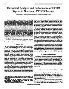
The circuit of the battery inverter is shown in Figure 12. A bidirectional Cuk converter changes the battery voltage, which depends on number of cells. The battery voltage can be 391
between 40 V and 80 V, into a regulated DC-link voltage of 380 V. The HF transformer provides an electric separation between battery and grid. A grid side converter with LCL filter is connected to the DC-link, which generates the sinusoidal voltage for the island grid. The Cuk converter and the grid side converter operate bi-directional, so that the battery inverter can charge and discharge the batteries [16] DC Link
CUK Converter C1
L1
C2
S1
L2
Ic C
S2
AC Filter
Udc
DC/AC
Figure 12.- Circuit of the Battery Inverter
The modelling of cuk converter will be presented throughout this section. A non-isolated Cuk converter is shown in Figure 13, it comprises two inductors, one capacitors, a switch (usually a transistor), and a diode. It is an inverting converter, so the output voltage is negative with respect to the input voltage. The capacitor C is used to transfer energy and is connected alternately to the input and to the output of the converter via the commutation of the transistor and the diode. The two inductors L1 and L2 are used to convert respectively the input voltage source (Ui) and the output voltage source (Uo) into current sources C
L1
Ui
L2 Uo
D
S1
Figure 13.- Schematic of a non-isolated Ćuk converter
Cuk converter has two operating states which will be briefly presented. Off State: Inductor L1 is connected in series with Ui and C as shown in Figure 14, Therefore UL1 = Ui − UC. As the diode D is forward biased (we consider zero voltage drop), L2 is directly connected to Uo. Therefore UL2 = Uo L1
Ui
C
L2 Uo
Figure 14.- Off State of a non-isolated Cuk converter
On State: Inductor L1 is directly connected to the input source. Therefore UL1 = Ui. Inductor L2 is connected in series with C and Uo, so UL2 = Uo − UC. (See Figure 15)
C
L2 Uo
Ui
Figure 15.- On State of a non-isolated Cuk converter
VI.
Grid Side Converter
Grid
Battery
L1
CONCLUSION
This work has presented the dynamic models and a control strategy on grid side converter in island mode. Two kinds of control strategies may be used to operate a grid side converter: PQ inverter Control (the inverter is controlled to inject a given active and reactive power) and VSI control (the inverter acts as a voltage source with controlled magnitude and frequency) . Single master operation was chosen as control strategy in island mode, where battery inverter provides a reference for voltage and frequency. The future work will be to develop a simulation platform suitable for identifying microgrid control requirements and evaluating microgrid dynamic behaviour under several conditions. Ecosimpro environment will be employed in order to get simulation. REFERENCE [1] Robert Lasseter, "Microgrids," IEEE Power Engineering Society Winter Meeting, 2001, vol. 1, pp. 146-149. [2] Robert Lasseter, etal, "White Paper on Integration of Distributed Energy Resources: The CERTS MicroGrid Concept," California Energy Commission, 2002.
[3] J. A. Peças Lopes, C. L. Moreira and A. G. Madureira “Defining Control Strategies for Analysing MicroGrids Islanded Operation,” [4] J. W. Jung, and A. Keyhani, “Modeling and Control of Fuel Cell Based Distributed Generation Systems in a standalone Ac Power System,” Journal of Iranian Association of Electrical and Electronics Engineers, Vol.2, No.1 [5] Kourosh Sedghisigarchi, and Ali Feliachi, “Impact of Fuel Cells on Load-Frequency Control in Power Distribution Systems,” IEEE TRANSACTIONS ON ENERGY CONVERSION, VOL. 21, NO. 1, MARCH 2006 [6] A. M. Daryani, M. Shahini, H.Rastegar, A.A. Ghadimi, “Fuzzy Logic based Fuel Cell output power controller,” 21’th International power system conference (PSC), 2006, Tehran, Iran [7] A.A. Ghadimi, A. M. Daryani, H. Rastegar, “Detailed Modeling and analysis of a full bridge PWM DC-DC converter,” in proceeding of Australasian Universities Power Engineering Conference, AUPEC-2006, Dec 2006, Melbourne, Australia
ID178/ ©IREC2010
392
[8] Cristian Busca, Ana-Irina Stan, Tiberiu Stanciu and Daniel Ioan Stroe. “Control of Permanent Magnet Synchronous Generator for Large Wind Turbines”. IEEE (2008). [9]
Mohan, Undeland, Robbins, “Power Electronics Converter. Application and Design,” third edition, Wiley, 2003
[10] Dr.-Ing. B. Burger, Dipl.-Ing. A. Engler. “Fast Signal Conditioning in Single Phase Systems,” 9th European Conference on Power Electronics and Applications, 27.29.08.2001, Graz B. [11] J. A. Peças Lopes, C. L. Moreira, A. G. Madureira.: “Defining Control Strategies for MicroGrids Islanded Operation,”. IEEE. 2006 [12] A Tuladhar, H. Jin, T. Unger and K. Mauch, “Parallel operation of single inverter modules with no control interconnections,” Proc. IEEE-APEC’97 Conf., Feb 2327, 1997, vol. 1, pp. 94-100 [13] M. C. Chandorkar, D. M. Divan and R. Adapa, “Control of parallel connected inverters en standalone AC supply systems,” IEEE Trans. Ind. Appl., vol. 29, no 1, pp. 136143, Jan-Feb 1993 [14] M. Hauck and H. Späth, “Control of three phase inverter feeding an unbalanced load and operating in parallel with other power source,” in Proc. EPE-PEMC’02 Conf., Sep 9-11, 2002. [15] C.-C. Hua, K-A Liao, and J-R Lin, “Parallel operation of inverters for distributed photovoltaic power supply system,” in Proc. IEEE – PESC’02 Conf, Jun 23-27, 2002, pp. 1979-1983 [16] B. Burger, P. Zacharias, G. Cramer and W. Kleinkauf. “Battery inverter for modularly-structured PV power supply systems” in Proc. IEEE – PESC’03 Conf
ID178/ ©IREC2010
393