International Conference
Nuclear Energy for New Europe 2003 Portorož, Slovenia, September 8-11, 2003 http://www.drustvo-js.si/port2003
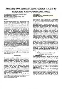
Presentation of Common Cause Failures in Fault Tree Structure of Krško PSA: An Historical Overview Ivan Vrbanić, Ivan Košutić Nuclear Power Plant Krško Vrbina 12, SI-8270 Krško, Slovenia
[email protected],
[email protected] Igor Vuković, Zdenko Šimić Faculty of Electrical Engineering and Computing Unska 3, HR-10000 Zagreb, Croatia
[email protected],
[email protected] ABSTRACT Failure of multiple components due to a common cause represents one of the most important issues in evaluation of system reliability or unavailability. The frequency of such events has relatively low expectancy, when compared to random failures, which affect individual components. However, in many cases the consequence is a direct loss of safety system or mitigative safety function. For this reason, the modeling of a common cause failure (CCF) and its presentation in fault tree structure is of the uttermost importance in probabilistic safety analyses (PSA). During the past decade, PSA model of Krško NPP has undergone many small changes and a couple of major ones in fulfilling its basic purpose, which was serving as a tool for providing an appropriate information on the risk associated with actual plant design and operation. All changes to Krško PSA model were undertaken in order to make it a better tool and / or to make it represent the plant in more accurate manner. The paper provides an overview of changes in CCF modeling in the fault tree structure from the initial PSA model development till present. 1
INTRODUCTION
Common cause failures, a subset of the general class of dependent events, are defined as multiple failures of components from shared root cause. The key characteristic of a common cause event is that two or more components must be affected by a single, shared cause that must not be failure or functional unavailability of another component [1]. CCFs included in plant logic models represent those intercomponent dependencies which are not considered to be potentially significant, and whose mechanisms are not explicitly represented in plant logic model (event tree/fault tree). Specific dependent failure mechanism should be explicitly modeled whenever possible and it is advisable to make a clear distinction between the coverage of such modeling and the scope of CCF analysis [2]. CCFs are an important class of dependent events with respect to their contribution to system unavailability. This is indeed important for redundant and / or diverse systems. Analyses for such systems that only consider coincidental independent failures are likely to grossly underestimate system unavailability and will provide misleading indications of the benefits of redundancy and diversity in system design. 353.1
353.2
During the past decade, PSA model of Krško NPP has undergone many small changes and a couple of major ones in fulfilling its basic purpose, which was serving as a tool for providing an appropriate information on the risk associated with actual plant design and operation. All changes to Krško PSA model were undertaken in order to make it a better tool and / or to make it represent the plant in more accurate manner. This section provides an historical overview of changes in presentation of CCF in the fault tree structure from the initial PSA model development till present. Three stages can be distinguished, each of which is separately described in further sections. 1.1
Common Cause Failure Models
Many models have been proposed for the evaluation of common cause failures. Those that are typically used in PSAs belong to the classes referred to as parametric models or shock models. More details about CCF models can be found in [3]. The European CCF benchmark exercise and Scandinavian benchmark exercise both showed that the choice of CCF model is not important if a consistent set of data is used [1]. In the paragraphs that follow, the Basic Parameter Model is first briefly introduced, which is the most general form of the commonly used parametric models. Next, a particular re-parameterization of that model, called the Multiple Greek Letter (MGL) Model, is briefly described. The MGL model is employed in Krško PSA [4]. In Basic Parameter Model a set of parameters commonly denoted Qk(m) is defined. The th k parameter represents a probability of a basic event involving k specific components (1 ≤ k ≤ m ) in a common cause component group of size m. The model is based on symmetry assumption that the probabilities of similar basic events involving similar types of components are the same. Qk(m) can be defined as demand-based or time based (standby failure rates and failure rates during operation) depending on the system modeling requirements. Having in mind the assumption on symmetry, the total failure probability, Qt, of component in a common cause group of m components can be written as: Qt =
m
m − 1
∑ k − 1 Q k =1
( m) k
(1)
In MGL model, parameters Qk(m) are expressed in terms of the total component failure probability, Qt, which includes effects of all (independent and common cause) contributions to that component failure, and a set of failure fractions used to quantify the conditional probabilities of all possible ways a CCF of component can be shared with other components in the same group, given that component failure has occurred. Specifically: Qk( m ) =
k 1 ∏ ρ i (1 − ρ k +1 )Qt m − 1 i =1 k −1
,
k = 1,...,m
(2)
where ρ1 = 1, ρm+1 = 0 and ρi , i = 2,...,m, is conditional probability that the cause of a component failure that is shared by i-1 components will be shared by i or more additional components, given that i-1 specific components have failed. Greek letters are assigned to these conditional probabilities as follows: ρ2 = β, ρ3 = γ, ρ4 = δ, …
Proceedings of the International Conference Nuclear Energy for New Europe, Portorož, Slovenia, Sept. 8-11, 2003
353.3
In the case that m = 2, the MGL model collapses into "Beta Factor Model" with Q1(2) = (1-β)Qt and Q2(2) = β Qt , which is found to be suitable for CCF groups with 2 components [3]. The Beta Factor Model can be applied to groups with m > 2 as well, in which case it comes to the basic assumption that if common cause failure appears then all m components are failed. In terms of Eq. (2) this means: ρ1=ρ2=...=ρm-1=1, ρm=β and ρm+1=0 as before. One general assumption adopted in Krško PSA is that redundancy of order higher than 4 is not credited for. Having in mind Eq. (2), this would mean that, for an eventual group with m > 4 : ρ5=ρ6=...=ρm-1=1. 2
COMMON CAUSE FAILURES IN INITIAL KRŠKO PSA FAULT TREES
The initial Krško PSA model, developed within the frame of Individual Plant Examination (IPE), was contained in traditional PSA tool, which did not have any specific capabilities related to handling the CCF model in fault trees [4]. In IPE PSA the failures of equipment due to common causes were represented in the fault trees explicitly by means of dedicated basic events. Two types of modeling of CCFs were distinguished: modeling of CCF for groups with 2 components, and modeling of CCF for groups with more than 2 components. All groups of components susceptible to common cause failures in particular plant system were identified by system analyst. Common cause failures for two-component groups were included in the fault trees directly in the process of their development. Contributions of common cause failures from groups with 3 or more components were included later, by CCF analyst, during the post-processing of system-level fault trees. The original, IPE, CCF fault tree models for two-component groups and those for groups with 3 and more components are described in the two sub-sections that follow. 2.1
Groups with Two Components
The common cause contribution of each particular CCF group of two components was modeled in system fault tree in explicit manner. For each group appropriate single basic event was defined, which was in the fault tree attached to both components from respective group. This CCF-related basic event contributed to the failure of the component like any other failure mode which disables a specific component (e.g. individual random failure, failure of support system or unavailability due to test or maintenance). Speaking in terms of fault tree logic, the CCF-related basic event was “OR-ed” to the basic event representing individual randomfailures of component A and to the basic event representing random-failures of component B. The concept is shown in Figure 1. For quantification of CCF of two components Beta Factor Model, described above, was used and representative basic event was quantified accordingly. Each CCF basic event for two-component group in IPE PSA model had a link toward one of the two individual random failure basic events (events “A” and “B” in Figure 1) and toward beta factor parameter in the Master Data Base. During the quantification process these two links have been used to produce a probability of CCF basic event in an automatic manner. 2.2
Groups with More Than Two Components
The tool used for the development of IPE PSA did not employ any feature for handling the CCF groups with more than two components in automatic manner. Hence, the only approach available was to perform the explicit fault tree modeling. However, as the size of a Proceedings of the International Conference Nuclear Energy for New Europe, Portorož, Slovenia, Sept. 8-11, 2003
353.4
CCF group increases, the complexity of a fault tree model expands exponentially. The example for a CCF group with three components (A, B and C) is shown in Figure 3. In order to prevent fault trees from getting too complex and to reduce the modeling effort, a simplified approach was taken toward modeling of CCF for groups of more than two components. In this approach all contributions from various CCF groups within particular system were captured by a single basic event attached to system-level top logic in the fault tree structure. The method involves an evaluation of the fault tree cutsets by CCF analyst, an identification of which cutsets may be susceptible to dependent failures, a calculation of common cause contributions and adding representative basic event directly into the fault tree model. S Y S T EM FAILS
T rain A fails
T rain B fails
Component B fails
Component A fails
Individual (random) failures of component A
Component A & B fail due to common cause
A
CCF
Figure 1:
Individual (random) failures of component B
Component A & B fail due to common cause
B
CCF
Fault Tree Model of CCF for Two-Component Group
As already mentioned, all CCF groups with 3 or more components were identified during the system fault tree analyses. System fault trees were then developed with no account for common cause failures of 3 or more components in an explicit manner. Once a fault tree for a particular system was developed, its minimal cutsets were generated and evaluated as a part of consistency checking. They contained basic events representing CCFs of twocomponent groups, since these were included in the fault tree during its development, as described above. Generated system-level cutsets were then subjected to a screening process, performed by the CCF analyst, in order to identify those cutsets that are to be “marked” as susceptible to CCF of more than two components. Similar cutsets from one system fault tree were grouped together. The process is illustrated by a simple system of three redundant components A, B and C with its fault tree representation conceptually shown in Figure 2. The post processing for this simplified example is illustrated by Table 1. A “marked” cutset generally contains a product of an independent individual failure(s) of components that are not members of CCF group and at least two independent individual failures of components that are part of the same CCF group. For instance, minimal cutset “j2” in Table 1 is a product of basic events representing individual random failures of components
Proceedings of the International Conference Nuclear Energy for New Europe, Portorož, Slovenia, Sept. 8-11, 2003
353.5
A and C from considered CCF group, and a basic event representing failures of support system to component B, which does not belong to the group.
SYSTEM FAILS
Contribution from components' individual or their support failures
All common cause faillure contributions X
Failure of component A (individually) or its support
Individual failure of component A A
Failure of component B (individually) or its support
Failure of support for component A
q
q SUP-A
Individual failure of component B B
Failure of component C (individually) or its support
Failure of support for component B
q
Q CC-TOTAL
Individual failure of component C
q SUP-B
C
Failure of support for component C
q
q SUP-C
Figure 2: CCF modeling for a group of three components in the initial Krško PSA For each marked cutest “ji” an additional probability, QCCji, had to be calculated to account for common cause contribution. Assuming k components from a group of size m in a considered cutset, an additional failure probability would be term Qk(m ) (Eq. 2) multiplied by the probabilities of remaining basic events from the cutset. The procedure was repeated for all marked cutsets “ji” and all values QCCji summed up, which resulted in probability QCC-TOTAL. This probability was then assigned to a representative basic event “OR”-ed to the top-level system fault logic in the fault tree (basic event designated X in Figure 2). The procedure is illustrated in Table 1. Table 1: Post-processing of Minimal Cutsets for the Example from Figure 2 Cutset #
Probability
… j1 j2
Constituents (Basic Events) … A × B × SUP-C A × SUP-B × C
j3
A×B×C
q3
CC Q ABC = Q3( 3)
…
…
…
…
… q2·qSUP-C q2·qSUP-B
CCF Contribution to Be Added (QCCji) … CC ⋅ qSUP − C = Q2(3) ⋅ qSUP − C QAB
CC QAC ⋅ qSUP − B = Q2(3) ⋅ qSUP − B
QCC −TOTAL =
∑Q ji
CCji
One obvious disadvantage of this approach is that the common cause contribution is not part of the “living” fault tree model. Another one is that certain components’ combinations Proceedings of the International Conference Nuclear Energy for New Europe, Portorož, Slovenia, Sept. 8-11, 2003
353.6
and respective contributions of CCF may be omitted in the case that screening did not go deeply enough. 3
TRANSFER OF KRŠKO PSA MODEL INTO THE RISK SPECTRUM ENVIRONMENT
In the years to follow the completion of IPE, Krško undertook the transfer of IPE PSA into Risk Spectrum [6] environment in order to facilitate its dynamic use in variety of applications, which were planned to be carried on in the near future. The purpose was improving analyzing capability, as well as manageability of the model's structure. Risk Spectrum (RS) was known to be amongst the most advanced integrated PSA tools suitable for the variety of applications. The transfer of the overall internal event PSA into another environment, which was followed by adding the existent external event PSA models (i.e. seismic, internal fires and internal floods) into one integrated structure, was very complex task and a real challenge. It had to be performed in two major steps: direct conversion and optimization. Thus, the next stage of CCF modeling in Krško PSA fault tree structure was entered by a direct conversion of Krško PSA model into the format of RS. The direct conversion had to be performed in a gate-for-a-gate (and event-for-an-event) manner. In this process the probabilities of IPE CCF-related basic events were transferred into the RS without the information on their constituents. This could have been only a temporary solution for several reasons. One is that it made it very inconvenient for parameter updates within the Living PSA. All other basic event probabilities are re-calculated automatically. However, a probability of each 2-component CCF had to be re-calculated manually with taking appropriate care to use adequate β and adequate random failure parameter. Another reason is that having a CCF probability as a basic parameter does not allow for appropriate uncertainty propagation through the model. Namely, propagation of uncertainty in RS assumes independence of parameters. Thus, the only convenient way, having in mind future applications, was to remove the IPE CCF basic events and rebuild CCF models in fault trees by means of RS CCF groups. 4
KRŠKO PSA MODEL OPTIMIZATION
The direct conversion of internal events PSA model into RS was only the first (and easier) step in its transfer into RS-based tool for applications. The second step was optimization of directly converted structure. It involved re-arrangement of fault tree structure by employment of house events, which lead to its significant reduction and improved accessibility. As a part of the optimization, the re-modeling of directly transferred CCF models was overtaken. Risk Spectrum is a new-generation PSA analysis tool with automated CCF modeling capabilities [6]. It facilitates grouping of random failure basic events into CCF groups and performs automated expanding of CCF groups in the process of Boolean resolution and generation of minimal cutsets. Each CCF group of m components consists of m respective basic events with assigned individual random failure probabilities and defined CCF model with appropriate parameters. (Beside Beta and MGL, Risk Spectrum also supports so-called Alpha Model, [6], [3].) Whenever an analysis of the fault tree is performed (i.e. generation of minimal cutsets), each of the basic events classified as a member of CCF group that appear in the fault tree structure is automatically replaced by an OR-gate (CCF gate) with all CCF events involving that basic event (including event itself). For instance, in Figure 3, which Proceedings of the International Conference Nuclear Energy for New Europe, Portorož, Slovenia, Sept. 8-11, 2003
353.7
illustrates expanded three-component group, basic event A is replaced by a CCF “OR”-gate with inputs “A” (individual random failure of A), “CC-AB” (CCF of A and B), “CC-AC” (CCF of A and C) and “CC-ABC” (CCF of A, B and C). SYSTEM FAILS
COMPONENT A FAILS
COMPONENT B FAILS
B
A
CC-AB
CC-AC
CC-ABC
CC-AB
CC-BC
COMPONENT C FAILS
CC-ABC
C
CC-AC
CC-BC
CC-ABC
Figure 3: CCF modeling for group of three components in present Krško PSA Re-modeling of directly converted IPE CCF models in the fault tree structure was done in the following major steps ([8], [9]): - for each existing IPE CCF basic event in fault tree structure identify underlying CCF group of components based on system analysis notebook; - for each CCF group identify representative individual random failure basic events in the fault tree structure and appropriate MGL parameters from CCF-notebook; - establish RS CCF groups in the PSA model and remove existing IPE CCF basic events; - compare the minimal cutsets at various levels and evaluate differences, if any. Evaluation and comparison of minimal cutsets was done for consistency-check and in order to validate the re-modeling. The differences in final results were small (several percents of baseline core damage frequency value). They were attributable to the methodological differences of two approaches and features of two underlying PSA tools. First of all, it must be recognized, that the IPE approach to quantify contributions of CCFs from more than two components was an approximation, while the calculations based on RS CCF groups represent the exact mathematical application of MGL method. Applying the latter introduces a number of minimal cutsets containing combinations of CCFs from groups of three and more components that were not present in the original list. Beside this, there were also some other issues which contributed to the final difference, such as the fact that, while generating minimal cutsets, Risk Spectrum multiplies probability values of individual random failure basic events by factors of type "1 - β", which was not the case in IPE PSA calculations. 5
CONCLUSION
The paper has presented an historical overview of changes in presentation of CCF in the fault tree structure of Krško PSA model from the initial model development till present. Three main stages were described. The process resulted, in its third stage, in establishing the CCF fault tree model based on built-in Risk Spectrum features, which will suite Living PSA program and various PSA applications in an appropriate manner. It will also enable incorporation and propagation of MGL parameter uncertainty.
Proceedings of the International Conference Nuclear Energy for New Europe, Portorož, Slovenia, Sept. 8-11, 2003
353.8
REFERENCES [1] International Atomic Energy Agency, “Procedures for Conducting Common Cause Failure Analysis in Probabilistic Safety Assessment”, IAEA-TECDOC-648, 1992 [2] K.N. Fleming, S.B. Rao, G.A. Tinsley, A. Mosleh, A. Afzali, “A Database of CommonCause Events for Risk and Reliability Applications”, EPRI TR-100382, Electric Power Research Institute, Paolo Alto, CA., 1992 [3] A. Mosleh, K.N. Fleming, G.W. Parry, H.M. Paula, D.M. Rasmuson, D.H. Worledge, “Procedures for Treating Common Cause Failures in Safety and Reliability Studies”, NUREG/CR-4780, EPRI NP-5613, Electric Power Research Institute, Paolo Alto, CA., Vol. 1 (1998), Vol. 2 (1999) [4] Probabilistic Safety Assessment of Nuclear Power Plant Krško, Level 1 Report”, Section 8 “Common Cause Analysis Notebook”, Revision 1, NEK – Westinghouse, 1995 [5] I. Vuković, V. Mikuličić, I. Vrbanić, “Comparing two different approaches to modeling of the common cause failures in fault trees”, Proceedings of the 4th International Conference on Nuclear Option in Countries with Small and Medium Electricity Grids, Dubrovnik, Croatia, June 16-20, 2002 [6] U. Berg and L. Sardh, "Risk Spectrum User's Manual", Relcon Teknik AB, 1994. [7] “Probabilistic Safety Assessment of Nuclear Power Plant Krško, Level 1 Report”, NEK – Westinghouse, 1994 [8] I. Vuković, V. Mikuličić, I. Vrbanić: “Re-modeling two-component CCF groups in NEK baseline PSA model”, Technical report NEK ESD TR-21/01, Revision 0, 2001 [9] I. Vuković, I. Košutić, “Re-modeling of CCF for groups with more than two components in NEK baseline PSA model”, Technical report NEK ESD TR-18/02, Revision 0, 2002
Proceedings of the International Conference Nuclear Energy for New Europe, Portorož, Slovenia, Sept. 8-11, 2003