In Proceedings, Sensors and Actuators Workshop, pp. 162-165 (Transducers Research Foundation, Cleveland, OH, 1998). PRESSURE-BASED MASS-FLOW ...
J. S. Fitch, A. K. Henning, E. B. Arkilic, and J. M. Harris, “Pressure-based mass-flow control using thermopneumatically-actuated microvalves.” In Proceedings, Sensors and Actuators Workshop, pp. 162-165 (Transducers Research Foundation, Cleveland, OH, 1998).
PRESSURE-BASED MASS-FLOW CONTROL USING THERMOPNEUMATICALLY-ACTUATED MICROVALVES John S. Fitch, Albert K. Henning, Errol B. Arkilic, James M. Harris Redwood Microsystems, Inc., 959 Hamilton Avenue, Menlo Park, CA 94025 ABSTRACT In this work, we demonstrate high-performance, pressurebased mass-flow control (PMFC). The microsystem is comprised of the following components: a thermopneumaticallyactuated microvalve; an orifice; a temperature sensor; and two pressure sensors. The components are integrated using advanced packaging technologies, appropriate to and derived from the microelectronics industry. These PMFC devices have high accuracy and high resolution. They are targeted for gas and liquid control in the semiconductor process equipment industry, in such areas as chemical vapor deposition, plasma etch, liquid organic precursor control, and photoresist dispense. These applications require input pressures of up to several atmospheres, output pressures of a few Torr, and volumetric flow rates of between 0.2 and 1000 sccm.
INTRODUCTION Previous MEMS work has demonstrated the performance of: thermopneumatically-actuated microvalves [1]; other microfabricated valves [2]; pressure and flow regulation using such valves [3]; microflow control using electrostatic valves [4]; and integrated, pressure-based mass-flow control [5]. Most massflow controllers (MFCs) today are thermal MFCs (TMFCs). They do not use MEMS-based components, but instead rely on the time-of-flight of a thermal pulse launched into a portion of the gas stream [6]. This work breaks new ground in several important areas. It demonstrates the high accuracy and repeatability available using pressure-based, as compared to thermal, mass-flow control. And, it demonstrates the integration of several micro-fabricated components, which (with an appropriate flow model) facilitates the realization of a PMFC having: high resolution; a wide range of flow control capability; relatively low power consumption; well-controlled materials in the wetted path; and adequate response time.
FLOW THEORY The PMFC relies on analytical expressions for the flow through the fluidic elements of the device. These expressions are presented here. As with TMFCs, the flow through the PMFC must be determined from sensor measurements. In this instance, however, the pressure upstream and downstream of a flow element (whether valve or orifice) is related to a calibrated flow model, in order to measure the flow. For gas flow, if there is no viscous loss, then the compressible flow model in the subsonic regime can
be expressed as in Equation (1) [7]. δ is a parameter related solely to the ratio γ of specific heats (at constant pressure and volume) for the particular gas under control. R is the universal gas constant divided by the molecular weight of the gas. Cd is the coefficient of gas discharge for the flow element. P is the pressure either into, or out of, the flow element. T is the fluid temperature. 1
P P γ P m & = in Cd A out δ (γ ) in P in Pout RT
γ −1 γ
−1
(1)
Sonic flow is given in Equation (2). α is a parameter similar to δ. Flow in the microvalve itself rarely enters the sonic regime. However, the flow area of the valve must be determined either using a loss coefficient model [7], or some other means to relate the structural parameters (inlet area, and membrane-to-inlet gap) to the effective area. The valve and orifice have different values of Cd, between 0.7 and 0.9.
m & = Pin Cd A
α (γ ) RT
(2)
Liquid flow for the PMFC is given in Equation (3). Cl is the coefficient of liquid discharge for the flow element. β is the flow element inlet-to-plumbing diameter ratio.
m& = Cl A
2 ρ( Pin − Pout) 1− β4
(3)
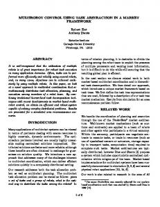
PRINCIPLE OF OPERATION The PMFC is represented schematically in Figure 1. A ceramic package provides a modular foundation for the thermopneumatically-actuated microvalve, a flow orifice, two pressure sensors, and a temperature sensor. Specifications for the PMFCs are shown in Table I. Figure 2 diagrams the system behavior, including feedback. In the following discussion, ‘CO’ refers to the flow orifice, and stands for ‘critical orifice’, even though the flow is not critical for liquids, and is occasionally sub-sonic for gases. ‘NO’ refers to the normally-open microvalve. The flow area of the CO is a constant. The effective flow area of the NO is proportional to the NO membrane stroke, which itself is governed by the power supplied to the microvalve. For gas flow through the CO in the sonic regime, the mass flow is linearly proportional to the absolute pressure upstream of the CO, as shown in Equation (2). The CO thus sets the flow range, consistent with the PMFC specification. Since the CO and NO devices are in series, the intersection of the flow models for each element determines both the sensed pressure Px , and the mass flow. This principle is shown in Figure 3, where the PMFC module inlet pressure is 50 psia, and the module outlet
J. S. Fitch, A. K. Henning, E. B. Arkilic, and J. M. Harris, “Pressure-based mass-flow control using thermopneumatically-actuated microvalves.” In Proceedings, Sensors and Actuators Workshop, pp. 162-165 (Transducers Research Foundation, Cleveland, OH, 1998).
pressure is 200 T. As the NO changes from 100 percent flow to lesser values of flow, the intersection of the NO and CO flow curves falls (the value of Px falls), and the PMFC flow decreases. The CO also sets the flow resolution, as shown in Figure 4 for sonic flow. Taking the derivative of Equation (2) with respect to pressure upstream of the orifice creates the relationship between flow resolution and pressure resolution shown in this figure. For a given pressure sensor resolution and CO area, the minimum flow resolution becomes known. Thus, the CO determines not only the PMFC flow range, but also the minimum flow resolution.
silicon. Lowered defect generation: MFC-generated particles are understood to derive from the number of sealing surfaces, the internal surface roughness, and the internal volume. Compared to TMFCs, the number of seals is reduced, and the internal dead volume is decreased by a factor of two to four. Some liquids of interest in semiconductor processing must be maintained at a relatively low temperature to assure stability. A thermopneumatically actuated microvalve may require temperatures which, at the heater resistor, exceed this threshold temperature. However, proper valve design ensures the silicon membrane contact surface will remain well below this threshold temperature [9].
PACKAGING AND SYSTEM INTEGRATION Figure 5 shows the packaging associated with the PMFC. An on-board E2PROM stores the flow calibration information which relates measured pressure to derived flow, using the appropriate flow equations shown earlier. The ceramic module is attached to a stainless steel manifold, for inclusion of the PMFC into the overall fluid control and distribution system. The feedback control electronics, and their incorporation into this package, are also depicted. Figure 6 shows the natural extension of the PFMC’s modular concept, into a complete, four-channel gas stick. Each channel consists of two vacuum leak-rate shut-off valves, a pressure regulator (derived from the PMFC), and a PMFC. A purge line for the channels is also included.
MEASUREMENTS Figures 7-11 show measurements performed on a 10 sccm PMFC, as well as comparable TMFCs. The tests were performed under the SEMATECH specifications SEMASPEC #92071221 B-STD. The test system is based on a calibrated laminar flow element secondary standard, which is itself calibrated to a high-precision, rate-of-rise primary standard [8]. The figures demonstrate the PMFC has superior performance characteristics when juxtaposed with comparable TMFCs. It also has adequate response time for semiconductor process equipment applications.
DISCUSSION The MEMS-based PMFC offers several benefits relative to the TMFC. Small size: For ‘plug and play’ applications, the PMFC with steel manifold is roughly one inch by 2 inches by 3 inches high, including electronics. In module form only, the size decreases by half. If remote electronics are utilized, the vertical dimension shrinks to one-half inch. Higher resolution: The use of 16 bit A/D for the pressure sensor, and 16 bit D/A for the valve driver, enables very high resolution, which exceeds the SEMATECH specifications. Materials compatibility: The wetted path in the PMFC is comprised of silicon, alumina (ceramic), and appropriate die attach materials. As such, it facilitates flow of all semiconductor processing fluids, save those which contain ionic fluorine, or other ionic elements which etch
CONCLUSIONS We have demonstrated the science and technology required to design and fabricate flow distribution and control devices, specifically PFMCs, suitable for the semiconductor processing industry. These devices are comprised of normally-open microvalves, a microfabricated, passive flow restriction device, two microfabricated pressure sensors, and a temperature sensor. The valve actuation is based on previously developed thermopneumatic techniques. These components have been integrated using advanced packaging techniques, into a ceramicbased module. The MEMS-based PMFC has the benefit of small size, lower cost, higher resolution, materials compatibility, and lowered defect generation, when compared to its TMFC counterpart. The modular nature of the PMFC enables still higher levels of integration – when combined with MEMS-based pressure regulators, and vacuum leak-rate shut-off valves -- in the form of gas sticks, liquid distribution systems, and fullyintegrated, multi-channel gas fluid control and distribution panels.
Acknowledgement This work has been supported in part by DARPA, under Contract #DAAL01-94-C-3401.
REFERENCES 1. M. J. Zdeblick and J. B. Angell, In Proceedings, Transducers ‘87 (1987 Int’l. Conf. Sol. State Sens. and Act.), pp. 827-829 [IEEE, Piscataway, NJ, 1987]. 2. P. W. Barth, “Silicon microvalves for gas flow control.” In Proceedings, Transducers ‘95 (1995 Int’l. Conf. Sol. State Sens. and Act.), pp. 276-279 [IEEE, Piscataway, NJ, 1995]. 3. M. Zdeblick, “Integrated, microminiature electric-to-fluidic valve and pressure/flow regulator.” U.S. Patent 4,821,997 (1989). 4. J. Robertson, “An electrostatically-actuated integrated microflow controller.” Ph.D. dissertation, U. Michigan, 1996. 5. M. Esashi, S. Eoh, T. Matsuo, and S. Choi, “The fabrication of integrated mass flow controllers.” In Proceedings, Transducers ’87, pp. 830-833 [Inst. Elec. Eng. Japan, 1987]. 6. G. Chizinsky, “Recent advances in mass flow Control.” Solid State Technology, p. 85 (September, 1994).
J. S. Fitch, A. K. Henning, E. B. Arkilic, and J. M. Harris, “Pressure-based mass-flow control using thermopneumatically-actuated microvalves.” In Proceedings, Sensors and Actuators Workshop, pp. 162-165 (Transducers Research Foundation, Cleveland, OH, 1998).
7. Frank M. White, Fluid Mechanics. McGraw-Hill (New York, 1979). 8. E. B. Arkilic, M. A. Schmidt, and K. S. Breuer, “A technique for high resolution mass flow measurements at atmospheric pressures.” Experiments in Fluids (1997). 9. A. K. Henning, J. S. Fitch, D. J. Hopkins, Jr., L. Lilly, R. Faeth, E. Falsken, and M. J. Zdeblick, “A thermopneumatically actuated microvalve for liquid expansion and proportional control.” In Proceedings, Transducers ‘97 (1997 Int’l. Conf. Sol. State Sens. and Act.), pp. 825-828 [IEEE, Piscataway, NJ, 1997].
J. S. Fitch, A. K. Henning, E. B. Arkilic, and J. M. Harris, “Pressure-based mass-flow control using thermopneumatically-actuated microvalves.” In Proceedings, Sensors and Actuators Workshop, pp. 162-165 (Transducers Research Foundation, Cleveland, OH, 1998).
Fluid Media: Maximum Flow Rates: Turndown Ratio: Accuracy: Repeatability: Resolution: Response Time: Inlet Pressure Range: Maximum Outlet Pressure: Temperature Range: Power Consumption: Dimensions:
Figure 3: Flow model for a 5 sccm gas PMFC.
Gases/Liquids 1, 10, 100, 1000 sccm/ccm 5:1 (sonic); > 20:1 (subsonic) ± 1% of F.S. ± 0.1% of reading ± 0.1% of reading 500 ms typical 20 to 50 psig 200 Torr 0 to 50°C 1.5 W typical 106 mm x 32 mm x 25 mm
1000
Pressure Resolution (psi)
100
2 µm 5 µm 10 µm
10
15 µm 20 µm
1
25 µm
Table I: Specification for PMFC. 0.1 Normally Open Proportional Valve
0.01 Pressure Sensor
0.001 0.001
0.01 0.1 Flow Resolution (sccm)
1
Figure 4: Pressure resolution required to achieve a given flow resolution, versus CO hydraulic diameter. Ceramic
Inlet
Critical Section Orifice
Outlet
Figure 1: Schematic representation of the PMFC. Flow
Electronics/ Control
Set Point
P in
P out Px
NO
CO
Figure 2: Schematic representation of the compressible flow model for the series combination of a normally-open proportional valve, and a critical orifice. 12
m& CO m & NO 100%
10
75% 50%
Flow (sccm)
8
25%
6
4
2
0 0
10
20
30 P (psia)
40
50
Figure 5: (Top) A MEMS-based PMFC, showing a single module (with protective lid removed), mounted to a stainless steel manifold. The NO microvalve, two pressure sensors, and E2PROM containing calibration coefficients, are visible. (Bottom) A two-module device, with a cut away enclosure revealing supporting electronics boards.
J. S. Fitch, A. K. Henning, E. B. Arkilic, and J. M. Harris, “Pressure-based mass-flow control using thermopneumatically-actuated microvalves.” In Proceedings, Sensors and Actuators Workshop, pp. 162-165 (Transducers Research Foundation, Cleveland, OH, 1998).
2.5
Redwood STEC MKS Unit
Deadband (% Reading)
2
1.5
1
0.5
Figure 6: A four-channel gas panel derived from PMFCs, as well as MEMS-based shut-off valves and pressure regulators. 12
2
4 6 Setpoint (SCCM)
8
10
Figure 9: MFC deadband (resolution) comparisons for PMFC (this work) and TMFCs (other units).
Redwood STEC MKS Unit
10
0 0
Redwood STEC MKS Unit
0.8
8
0.6 6
0.4 Linearity (% FS)
Accuracy (% Reading)
1
4
2
0 0
2
4 6 Setpoint (SCCM)
8
0.2 0 -0.2 -0.4 -0.6
10
-0.8
Figure 7: MFC accuracy comparisons for PMFC (this work) and TMFCs (other units). 0.8
Redwood STEC MKS Unit
0.7
-1 0
2
4 6 Setpoint (SCCM)
8
10
Figure 10: MFC linearity comparisons for PMFC (this work) and TMFCs (other units). 9 Redwood STEC MKS Unit
8 0.5 7 0.4 6 Flow (SCCM)
Repeatability (% Reading)
0.6
0.3 0.2 0.1
5 4 3
0
0
2
4 6 Setpoint (SCCM)
8
10
Figure 8: MFC repeatability comparisons for PMFC (this work) and TMFCs (other units).
2 1
0
10
20
30
40
50
Time (s)
Figure 11: MFC response time comparisons for PMFC (this work) and TMFCs (other units).