86
CSEE JOURNAL OF POWER AND ENERGY SYSTEMS, VOL. I, NO. I, MARCH 2015
Preventing DC Over-voltage in Multi-terminal HVDC Transmission Oluwole D, Adeuyi, Student Member, IEEE, Marc Cheah-Mane, Student Member, IEEE, Jun Liang, Senior Member, IEEE, Luke Livermore, and Qing Mu, Student Member, IEEE
Abstract-This
paper
is
concerned
with
power
reduction
control which is used to avoid DC over-voltage for multi terminal HVDC transmission of offshore wind power. Voltages and frequencies of offshore AC wind farm networks are used for transmitting control signals for the power reduction con trol. These methods do not require fast communication. Power reduction sharing among the offshore wind farms using the different control signals is analysed. The control systems are also compared against the DC chopper method to prevent a DC over voltage. Simulation and experiments are carried out to evaluate the control systems.
Index Terms-AC voltage control, DC chopper, fault ride through, frequency control, HVDC Transmission, multi-terminal HVDC (MTDC), wind power generation.
I.
INTRODU CT ION
A formed by connecting more than two converters through
multi-terminal HVDC (MTDC) transmission network is
DC links. MTDC based on the line commutated converter (LCC) HVDC technology was initially proposed in the 1960s [1], Series and parallel HVDC configurations were discussed in [2], [3], There have been some multi-terminal LCC-HVDC projects in the world [4]. The main difficulty of these systems is to achieve flexible control of power flow direction since the LCCs need to change the polarity of the DC voltage in order to change the direction of the power, In recent years, with the development of the voltage source converter (VSC) HVDC technology, Multi-terminal HVDC based on VSCs has become more attractive, This is due to several factors, including facilitating a DC network which can be easily extended with additional terminals, for both Manuscript received November 20, 2014;revised February 10, 20 IS and February 14, 2015;accepted February 25, 2015. Date of publication March 30,2015;date of current version March 10,2015. Oluwole D. Adeuyi's work was supported by the Research Councils UK,through the HubNet consortium, www.hubnet.org.uk (grant number: EP/I01363611) and the Top and Tail Transformation programme, (grant number: EP/I031707I I). Marc Cheah Mane's and Qing Mu's work was supported by the People Programme (Marie Curie Actions) of the European Union's Seventh Framework Programme FP7/2007-20131 (grant number: 317221, project title MEDOW). Jun Liang's work was supported by the Joint Research Fund for Overseas Chinese, Hong Kong, and Macao Scientists of the National Natural Science Foundation of China (grant number: 5112870 I). O. D. Adeuyi, M. Cheah-Mane, J. Liang, and Q. Mu are with the Institute of Energy, Cardiff University, Cardiff, UK. CF24 3AA. (e-mail:
[email protected];
[email protected];
[email protected];and
[email protected]). L. Livermore is with Siemens, Manchester, UK. M20 2UR. (e-mail:
[email protected]). Digital Object Identifier 1O.17775/CSEEJPES.2015.00011
grid connections and renewable generators. VSC also has the function of flexible power control, through DC current reversal. Additional VSC-MTDC benefits include the ability to black start, no commutation failure, reduced footprint of converter station and independent control of active and reactive power. Multi-terminal HVDC systems are proposed to connect offshore wind farms (OWFs) to the onshore grids in Europe [5], [6]. This technology has also been considered as a key technology for the European Supergrid, which will connect the AC grids of the North Sea countries and offshore renewables through a DC grid [7], In China there are two projects, Nanao Wind Farm Integration and Zhoushan Islands Interconnection, which will become the first VSC-MTDC grids in the world [8], [9]. As a result, MTDC has attracted intensive research. In [10], this technology was used for the integration of wind power and to improve the power quality. A method for DC fault identification and isolation was proposed in [11], In [12], the topologies of offshore DC grids were proposed and compared. The operation characteristics, steady-state operating points and DC power flow were discussed in [13], [14]. The steady state operation was further tested and verified through simulation and experiments [15]. In [16], droop control and design methods were investigated to coordinate DC voltage control and maintain the stability of DC grids. If there is a drop of AC grid voltage near to a converter or disconnection of an AC grid-connected converter, power cannot be completely transferred to the AC grid through this converter. This will cause an imbalance in the power imported and exported from the DC network which will in turn cause the over-voltage of the DC grid. A multi-terminal HVDC network has an advantage over a point-to-point HVDC obtained through the flexibility of the power transfer. Power could be still transferred between the DC and AC grids through other AC grid-connected converters. In [17] and [18] the DC over-voltage has been studied in terms of Fault Ride Through (FRT) capabilities in MTDC grids using wind farms based on fixed-speed induction generators (FSIGs) and FCGs respectively. However, due to the power rating limits of the converters, not all power can be transferred to the AC grids. Appropriate actions will be needed to avoid a DC over-voltage. Several methods have been proposed for the wind turbines during an AC grid fault [19]-[21]. DC over-voltage prevention can be
2096-0042 © 2015 CSEE
ADEUYI el al.: PREVENTING DC OVER-VOLTAGE IN MULTI-TERMINAL HVDC TRANSMISSION
achieved by reducing the amplitude of AC voltages of wind power generators, increasing the frequency of the AC system, through fast communications to de-load the wind turbines or through energy dissipation. An overview of the methods for the DC over-voltage prevention is presented in the section two of this paper. The aim of this paper is to develop control strategies for MTDC grids to avoid a DC over-voltage when the system is subject to various faults (AC grid voltage dip and loss of a grid side converter). In a multi-terminal HYDC system with more than one offshore wind farm, the sharing of wind power reduction is investigated and compared with a method for power dissipation in DC networks. These control strategies are analysed and tested through simulations using PSCADIEMTDC and experiments laboratory scaled HYDC test rig. The control systems are based on local measurements and do not rely on fast communication between converters of the MTDC network, and between wind turbines and wind farm side converters.
II.
OV ERV IEW OF METHODS TO PREV ENT
DC
OV ER-V OLTAGE
DC over-voltage occurs due to a sudden reduction in the power export capability of DC grids. This power imbalance can be due to an onshore AC fault or a converter outage. In case of onshore AC faults, DC networks are required to remain connected to the onshore grid and continue stable operation for AC voltage dips above the worst-case conditions specified in the Grid Code [22]. This is known as fault ride through capability. Fast fault ride through approaches are required to reduce DC over-voltages, where DC currents are limited by constraints within the converters. Several methods to prevent DC over-voltages have been proposed in the literature, which can be broadly grouped as: 1) local control using a DC chopper in the DC network; 2) wind turbine power reduction through local control of offshore AC network; 3) wind turbine power reduction through fast communica tions. The use of a combination of two of these approaches has also been suggested.
87
B. Local Control of Offshore AC Network
As the electromagnetic torque in a wind turbine is propor tional to the square of the AC voltage, one effective method for reducing the active power in the offshore AC network is to reduce this AC voltage. When a DC voltage rise is detected, the wind farm side converter of the HYDC system acts to reduce the voltage amplitude of the offshore AC network so as to reduce the active power imported into the DC network. As a consequence, the DC over-voltage is reduced. In the case of a wind farm installed with full converter generators (FCGs), the AC voltage drop will cause the wind turbine converters to run into its current limit. Then the power output from the wind turbine converter will be limited. Wind turbines are required to have low-voltage ride-through capability [24], [25] for reliable operation. The negative implications of this approach are the potential mechanical stresses caused by a sudden voltage drop. Moreover, for wind farms using doubly-fed induction gener ator (DFIG) turbines, the crowbar circuits may be triggered unexpectedly. In [26] an enhanced version of this technique was used which includes controlled magnetization, thereby reducing the negative effects of fast AC voltage reduction. An alternative to reducing the voltage in an offshore AC network is to increase the frequency of the AC network. The response from the wind turbines will be dependent on the type of machine used. In FSIGs the power output of the machine will naturally reduce. In the case of DFIGs and FCGs, the control system for these machines will have to be modified with a frequency-sensitive outer loop. This was discussed in [27]. This approach is also likely to lead to mechanical stresses as the AC frequency increases. In addition, frequency controllers will need to be improved. As the frequency change is usually relatively slow, this will affect the control performance. Further work in this area has included a combined method, which uses both frequency increase and voltage reduction con trollers. In [28] a two stage controller was implemented. When a small increase in DC voltage is detected, the AC frequency controller is activated to reduce power from the wind farm side. Under more extreme fault conditions, where a larger DC over-voltage is detected, a voltage reduction controller is activated. In [14] the increase in frequency and decrease in voltage was performed simultaneously. The frequency was also used as a control signal for the wind turbines to reduce their mechanical power through pitch angle control.
A. DC Chopper in the DC Network
A robust solution for power reduction is the introduction of a DC chopper circuit into the DC network. In the event of a fault the excess energy within the DC network can be dissipated as heat through this DC chopper circuit. The wind farms are unaffected with this approach. In [23] a DC resistor with a simple hysteresis controller was discussed and implemented for fault ride through. The power dissipation capacity should be designed up to the rated power of a grid side converter, such that it can be effective even during the loss of a terminal. However, the use of a DC resistor with chopper circuit means that additional cost and space are required.
C. Fast Communications
Optic fibre links can be used for fast communications to reduce the active power imported to the DC grid under fault conditions. In [29] droop controllers were designed to de-load wind turbines in the event of an onshore fault. The disadvantage of this approach is the inherent delays in communications, which means that the power reduction may not be quick enough to protect the equipment from damage due to over-voltage.
88
CSEE JOURNAL OF POWER AND ENERGY SYSTEMS. VOL. I. NO. I. MARCH 2015
WFC
1
Vwf
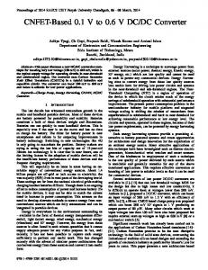
Fig. 1. Offshore wind farm scheme based on FCGs.
III. C ONTROL
AVOID DC OVER -VOLTAGE MTDC SCHEMES
DESIGN TO
O.
(1), when the DC voltage reaches Vrnax, cx becomes zero, and the AC voltage
IN
The power reduction control methods for the offshore wind farms connected to HVDC schemes are discussed and anal ysed. It was assumed that offshore wind turbines are all FCGs as shown in Fig. 1. The key issue for the wind turbines is to sense the rise of the DC voltage of the HVDC scheme without using fast communications. In point-to-point (P2P) HVDC transmission, wind power reduction methods to avoid DC over voltage have been presented in the literature. Compared to the P2P schemes, the major challenge for MTDC configurations is to determine the contribution of power reduction from several wind farms. When there is a DC voltage rise in the HYDC grid, two methods were used for the wind turbine converters to know this information without using fast communication. One method is to reduce the amplitude of the wind farm AC voltage and another to increase the frequency of the voltage. By controlling the wind farm side VSCs of the MTDC grid, the amplitude offshore AC voltage or the frequency of the offshore network are changed. As a result, the wind turbines sense these changes and reduce their power outputs accordingly. The power reduction capabilities of the two methods were analysed and compared. The power sharing duties of wind farms connected to different terminals of an MTDC scheme were studied using both methods. These two methods were also compared with a method using a DC chopper resistor. In addition, the performance of these three DC over-voltage reduction techniques were tested using an experimental plat form.
cxVwCrated
=
=
(2)
For an offshore wind farm based on FCGs and connected to the MTDC grid through a VSC, in normal operation there is no reactive power requirement for the wind turbine converters. Therefore, only the real power will be transferred through the wind turbine converter. The total power of a wind turbine is
Pwt
3.
=
Vwt . Iwt
y'2 y'2'
(3)
where Iwt, Vwt are the amplitudes of the line current and voltage of the wind turbine converter. With the drop of the wind farm AC voltage, the wind turbine converter voltage decreases at the same rate (as it is transformed voltage of cx . Vwt_rated. For a given initial Vwr) and therefore Vwt wind power PwtO, the output current from the wind turbine converter Iwt increases with the decrease in Vwt. The actual output power will remain as the initial value until the output current reaches its limit IwUrnt. If the AC voltage continues to decrease, the output current is maintained at the limit through the wind turbine converter control. Thus, the power output from each wind turbine is reduced to PwUrnt, given in (4), =
P,wt_Irnt
=
3·
Vwt
;;:;' v2
Iwt Irnt
=
In v2
3.
-
2
cx · Vwt-rated ' Iwt-Irnt, (4)
which is a function of cx. Then, the existing fault-ride through function [24] of the wind turbine reduces the wind power generation accordingly in order to maintain the power balance and DC voltage of the wind turbine converter. Therefore the actual output power from each wind turbine is: when Iwt--0-
uQ;
�
�
:2:", >
:2: '" >
�
_280 > ";;;270 �OO fi � 260 s> 2S0 u o 240�
g�
(e)
[1.000
uQ; �
0::
co
Q)
�6 is
1
CoCo .s O
soor--I--J----4
Time (5)
(b)
2
4
Time (5)
6
_280 > ";;;270 "00 f:2 � 260 s> 2S0 u 0 240 0
LJ1
.�� 1
(e)
-0
�
4
Time (5)
"'os tlO
�� .
==�----'.======;== o�=-�--=�==;== ·., s 0t= � � '0
0
2
4
Time (5)
(d)
(d)
Fig. 5. Experimental results (left side) and simulation results (right side) increasing offshore AC network frequency. (a) Voltage of AC grid 1. (b) Power of converters. (c) DC voltage WFCI. (d) Ratio of frequency increase of the AC wind farm voltage 1.
Fig. 6. Experimental results (left side) and simulation results (right side) using chopper resistor. (a) Voltage of AC grid 1. (b) Power of converters. (c) DC voltage WFCI. (d) Duty ratio of reduction of DC chopper. '.'
GSC2
Fig. 6(d). Finally the DC voltage reduced from its peak value of 269 V back to 245 V. The DC chopper circuit control is simple and needs only the local DC voltage as the control input. The control response is better than the methods of voltage reduction or frequency increase. B. Disconnection from an AC Grid
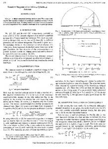
In this case, a three-terminal HVDC grid with one offshore converter and two onshore converters, as shown in Fig. 7, was used. The rated voltage of the offshore AC network is 120 V. The power rating of the grid side converters, GSC1 and GSC2, is 1 kW each. The power rating of the wind farm and the offshore converter is 2 kW. The initial wind power injected into the HVDC grid through the wind farm side converter, WFC1, is 1.5 kW. The GSC1 and GSC2 used the droop control proposed in [13] and shared the power in proportion 6: 1. It was assumed there was a sudden failure of the GSC2 at 1 s, which resulted in the disconnection of the HVDC grid from the AC Grid 2. Since the injected wind power was larger than the power rating of the GSC1, the power must be reduced in order to avoid a DC over-voltage of the HVDC grid. Fig. 8 shows the results when the method of reducing the AC wind farm voltage was used. When the power through the GSC2, Pgs2, became zero, the DC voltage, Ewf, started to increase. Through the control system, the amplitude of
Fig. 7. One offshore converter connected through a wind farm and two onshore converters.
the AC wind farm voltage, Vwf, was reduced. The power output from the wind turbines was reduced and thus the wind power injected into the HVDC grid decreased from 1.5 kW to approximately 1 kW. The DC voltage increased from 252 V to approximately 270 V. Fig. 9 shows the results when the method of increasing the AC wind farm frequency was used. When the power through the GSC2, Pgs2, became zero, the DC voltage, Ewf, started to increase. Through the control system, the frequency of the AC wind farm was increased from 50 Hz to approximately 54 Hz. The ratio of frequency increase, (3, is shown in Fig. 9(c). The power output from the wind turbines was reduced and thus the wind power injected into the HVDC grid decreased from 1.5 kW to 1 kW. The DC voltage increased from 252 V to approximately 270 V. Fig. 10 shows the results when a DC chopper resistor was
92
CSEE JOURNAL OF POWER AND ENERGY SYSTEMS, VOL. I, NO. I, MARCH 2015
�1,5001-.... U � 1.000 r-' 00 f-D:;; '" 500 > n 0 I« 0
�t500� '::' U � 1,000 00 f-D- 500 :;; '"
-WFC1 -GSC1 GSC2
>
«
4
-GSC:z
O-
tl
Time(s)
-WFC, -GSC,
2: 270 '" co
_
fr � 260 3;:g g 250
>
2: 270 '"
4
��
o=> c-
c-
:8�
"0",
!g �
&."=5 '0 �
0.6
LL
...,3;: ro.....
.Q3;:
�o
4
0
0:::0
4
Time (s)
(a) _
co
260
Time(s)
(b)
SO.6
S�
�
0.4
6
OU U o
�IM
-S ,g
�
0.2 0
-
. � 0'6 g
�IM
0.6
Time (s)
2: 270 '"
&:�
260
o�
4
4
Time(s)
Time (s)
Time(s)
1
0.2 0
0l-J:::;::====;=
3;:> 3;:g g 250 g 250 0�--�----�4--�- L---�----�4--�--
� �O.8
=>co
��O.8
Ji
�
co
(b) .� � u'"
� 4 Time(s)
'"
0
Time(s)
�
-270
co
�� 260 3;:g g 250 0
Q)
� o
4
Time(s)
(a) _
�1,5001-+------ � t500r------ U i 1,000 �L..._------ U � tOoor"l- ------W-FC, 00 -GSC1 � � 500 ..-.--GSC4 � Q... 500 _WFC1 :::2: _GSC1 :;;.� S� �> o �� �� ��G �-
L---�----�----- �4 6
OU U 0
Time (s)
0.2 0
U
0
L---�----�----- � 4 6
Time (s)
(C)
(C)
Fig. 8. Experimental results (left side) and simulation results (right side) with reduction of offshore AC network voltage. (a) Power of converters. (b) DC voltages. (c) Ratio of voltage reduction,
Fig. 10. Experimental results (left side) and simulation results (right side) using chopper resistor. (a) Power of converters, (b) DC voltages, (c) Duty ratio of reduction of DC chopper.
�1,500 1,000 500>-
U � 00 f-D� (]) >
VI.
_WFC1 _GSC1 o�������G�SC�2 4 o Time(s)
�
> lJ
(a)
-270
�k
_
260
3;:g g 250 t
L---�---- �---- �-4
0
Time(s)
2: 270 '" co
ft � 260 3;:g g 250 0�--�----�4--�- Time (s)
(b) � §5s
0.1
u:-
0.05
0
0
::J a. crQ)
u:
o� .g
�
� c_ � 6.. � ...
rr-
�
0_ .Q 0
L---�----�4--�- � Time(s)
0.1
� 0.05 4
Time(s)
(C) Fig. 9. Experimental results (left side) and simulation results (right side) increasing offshore AC network frequency. (a) Power of converters. (b) DC voltages. (c) Ratio of frequency increase,
used, When the power through the GSC2, Pgs2, became zero, the DC voltage, Ewf, started to increase. Through the chopper circuit control, the duty ratio was determined. The chopper resistor consumed the excessive power in the DC grid and the DC voltage was maintained. Through the simple and local control of the chopper resistor, there is no requirement to reduce the input power from the wind farms, as Pwf in Fig. LO(a).
CONCLUSIONS
The methods for preventing DC over-voltage in multi terminal HVDC networks were analysed and compared, Two power reduction control methods were designed for a MTDC transmission, The two methods are particularly for the offshore wind farms with FCGs. The first method is to reduce the amplitude of the offshore AC network voltage. The wind turbine converters will respond to the voltage reduction using the low voltage ride through function already installed and reduce the power output from the wind turbines. When this method is used for multiple offshore wind farms connected to HVDC networks, the wind farms with larger initial power outputs or smaller current ratings will reduce the power output first. The second method is to increase the frequency of the offshore AC network. The wind turbine converters will reduce their power outputs by responding to the frequency increase. Therefore, this method needs the wind turbine converters to install an auxiliary frequency loop control. When this method is used for multiple offshore wind farms connected to a HVDC network, all the wind farms will reduce their power outputs at the same rate, These two methods were compared with another method using a DC chopper resistor through simulation and experi ments using a MTDC system, The DC chopper resistor method is simple and needs only local control signal. It can achieve better control performance than the power reduction methods but with extra cost and equipment size, On the other hand, the power reduction methods based on the voltage reduction and frequency increase remove the need of fast communication between the offshore converters and wind turbines. They also do not require extra equipment to implement the control ideas, Simulation and experimental results under various faults
ADEUYI el al.: PREVENTING DC OVER-VOLTAGE IN MULTI-TERMINAL HVDC TRANSMISSION
have demonstrated the feasibility of the power reduction controllers to prevent DC over-voltages. ApPENDIX A TABLE AI CONTROL PARAMETERS-AMPLITUDE REDUCTION CONTROL Parameters
Value
Rated AC wind farm voltage, Vwf
rat
93
ApPENDIX
B
TABLE AV SPECIFICATIONS AND PARAMETERS OF THE TEST RIG Devices
Voltage source converters
120 V
Specifications
Equipment rating
Operating rating
Power
IO kW
2 kW
AC voltage
415 V
120 V
DC voltage
800 V
250 V
Topology TABLE All CONTROL PARAMETERS-DC CHOPPER CONTROL
Motor-generator unit
2-level, 3-phase no neutral
Power
5.65 kW
2 kW
Rotor speed
3000 rpm
1500 rpm
294 V
147 V
Parameters
Value
AC voltage (L-L rms)
Chopper resistance, Rchopper
450
Pole number
6
LlO, L20, L30
2.2 mH
Lwfl, Lgsl
2.4 mH
AC inductors TABLE AIII CONTROL PARAMETERS-FREQUENCY INCREASE CONTROL Parameters
Value
Rated AC wind farm frequency, fwCrat
50 Hz
Frequency adjustment coefficient, kf
0.2
TABLE AIV CONTROL PARAMETERS-DC VOLTAGE PARAMETERS FOR EACH CONTROL Parameters
Value
Rated DC voltage, Vdc_rat
250 V
Threshold DC voltage, Vdc_trig
Maximum DC voltage, Vdc
trig
260 V 280 V
REFERENCES [I] J. Reeve, "Multiterminal HVDC power systems," IEEE Transactions on Power Apparatus and Systems, vol. PAS-99,no. 2, pp. 729-737, March 1980. [2] U. Lamm,P. Uhlmann,and P. Danfors,"Some aspects of tapping HVDC transmission," Direct Current, vol. 8, pp. 124-129,1963. [3] J. Reeve and J. Arrillaga,"Series connection of converter stations in an HVDC transmission system," Direct Current, vol. 10, pp. 72-78, 1965. [4] T. Sakurai,K. Goto,and S. Irokawa,"A new control method for multiter minal HVDC transmission without fast communications systems," IEEE Transactions on Power Apparatus and Systems, vol. PAS-I02,no. 5,pp. 1140-1150, 1983. [5] L. Yao, L. Xu, M. Bazargan, N. MacLeod, and L. Schmitt, "Large offshore wind farm grid integration-chaUenges and solutions," in 2008 CIGRE Session, 2008. [6] W. Kling, R. Hendriks, and J. den Boon, "Advanced transmission solutions for offshore wind farms," in 2008 IEEE Power and Energy Society General Meeting-Conversion and Delivery of Electrical Energy in the 21st Century, July 2008, pp. 1-6. [7] D. Van Hertem and M. Ghandhari, "Multi-terminal VSC HVDC for the European supergrid: obstacles," Renewable and Sustainable Energy Reviews, vol. 14, no. 9, pp. 3156-3163,Dec. 2010. [8] DNV GL. (2014, July). DNV GL advises on world's first multi terminal VSC HVDC transmission project integrating clean en ergy into China's regional power composition mix. [Online]. Available: http://www.dnvgl.com/news-events/news/word-record-hvdc transmission.aspx.
DC inductors DC capacitors
Rwfl, Rgsl
0.150
Cl,C2,C3
1020/-iF
dSPACE
DSI005
Unidrive
Control technique SP2403
[9] NR Electric. (2014,July). Zhoushan multi-terminal VSC-HVDC project was put into service. [Online]. Available: http://www.nrec.com/en/news content-253.html. [l0] w. Lu and B. T. Ooi, "Premium quality power park based on multi terminal HVDC," IEEE Transactions on Power Delivery, vol. 20,no. 2, pp. 978-983, April 2005. [11] L. Tang and B. T. Ooi, "Locating and isolating DC faults in multi terminal DC systems," IEEE Transactions on Power Delivery, vol. 22, no. 3, pp. 1877-1884, July 2007. [12] O. Gomis-BeUmunt, J. Liang, J. Ekanayake, R. King, and N. Jenkins, "Topologies of multiterminal HVDC-VSC transmission for large off shore wind farms," Electric Power Systems Research, vol. 81,no. 2,pp. 271-281, Feb. 2011. [13] X. P. Zhang, "Multiterminal voltage-sourced converter-based HVDC models for power flow analysis," IEEE Transactions on Power Systems, vol. 19, no. 4, pp. 1877-1884,Nov. 2004. [14] J. Liang, "Control of multi-terminal VSC-HVDC transmission for offshore wind power," in Proc. 13th European Conference on Power Electronics and Applications, 2009, pp. 1-10. [15] J. Liang, T. Jing, O. Gomis-Bellmunt, J. Ekanayake, and N. Jenkins, "Operation and control of multiterminal HVDC transmission for offshore wind farms," IEEE Transactions on Power Delivery, vol. 26, no. 4, pp. 2596-2604, Oct. 2011. [16] T. Haileselassie,K. Uhlen, and T. Undeland, "Control of muItiterminal HVDC transmission for offshore wind energy," in Proc. Nordic wind power conference, Bornholm (Rinnp),Danmark, 2009, pp. 10-11. [17] O. Giddani,G. Adam,O. Anaya-Lara,K. Lo et al., "Grid integration of offshore wind farms using multi-terminal DC transmission systems (MT DC)," in Proc. 5th lET International Conference on Power Electronics, Machines and Drives (PEMD 2010). lET, 2010, pp. 1-6. [18] c. Moreira and B. Silva,"Operation and control of multiterminal HVDC grids for AC fault ride through compatibility," in Proc. 2014 IEEE International Energy Conference (ENERGYCON), 2014, pp. 287-294. [19] A. A. van der Meer, R. L. Hendriks, and W. L. Kling, "A survey of fast power reduction methods for VSC connected wind power plants consisting of different turbine types," EPE wind energy, pp. 23-24,2009. [20] L. Harnefors, Y. Jiang-Hafner, M. Hyttinen, and T. Jonsson, "Ridethrough methods for wind farms connected to the grid via a VSC-HVDC transmission," 2007. [21] R. L. Hendriks, R. VOlzke, and W. L. Kling, "Fault ride-through
94
[22]
[23]
[24]
[25]
[26]
[27]
[28]
[29]
CSEE JOURNAL OF POWER AND ENERGY SYSTEMS, VOL. I, NO. I, MARCH 2015
strategies for vsc-connected wind parks," in EWEC 2009: Europe's P remier Wind Energy Event, Marseille, France, pp. 16-19,March 2009. ENTSO-E. (2014). Draft network code on high voltage direct current connections and DC-connected power park modules. [Online]. Avail able: https://www.entsoe.eulDocuments/Network codes documents/NC HYDC/140430-NC HYDC.pdf. L. Xu and L. Yao, "DC voltage control and power dispatch of a multi terminal HYDC system for integrating large offshore wind farms," lET Renewable Power Generation, vol. 5, no. 3, pp. 223-233, May 2011. D. Nguyen and M. Negnevitsky, "A review of fault ride through strategies for different wind turbine systems," in 20th Australasian Universities Power Engineering Conference (AUPEC). IEEE, 2010, pp. 1-5. A. Mullane, G. Lightbody, and R. Yacamini, "Wind-turbine fault ride through enhancement," IEEE Transactions on Power Systems, vol. 20, no. 4, pp. 1929-1937,Nov. 2005. c. Feltes and H. Wrede, "Enhanced fault ride-through method for wind farms connected to the grid through YSC-based HYDC transmission," IEEE Transactions on Power Systems, vol. 24, no. 3, pp. 1537-1546, 2009. L. Xu,L. Yao,and C. Sasse,"Grid integration of large DFlG-based wind farms using YSC transmission," IEEE Transactions on Power Systems, vol. 22, no. 3, pp. 976-984, 2007. A. Egea-Alvarez, A. Junyent-Ferre, O. Gomis-Bellmunt, J. Liang, J. Ekanayake, and N. Jenkins, "Operation and control of YSC-HYDC multiterminal grids for offshore wind," in Proc. 14th European Confer ence on Power Electronics and Applications (EPE 2011), Aug 2011,pp. 1-9. G. Ramtharan, A. Arulampalam,J. Ekanayake,F. Hughes,and N. Jenk ins, "Fault ride through of fully rated converter wind turbines with AC and DC transmission," lET Renewable Power Generation, vol. 3,no. 4, pp. 426-438, December 2009.
Oluwole D. Adeuyi (S'l!) was born in Owo,Ondo State,Nigeria in 1988. He received a B.Sc. degree in ElectricallElectronics Engineering from the Univer sity of Agriculture, Abeokuta, Ogun State, Nigeria in 2010, and M.Sc. degree in Electrical Energy Systems from Cardiff University, Cardiff, UK in 2012. In 2012 he joined the Institute of Energy within Cardiff University, Cardiff UK, where he is currently a Research Assistant and PhD. Student. Mr. Adeuyi was recipient of the World Energy Forum International Sustainable Energy Essay Contest First Prize in 2012, and the Eurelectric Student Essay Contest First Prize in 2014. His current research is on power systems,renewable energy generation,HYDC transmission and control.
Marc Cheah-Mane (S'14) received the degree in industrial engineering from the School of Industrial Engineering of Barcelona (ETSEIB), Technical U niversity of Catalonia (UPC), Barcelona, Spain, in 2013. He was a researcher in Centre dinnovacio Tec nologica en Convertidors Estatics i Accionaments (CITCEA) from 2010 to 2013. Since October of 2013, he is pursuing a Ph.D in Cardiff University, Cardiff,Wales. His research interests include renew able energies, power converters, high-voltage direct current systems, electrical machines and microgrids. Jun Liang (M'02 - SM'12) received the B.S. degree from Huazhong University of Science and Tech nology, Wuhan, China, in 1992, and the M.S. and Ph.D. degrees in electrical engineering from the China Electric Power Research Institute (CEPRl), Beijing, China, in 1995 and 1998, respectively, all in electrical engineering. From 1998 to 2001, he was with CEPRI as a Senior Engineer. From 2001 to 2005, he was a Research Associate in the De partment of Electrical and Electronic Engineering, Imperial College London,U.K. From 2005 to 2007, he was a Senior Lecturer at the University of Glamorgan. He is currently a Senior Lecturer at the School of Engineering, Cardiff University, Cardiff, U.K. His current research interests include FACTS/HYDC,power electronics, power system stability control, renewable power generation, and distributed generation. Luke Livermore received the B.Eng degree from the University of Nottingham in 2007 and the Ph.D degree from Cardiff University in 2012, both in electrical and electronic engineering. He is current ly a senior HYDC design engineer for Siemens in Manchester, UK. His research interests include HYDC system design,multi-terminal HYDC,power system operation and stability control.
Qing Mu (S'12) was born in Changzhou, China, in 1983. He received the B.Sc. degree in Automatic Control from Institute of Electrical Engineering, Zhejiang University, Hangzhou, China, in 2005 and the M.Sc. and Ph.D. degrees from China Electric Power Research Institute, Beijing, China, in 2010 and 2013, respectively. He is currently an Experi enced Researcher in Cardiff University. His research interests include power systems, HYDC, renewable energy generation.