chromatography (SEC) has been the ... binding to the columns (8) â as we ..... inset shows SEC analysis of the same sample, carried out using a TOSOH ...
B
I O
PR
O C E S S TECHNICAL
Aggregation Analysis of Therapeutic Proteins, Part 3 Principles and Optimization of Field-Flow Fractionation (FFF) Tsutomu Arakawa, John S. Philo, Daisuke Ejima, Haruna Sato, and Kouhei Tsumoto
M
any proteins are marginally stable in solution, undergoing conformational changes due to various stresses during purification, processing, and storage (1). Elevated temperature, shear strain, surface adsorption, and high protein concentration can lead to aggregation and eventual precipitation (2). Irreversible aggregation is a major problem for long-term storage stability, shipping, and handling of therapeutic proteins, as has been extensively reviewed (3). We discussed some mechanisms of aggregation at length in Part 1 of this review (4). Size-exclusion chromatography (SEC) has been the primary method for detecting and quantifying protein aggregation (5–7). However, the validity of SEC results is often questioned because aggregates can be lost through nonspecific binding to the columns (8) — as we evaluated in Part 1 (4). Thus, column PRODUCT FOCUS: PROTEINS, ANTIBODIES PROCESS FOCUS: ANALYSIS AND DOWNSTREAM PROCESSING
WHO SHOULD READ: QA/QC, PROCESS DEVELOPMENT, MANUFACTURING, AND ANALYTICAL PERSONNEL
KEYWORDS: FIELD-FLOW FRACTIONATION, AGGREGATION, CROSS FLOW LEVEL: INTERMEDIATE 52
BioProcess International
N OVEMBER 2007
WWW.PHOTOS.COM
(matrix)-free techniques, such as analytical ultracentrifugation (AUC), field-flow fractionation (FFF), and dynamic light scattering (DLS) now find increasing application in aggregation analysis. We reviewed AUC and DLS in Part 2 (9). Here we review FFF, a technology that has existed for nearly 40 years but has only recently been introduced into biotechnology. Because this technology is probably least familiar of the matrix-free techniques and requires the most method optimization, we start by detailing the operating steps and optimization methods using separations of monoclonal antibodies as examples.
FFF TECHNOLOGY
FFF is a matrix-free technique invented in the 1970s and developed primarily by Giddings (10).
Substantial improvements in FFF equipment have enhanced its capabilities and robustness and hence its potential for analyzing protein aggregation. This application is still rather new, however, and we can probably expect further advancements as use and experience grow. Nevertheless, its broad dynamic range of size separation has already found novel uses such as fractionation of prion aggregates (11) and virus particles (12, 13). Principle of FFF: FFF uses the laminar flow of solvent running through a narrow channel made of two flat surfaces, as shown in Figure 1 (current models have a tapered shape from the top view, as in Figure 2). For laminar flow the flow rate has a parabolic dependence on distance from the flat top and bottom surfaces of the flow channel, reaching a
54
BioProcess International
N OVEMBER 2007
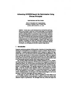
Figure 1: (A) The principle of field-flow fractionation (FFF), in which the lengths of the two arrows indicate different velocities, the cross flow in this case causing smaller molecules to populate in the center due to larger diffusion coefficient toward the center of the channel, as indicated by the length of the arrows. A cross field drives the analyte molecules toward the lower wall where the flow is slower. When the cross field is due to cross flow, larger molecules with lower diffusion stay closer to the wall; (B) basic flow direction of asymmetric flow (afFFF).
� ����������
maximum at the center (Figure 1A). A force perpendicular to the flow of solvent (the “cross field”) is applied to separate the analyte molecules. When this cross field is generated by a cross flow (flow FFF), the separation is based on the analyte’s diffusion coefficient. For an applied electric field (electrical FFF), separation is based on electric charge, whereas for a centrifugal field (sedimentation FFF) it is based on molecular weight. A cross flow is by far the most widely used cross field for protein analysis; consequently, the technique is often simply called FFF or fFFF (flow FFF). The most recent instruments use asymmetric cross flow and hence are called asymmetric flow FFF (afFFF). Such instruments are now commercially available. Figure 1B shows the general principles of afFFF. Only the lower plate is a semipermeable membrane (shown by a dotted line). Upon application of cross flow, water and small molecules pass through the semipermeable membrane while large molecules including proteins are retained and pushed against it. The pore size of the membrane determines the size of retained molecules. The confinement of protein molecules near the membrane is, however, opposed by diffusion. Smaller particles have higher diffusion coefficients and, on average, will stay farther from the membrane (where the flow is faster), as shown in Figure 1B (the confined box of Panel A). Thus, they travel faster along the channel than the larger particles with lower diffusion coefficients, as shown in Panel B. Proteins therefore elute according to their size, with smaller particles eluting first. The elution profile can be monitored by suitable detectors, such as UV absorbance, refractive index, and/or light scattering (Panel C). Instruments: The actual operating details depend on the instrument. We know of only two models of commercial afFFF currently available for protein aggregation analysis. One is made by Wyatt Technology (Santa Barbara, CA, www.wyatt.com); Figures 2A and 3A illustrate its flow diagram. The other instrument from
�����������
�����
������
� �������
�����
���������������������� ���������������������������
������
������� �������
�����������
��������� Figure 2: Schematic diagram of an FFF instrument; (A) Wyatt instrument; (B) Postnova instrument ����
�
������������
���������
��������� �������������
�����
���������
�
��������� ������
��������� �������������
������������
������
���������
������ ���������
��������
Figure 3: Flow diagram of FFF; (A) Wyatt instrument; (B) Postnova instrument ������������������ ��������������� �������������������������
� ��������������
������������������ ����������� ��������
������������������
�����
��
�
�����������������������
�������������������
���������������
�����������
������������������� ���
����� ������������������� �������������
��������������
������������������
������������������
�����
����������� ��������
���������������
�����������
�������������������
��������������������
�����
� ���������� ��������������
�������� ���������
�����������
�����
���������
���������������
���������
Postnova Analytics (Salt Lake City, UT, www.postnova.com) is depicted in Figures 2B and 3B. Four major differences between the two instruments are the number of pumps, the positions of the injection- and focusing-flow ports, and the presence of a purge-flow port in the Postnova instrument. The Wyatt instrument uses only one pump (Figure 2A), and the direction and rate of its flow are controlled by three flow-regulator valves (Figure 3A). Figure 3A (Panel B) shows the normal operating-flow mode of the Wyatt instrument, in which the injection valve (valve 2) is closed, and the regulator valves split the inlet flow between the channel 56
BioProcess International
N OVEMBER 2007
flow and cross flow (valve 3). For injection mode, the three regulator valves divide the flow into inlet, injection, focus, and cross flows. The Postnova instrument uses three independent pumps to control the flow (Figure 2, Panel B). The second difference is the position of the sample injection ports. Sample is injected through the inlet port for the Postnova instrument, whereas it is injected through an independent injection port in the Wyatt. The third difference is the port for the focus flow. For the Wyatt instrument it is identical to the outlet of the flow channel, whereas the Postnova has an independent port close to the sample injection port
(which is also the inlet) (Figure 2B and 3B). The last difference is the presence of a purge port in the Postnova instrument (Figures 2B and 3B). This port discharges the upper portion of the laminar flow, which contains no proteins, as is evident in Figure 1B. In the Wyatt instrument the entire outlet flow goes to the detectors, whereas removal of the upper portion in the Postnova reduces dilution of the sample and hence enhances detector sensitivity. Although not explicitly shown in these diagrams, another important operating variable is the height of the flow channel (the plate separation), which affects resolution and sensitivity. This channel height is determined by spacers of varying thickness. As would be expected, thicker spacers cause more dilution and affect the shape of the laminar flow. Although more protein can be loaded to compensate for that dilution, we have insufficient data at this time to predict how plate separation affects the optimization of flow parameters. Therefore, typically all flow parameters must be reoptimized after the plate separation is changed. In addition, the type and pore size of the membrane, together with the choice of elution solvent, affect the degree of nonspecific binding (sample recovery). Basic Operation: Although the principle is simple, fFFF requires optimizing multiple parameters. Because we are more familiar with the Wyatt instrument, we limit our description to its operation. Figure 3A and Table 1 illustrate the basic operating steps. In Step 1.1, the membrane is fully equilibrated with the running solvent, as indicated by stable detector baseline signals (UV, refractive index, and light scattering). This step establishes a constant flow rate, essential for a stable laminar flow. At this stage, the flow is established along the channel and through the membrane (cross flow) at the desired flow rates. Once the membrane is equilibrated, the outlet flow is reversed so that solvent flows along the channel from both the inlet and outlet toward the center (Step 1.2). This determines the position at
which an injected sample is focused. The sample is then injected through the injection port (Step 2). After sample injection, solvent is further supplied from both the inlet and outlet, leading to focusing the proteins near the wall at a position where the net flow along the channel is zero (Step 3). This focusing step generates a concentration gradient of the injected sample (Figure 1B, confined box). Once the concentration gradient is established, normal channel flow resumes (Step 4), and if desired, the cross flow can be varied. Note that the focusing step does not appear to be an absolute requirement if cross flow is maintained during elution. Maintaining cross flow will keep the concentration gradient from the wall, whereas relaxing cross flow will cause a shallower concentration gradient for all the particles. As laminar flow proceeds along the channel, particles are separated based on the concentration gradient away from the channel wall.
Channel Cross Focus Injection Detector Flow Flow Flow Flow Flow (mL/min) (mL/min) (mL/min) (mL/min) (mL/min)
Mode
Pump
1.1
1
1
Elution
3.8
1.5
2.3
0
0
1.5
1.2
1
2
Focus
3.5
—
2.0
2.0
0
1.5
2
2
4
Focus + Injection
3.5
—
2.0
2.0 (1.6)
0.4 (0.32)
1.5
3
1
5
Focus
3.5
—
2.0
2.0
0
1.5
4.1
30
35
Elution
3.8
1.5
2.3
0
0
1.5
4.2
4
39
Elution
1.5
1.5
0
0
0
1.5
4.3
30
69
Elution + Injection
1.5
1.5
0
0
0.4 (0.19)
1.5
Figure 4: Flow rate and direction before, during, and after sample injection and during focusing ����
�������
���������� ���������
��������� ������������������ ����
���� ������������������� ��������
���������
Five operating parameters can be varied, as shown in the flow diagrams of both instruments (Figure 3): the flow-channel flow rate; the ratio of inlet and reverse flows for injection and focusing; the injection-flow rate; the cross-flow rate; and the focusing time. Flow-Channel Rate: In the following experiments, we primarily used the Wyatt instrument, but the same lessons should apply to use of the Postnova instrument. Table 1 summarizes the exact protocol for the Wyatt instrument, which we used to test the various parameters. That table also shows flow directions and rates (expressed by different line thickness), as well as actual flow rates. In a typical cycle of an afFFF experiment, the flow channel is equilibrated (Step 1) before sample injection for two minutes with elution solvent. This first step comprises two substeps. In Step 1.1, the pump is set at a flow rate of 3.8 mL/min, which is split into a channel flow of 1.5 mL/min and a cross flow of 2.3 mL/min — as BioProcess International
Step
Total Time Time (min) (min)
������������������
THE EFFECTS OF OPERATING VARIABLES
58
Table 1: Flow parameters (flow directions and rates are expressed by different line thicknesses)
N OVEMBER 2007
���������
���������
��������
�������� ����
����
��������
shown in Figure 3A (Panel 2), A = b = 3.8 mL/min, X = 2.3, and Y = 1.5 (channel flow). This is followed by a one-minute period of focusing (Step 1.2) using a pump set at 3.5 mL/min: A = 3.5, of which 0.1 mL is used as an inlet flow (b = 0.1, Table 1) and 1.9 mL as a focus flow (d = 1.9). The total inlet flow and focus flow (2 mL/min) permeates the membrane as a cross flow (Figure 3A, Panel 1, marked X = b + c + d with c = 0). The ratio of those two flows, 0.05:0.95, provides two opposite flows converging near the sample injection port (Figure 4A).
The remaining 1.5 mL/min of pump flow goes directly to the detector (Y = 1.5 mL/min in Figure 3A, Panel 1). After one minute of focusing, a sample is injected at a flow rate of x mL/min (set at 0.4 mL, for example, in Table 1, Step 2). Because x mL/min of 2 mL/min is used as an injection flow, the remaining (2 – x) mL/min is split into the inlet flow and focusing flow at a 0.05:0.95 ratio as shown in Figure 4. This corresponds to b = 0.08 and d = 1.52 with c = 0.4 (Table 1 and Figure 3A, Panel 1).
�
�
����
�
��������������
����
��������������
�
��
����
���� ��
����
����
��� ���� ��� ���
�
���
��� ���
� ����
����
����
����� ����
����������
Thus, focusing is maintained during injection at the same position in the channel. After two minutes of injection, an additional one minute of focusing is continued (Step 3) using the same setting as prefocusing equilibration, x = 0 (Figure 4C). Finally, elution is initiated by reversing the focus flow (Step 4.1) but increasing the pump setting to 3.8 mL/min (identical to Step 1). After 30 minutes elution, cross flow is nullified, and injection flow is performed for cleaning (Steps 4.2 and 4.3). A typical elution pattern using a MAb-b (the same antibody example used in Parts 1 and 2 of this article series) is plotted in Figure 5, where horizontal bars indicate the length of each step. It is interesting to point out that the refractive index (RI) signal closely follows the direction of channel flow. The RI signal is at a higher level when the channel flow is in the normal direction and the cross flow is applied (for example Steps 1.1 and 4.1). When there is no cross flow (Steps 4.2 and 4.3) or the outlet flow is in reverse direction (Steps 1.2, 2 and 3), the RI signal is at a lower level. The RI signal drifts during Steps 4.2 and 4.3, perhaps due to the change of cross flow to zero after elution Step 4.1 and hence an unstable channel flow. As soon as elution flow begins (Step 4.1), a sharp peak (arrow 1) appears, corresponding to an injection spike. A peak at ~9.5 min corresponds to the monomeric MAb-b (arrow 2). 60 BioProcess International
N OVEMBER 2007
Additional peaks (arrows 3 and 4) appear as soon as cross flow is stopped (Step 4.2). Although two peaks are apparent in the LS signal, the peak areas cannot be quantified for both peaks. Peak 3 occurs during the descending RI signal due to the crossflow change to zero. There is no apparent RI signal for peak 4, indicating that this material has a very high molecular weight (high enough to scatter significant amounts of light even though the concentration is too low to detect by RI). As shown in Figure 5, the monomeric MAb-b peak is skewed. Hence, we examined the effects of flow parameters on the peak shape and resolution. We saw a similar result using a UV signal, but with a flat baseline. There is no drift of the UV baseline upon changing the flow direction, as occurred with the RI signal. The Flow Rate of Inlet and Reverse Flows for Sample Injection: The ratio
of the inlet and reverse flows determines the position where the two flows meet in the channel and the sample focusing takes place. As Figure 4 shows, the ratio of reverse flow was adjusted to 19× that of the inlet flow from visual observation of blue dextran injected and moving from the injection port through the transparent top plate of the channel. For each instrument, this parameter may have to be optimized based on the position of blue dextran during injection and focusing (although the ratio is usually kept fixed at the value provided by the
��������������������
����
Figure 6: Elution profile for a 15-μg injection of MAb-b at 0.1 (A) and 0.4 mL/min (B) injection flow rate. Operating parameters: crossflow = 2.3 mL/min; channel flow = 1.5 mL/min; injection period = 2 min; focusing = 2.0 mL/ min, 1 min
��������������������
Figure 5: Representative elution profile of MAb-b monitored by light scattering (LS) and refractive index (RI); Table 1 provides operating parameters
����
�
����
�������������
����
��������������
����
���
����
���
���� ���� ����������
����
�
���� ����
��������������
����
���
���
���� ���� ����������
����
vendor). This ratio — and hence the position at which focusing occurs — is highly likely to affect peak shape and resolution. Effects of Injection Flow Rate: The flow conditions for this experiment were a channel flow rate of 1.5 mL/min and a cross-flow flow rate of 2.3 mL/min. Before sample injection, the channel was equilibrated for one minute with elution solvent at an inlet flow rate of 0.1 mL/min and an outlet flow rate of 1.95 mL/min, as shown in Figure 4A and Table 1. With this ratio of flow rate (1:1.9), the two opposite flows meet at the injection port, shown by a black plug in Figure 4. After oneminute equilibration, sample (15 µg in 25 µL) was injected at varying flow rate, x mL/min, through the injection port at the inlet, and the outlet flow rate was also varied as shown in Figure 4B to keep the total cross flow at 2 mL/min. The injection duration was two minutes, and hence the total volume of sample and solvent injected during this period depends on the injection flow rate. Note that under all conditions we had enough time to inject the 25 µL of sample from the sample loop; the slowest injection flow rate, 0.1 mL/min, corresponds to a total injection volume of 0.2 mL. After injection, the injection port was closed, and the so-called focusing step began; flow conditions were
��
���
��
���
��
���
��
���
��
���
�
���
� ����
����
����
����
����
����
�������������
�
�������������������
��������������� ����������
�
����������������
� ����
��������������� ����������
�
�������������
resolved. Note that the light-scattering detector allows us to confirm that it is truly dimer that is eluting at ~11 min, as indicated, and also that the entire skewed main peak is monomer. When the injection flow rate was increased to 0.4 mL (Figure 6B), the peak was much sharper (although still skewed), the trailing shoulder disappeared, and the dimer peak was better resolved. We believe that the trailing shoulder at the 0.1 mL/min flow rate is not due to the presence of multiple conformations of monomer, but rather is an artifact resulting from a slow injection flow rate. We examined the shape of the main peak while systematically changing the injection flow rate from
��
���
��
���
��
���
�
���
�
���
�
���
� � ���
�������������
Figure 9: Effects of cross-flow rate on retention time, monomer–dimer resolution, and peak symmetry; other operating parameters: channel flow = 1.5 mL/min; injection flow = 0.4 mL/min, 2 min; focusing = 2.0 mL/min, 1 min; MAb-b, 15 μg
���
���
���
���
� ���
������������������� �������������� BioProcess International
�������������� N OVEMBER 2007
0.1 to 0.5 mL/min. Figure 7 plots the retention time (position of the top of the peak) as well as two different parameters describing the peak shape, width, and symmetry. Peak width was defined as the elution time (and hence volume) between the 10% peak height points, as depicted in Figure 8A; it corresponds to (a + b) min. The peak symmetry parameter was defined as the ratio b:a; obviously if the peak is skewed in the leading edge, as in this case, b:a < 1. These experiments show that the elution position of the monomer is nearly constant over the wide range of injection flow rates. This is expected because the position of the sample in the channel when elution begins
Figure 10: Effects of channel-flow rate on retention time, monomer– dimer separation, and peak symmetry; other operating parameters: crossflow = 2.3 mL/min; injection flow = 0.4 mL/min; injection period = 2 min; injection = MAb-b, 15 μg; focusing = 2.0 mL/min, 1 min; spacer = 350 μm, type N �� ���
�� ��
���
� ���
� �
���
�������������
�������������������
identical to those before sample injection (Figure 4C). This focusing step lasted for one minute. Afterward, the outlet flow was changed to the normal flow — the inlet flow of 3.8 mL/min, of which 2.3 mL/min permeated through the membrane (the cross flow is 2.3 mL/min). Hence, 1.5 mL/min flows through the channel and goes into the detector. Figure 6 shows a typical elution profile as monitored by the 90° scattering signal. Panel A shows the elution profile of MAb-b using an injection flow rate of 0.1 mL/min. First, it is evident that the main peak is highly skewed and broad, with a trailing shoulder. In addition, the MAb-b dimer peak is not well
�������������������� ������������������������
�
�����������������������
��������������
62
Figure 8: (A) Explanation of peak shape parameters; (B) sequential changes in peak shape as the injection flow is increased
�������������������� ������������������������
�������������������� ������������������������������
Figure 7: Effects of injection flow rate on retention time (diamonds), peak width (circles), and peak symmetry (squares). Figure 8 defines width and symmetry parameters. Note that the peak-width values are multiplied by a factor of 10 to put them on a scale together with the retention time. The red horizontal bar indicates the optimum region for the operational parameter being varied. Other operational parameters: crossflow = 2.3 mL/min; channel flow = 1.5 mL/min, 2 min; focusing = 2.0 mL/min, 1 min; MAb-b, 15 μg
� � ���
���
���
���
� ���
��������������������� �������������
��������������
��������������
�������������
should not depend on the injection condition. A different ratio of inlet and outlet flows during sample
injection and focusing should affect the elution time if the channel and cross-flow rates are kept constant.
Figure 11: Elution profile for MAb-a monitored by 220 nm UV absorbance; the inset shows the same data at an expanded vertical scale so the very minor peaks can be seen. For this experiment only 7.5 μg was injected to improve the monomer-dimer resolution. �������
����
�����
�������������
�������������
����
����
�����
����� ���
����
����
����
����
���������� �����
���� ���
����
���
����
�����������������
���� ����������
����
����
����
Figure 12: (A) Elution profile of stressed MAb-a monitored by 220 nm UV absorbance; MAb-a = 15 μg; (B) elution profile of stressed MAb-a monitored by 280 nm UV absorbance; MAb-a = 15 μg. The inset shows SEC analysis of the same sample, carried out using a TOSOH G3000SWXL column and a mobile phase of 0.1 M phosphate, 0.2 M arginine, pH 6.8, and monitored by 220 nm UV absorbance. ���������������
�������������
����
������������������������� ��������������� ������������� �����������������
����
���� �������������
����
������������������������� ���� ���
���
����
����������
����
����
��������������� ������������� ����������������� ����������������
�����
����� �������������
�����
�
������������������������� ����� ���
����
��������������� ���������
��������� �����
�����
�������������
����
���
����
����
���������� 64 BioProcess International
N OVEMBER 2007
����
� �� ��� �������������� �����
����
����
Both peak width and asymmetry (black circles and squares) are strongly dependent on the injection flow rate. The peak width drops from ~2.75 min at 0.1 mL/min to ~1.8 min above 0.35 mL/min and then stays constant for injection flow rates above 0.35 mL/min. The peak symmetry rises to a maximum as the injection flow increases from 0.1 to 0.2 mL/min and then falls off to a stable value of ~0.3 above 0.35 mL/min. This observation can be readily explained if peak breadth and skewing have a different dependence on the injection flow rate. At 0.1 mL/min, the leading edge is extremely skewed (large “a” in Figure 8A), making the b:a smaller and the peak symmetry less. As the flow rate increases to 0.2 mL/min, the leading edge becomes sharper (see black dotted arrow in Figure 8B), which makes a smaller and b:a larger, as shown in Figure 7. As the flow rate is further increased, the trailing edge becomes sharper (gray dotted arrow in Figure 8B), which makes b smaller and decreases the b:a ratio again. Taken together, there is a clear trend that as the injection f low rate increases, the peak becomes sharper but more asymmetric. The peak shape becomes stable above 0.35 mL/min. No trailing shoulder can be seen above 0.35 mL/min; consequently, the steeply descending trailing side of the peak produces a more asymmetric peak shape. Next we examined the effects of injection period. In the first experiment, the sample was injected at 0.1 mL/min for four minutes instead of two minutes. The peak was as broad as from the two-minute injection. The injection period was varied between two and five minutes at the injection f low rate of 0.2 mL/min with no improvement of breadth. The focusing period was increased from one to three (even to five) minutes after injecting the sample at 0.2 mL/min (for two minutes), which had no effects on the peak shape. These results clearly indicate that once the sample was injected, a prolonged injection period of the solvent through injection port or a
Figure 13: Elution profile for 15 µg of stressed MAb-a monitored by 220 nm UV absorbance using the Postnova FFF instrument
������������������������������
�����
���������������
����� ������������������������� ��������������� ������������� �����������������
����� ����� ����� ����� �������������
�����
�������������������������
����� �
�
��
prolonged focusing period had no effect on peak shape. It appears that a slow injection causes a broad band no matter how extensive the focusing step is. An optimal injection f low rate is therefore critical. That is, the “focusing step” terminology is somewhat a misnomer because the experiment indicates that once the peak was broadened during entry into the channel, it was not refocused into a narrow band. The peak area was nearly constant for all the conditions tested, indicating that the injection flow rate does not affect recovery of the sample from the channel. The recovery was roughly estimated as better than 90% from the RI peak area assuming that the refractive index increment of protein, dn/dc, is 0.186 mL/g. Effects of Cross Flow: We examined the effects of cross flow under the following conditions: channel flow rate = 1 mL/min; injection flow = 0.4 mL/ min; focus flow = 2 mL/min (1 min); injected sample = 15 µg MAb-b in 25 µL. We used three elution parameters (peak symmetry, monomer– dimer resolution, and peak position) to evaluate the performance. Figure 6 shows that the resolution of monomer from dimer is strongly affected by the operational conditions. Figure 9 shows the peak symmetry, retention time, and monomer–dimer resolution as a function of cross flow obtained using a 66 BioProcess International
��
����������
N OVEMBER 2007
��
��
��
channel flow of 1 mL/min. As expected, increasing cross flow gradually increased the retention time as the protein molecules were forced closer to the membrane. Increased cross flow also gradually changed the peak symmetry, causing more tailing. The monomer–dimer resolution was optimal at an intermediate cross flow of 2–2.5 mL/min. The same experiment was carried out under identical conditions, but using channel flows of 1.5 or 1.8 mL/min. The results were similar to those at a channel flow of 1 mL/min. The only difference was that the best monomer– dimer resolution occurred at 2.3–2.5 mL/min cross flow. Both retention time and peak symmetry showed similar trends to the above. Effects of Channel Flow: We examined the effects of channel flow over a range from 0.8 to 2.0 mL/min while holding the other previously used conditions: cross flow = 2.3 mL/min, injection flow = 0.4 mL/min, and focus flow = 2 mL/min (one minute). As Figure 10 shows, as channel flow increased, the retention time gradually decreased as expected from the faster flow rate. With the faster flow rates the peak symmetry increased. The monomer– dimer resolution improved and appears to be optimal at 1.3–1.8 mL/min. Effects of Focus Flow: Based on the above observation, the effects of
focusing were examined at a channel f low = 1.5 mL/min and cross f low = 2.3 mL/min. When the focus f low was varied from 2 to 2.8 mL/min (with a constant focusing period of one minute), both peak symmetry and monomer–dimer resolution changed very little, except at 2.8 mL/ min (data not shown). At the highest focusing f low, tailing increased and monomer–dimer resolution decreased, although slightly. Figure 4B shows that sample is injected during application of the focusing flow. If during sample injection (injection flow rate = 0.4 mL/ min) the focusing was not applied (with both inlet and reverse outlet flow set zero in Figure 4B), we saw no elution peaks, whether the one-minute focusing at 2 mL/min was applied or not after the sample injection. Our results clearly indicate that the focus flow during sample injection is essential.
APPLICATIONS FOR AGGREGATION ANALYSIS
It is therefore evident that even under apparently optimal conditions the peak shape is skewed. We also saw a skewed peak using the UV detector. For MAb-a, Figure 11 shows a skewed monomer peak as well as a later-eluting minor peak near 10.6 min corresponding to dimers, as we also observed with the RI signal. In addition, higher aggregates eluting near 14.5 and 20.5 min are clearly visible because of the higher sensitivity of UV detection (inset to Figure 11). Under optimal conditions these peaks were well separated. Therefore, in the following example, we used the data obtained with the UV detector. Figure 11 shows that the UV signal does not respond to changes in flow direction, as was the case for RI signal, and hence has a flat baseline. Figure 12 shows the UV trace for stressed MAb-a. We monitored the elution profile in Figure 12A at 220 nm and that in Figure 12B at 280 nm. The elution profile is essentially identical at both wavelengths, although the ratio of the peak areas appears to be slightly different (possibly due to
higher light scattering by large aggregates at 220 nm). The noise level is much higher at 280 nm due to a lower extinction coefficient. We analyzed the same sample by SEC in the presence of arginine. Those results, shown in the inset within Figure 12B, indicate that the fractions of monomer, dimer, and higher aggregates are comparable with those from the FFF analysis. Note that SEC without arginine showed much lower aggregate content (4). FFF analysis was also performed using the Postnova instrument under equivalent conditions. Figure 13 shows that the elution profile is similar to that from the Wyatt instrument, and the aggregate content is also similar. Overall, although afFFF can be used to analyze aggregation of proteins, it is evident that many operating parameters need to be optimized. Although not explicitly shown here, the amount of sample loaded (generally less than 15 µg) also affects resolution. In this application, we used a load of 7.5–15 µg with the height of the flow channel set at 350 µm. Both the amount of protein load and the channel height are parameters that affect sensitivity and resolution. Additional important factors we have not explored thoroughly here are the choice of membrane and elution buffer (mobile phase). Certain proteins will stick strongly to certain membranes, giving poor recovery (and likely even lower recovery of aggregates), and the choice of membrane types is fairly limited. Recovery will also depend on the mobile phase, and if that mobile phase differs substantially from the formulation buffer, then there is the potential to change the distribution of noncovalent aggregates (the same issue that arises for SEC).
ALTERNATIVE METHODS FOR AGGREGATE ANALYSIS: PROS AND CONS
The techniques covered in this threepart article (SEC, native gel electrophoresis, sedimentation velocity, DLS, and FFF) differ fundamentally in the way samples are analyzed. SEC, FFF, and native gels are zone 68 BioProcess International
N OVEMBER 2007
The innovation and persistence of Cal Giddings, the inventor of FFF, is finally paying off. After nearly 40 years of development this method is finally spreading to many biotechnology analytical labs. Cal is shown holding an FFF channel spacer in this mid-1980s photo. (WWW. POSTNOVA.COM)
techniques, whereas sedimentation velocity is a boundary technique. DLS does not belong in either group, but it is closer to a boundary technique in the sense that it is analyzed in batch mode. In a zone technique, a small volume of sample is applied relative to the volume of the whole separation medium. Protein samples are exchanged and diluted into the running buffer while being separated based on molecular size. That running buffer is often not identical to the formulation buffer of the samples. Because they are diluted, samples of high protein concentration can be applied. However, dilution and buffer exchange may change the sample’s conformation or aggregation state. On the other hand, in boundary techniques and DLS, samples are analyzed in situ, with no solvent exchange and with the dilution of protein either zero (for DLS) or small (in SV samples are diluted up to ~30% when the boundary reaches the base of the cell). The protein concentration upper limit for both DLS and SV depends on the dynamic range of the detector used. In general, zone methods are easier to analyze because each protein species appears as a separate band, whereas in boundary methods, the faster-migrating species
always move within a background of the slower-migrating species. There is no actual physical separation in DLS, in which size differences are detected as differences in the rate of Brownian motion of the particles. Resolution and the range of sizes that can be covered in one analysis vary widely among these techniques. Neither native gels nor SEC can handle a large range of sizes because the pore size or degree of polymerization must be adjusted to the size of the protein species. If a protein sample contains widely different sizes, these techniques may be unsuitable for analyzing all sizes simultaneously. FFF and DLS can cover a very large range of sizes, but for DLS the resolution is always fairly poor, and FFF entails some trade-off between resolution and dynamic range. Sedimentation velocity is intermediate. Its dynamic range is good (a factor of 100 or more in molecular weight at any one rotor speed). The resolution of SV is generally not as good for separating monomer from dimer as the best SEC columns (especially for lower molecular weight proteins), but it is often much better than SEC for resolving moderate size oligomers (tetramer to decamer). These techniques also differ significantly in their sensitivity; that is, their ability to detect and quantify small percentages of irreversible aggregates. Native gels are insensitive to small amounts of aggregate (roughly 5%, depending on resolution and staining methods), and are not quantitative. SEC, FFF, and SV are all capable of detecting aggregates at levels down to ~0.1% when they are well separated from other species. The quantitation of species that elute from SEC or FFF is quite good, but as we have seen, aggregates can easily be lost during the separation, so SEC and FFF may give good precision but poor accuracy. For SV, loss of aggregates to surfaces is usually not a problem, but accurate quantitation of small oligomers (dimer–tetramer) at total levels of ~2% or less is quite difficult. The sensitivity of DLS increases linearly with the stoichiometry of the
Table 2: Summary of properties of analytical methods for aggregates Native gel Low to moderate
AUC (SV) Moderate
Moderate to high
Low to high; depends on MW and pI
Moderate to highb
Low
Moderate to highc
Size Range (one analysis)
Low
Low
Moderate
High
High
Throughput
High
Moderate
Low
High
Quantitation
High
Low
High
Low
Low to moderate High
Technical Difficulty
Easy
Easy
Easy
Technical skill required
Low to moderate
Low to high; depends on MW and pI
Technical skill and data analysis knowledge required Low
Low
High
Stationary phase can bind proteins, especially aggregates
Sensitivity depends on staining
Detection Sensitivity for Aggregates Resolution
Method Development Required Remarks
a
SEC Moderate
DLS Higha
Column-free technique
Column-free technique
Sensitivity increases approximately linearly with aggregate stoichiometry.
b
Resolution increases with monomer molecular weight.
c
Resolution may depend on many factors, including monomer molecular weight.
aggregate. DLS is essentially useless for detecting oligomers smaller than octamer (because it cannot resolve them from monomer), and for those aggregate species that are resolved the accuracy of the weight fractions is quite low (± factors of 2–10). However, as illustrated in Part 2, DLS has excellent sensitivity for very large aggregate species, which can often be detected at levels far below 0.01% by weight. Table 2 summarizes some of the properties of all these techniques and helps illustrate their relative advantages and disadvantages. Overall, no single technique works well for every protein or is ideal for tackling the wide range of aggregation problems that can arise with protein pharmaceuticals (14). One important industry trend is that regulatory agencies now often request that the aggregation analytical method used for lot release and/or formulation development (which is typically SEC) be crosschecked through one or more orthogonal approaches to be sure it is detecting all relevant aggregate species. Comparison of aggregate content using various 70
fFFF Moderate
BioProcess International
N OVEMBER 2007
technologies is an emerging topic in biotechnology research (15, 16).
REFERENCES
1 Manning MC, Patel K, Borchardt RT. Stability of Protein Pharmaceuticals. Pharm. Res. 6(11) 1989: 903–918.
2 Chen B-L, et al. Strategies to Suppress Aggregation of Recombinant Keratinocyte Growth Factor During Liquid Formulation Development. J. Pharm. Sci. 83(120) 1994: 1657–1661. 3 Wang W. Protein Aggregation and Its Inhibition in Biopharmaceutics. Int. J. Pharm. 289 (1–2) 2005: 1–30.
4 Arakawa T, et al., Aggregation Analysis of Therapeutic Proteins, Part 1: General Aspects and Techniques for Assessment. BioProcess Int. 4(10) 2006: 32–42. 5 Wang W. Instability, Stabilization, and Formulation of Liquid Protein Pharmaceuticals. Int. J. Pharm. 185(2) 1999: 129–188.
6 Jones AJS. Analysis of Polypeptides and Proteins. Adv. Drug Deliv. Rev. 10(11) 1993: 29–90.
7 Ahrer K, et al. Detection of Aggregate Formation During Production of Human Immunoglobulin G By Means of Light Scattering. J. Chromatogr. A 1043(1) 2004: 41–46. 8 Stulik K, Pacakova V, Ticha M. Some Potentialities and Drawbacks of Contemporary Size Exclusion Chromatography. J. Biochem. Biophys. Methods 56(1–3) 2003: 1–13.
9 Arakawa T, et al. Aggregation Analysis of Therapeutic Proteins, Part 2: Analytical Ultracentrifugation and Dynamic Light Scattering. BioProcess Int. 5(4) 2007: 36–47.
10 Giddings JC. Field-flow Fractionation: Analysis of Macromolecular, Colloidal, and Particulate Materials. Science 260(5113) 1993: 1456–1465. 11 Silveira J, Hughson AG, Caughey B. Fractionation of Prion Protein Aggregates By Asymmetrical Flow Field-Flow Fractionation. Methods Enzymol. 412, 2006: 21–33.
12 Williams SK, Lee D. Field-Flow Fractionation of Proteins, Polysaccharides, Synthetic Polymers, and Supramolecular Assemblies. J. Sep. Sci. 29(12) 2006: 1720–1732. 13 Caldwell KD, et al. Field-Flow Fractionation of Alkali-Liberated Nuclear Polyhedrosis Virus from Gypsy Moth Lymantria Dispar Linnaeus. J. Virol. Methods 1(5) 1980: 241–256.
14 Chi EY, et al. Heterogeneous Nucleation-Controlled Particulate Formation of Recombinant Human Platelet-Activating Factor Acetylhydrolase in Pharmaceutical Formulation. J. Pham. Sci. 94(2) 2005: 256–274.
15 Gabrielson JP, et al. Quantitation of Aggregate Levels in a Recombinant Humanized Monoclonal Antibody Formulation By Size-Exclusion Chromatography, Asymmetrical Flow Field Flow Fractionation, and Sedimentation Velocity. J. Pharm Sci. 96(2) 2007: 268–279. 16 Liu J, Andya JD, Shire SJ. A Critical Review of Analytical Ultracentrifugation And Field Flow Fractionation Methods for Measuring Protein Aggregation. AAPS J. 8(3) 2006: E580–589.
Corresponding author Tsutomu Arakawa is president of Alliance Protein Laboratories, Thousand Oaks, CA 91360, tarakawa2@aol. com; John S. Philo is vice president and director of biophysical chemistry at Alliance Protein Laboratories; Daisuke Ejima is a chief chemist and Haruna Sato is a biochemist at AminoScience Laboratories, Ajinomoto Co., Inc., Kawasaki, Japan; and Kouhei Tsumoto is an associate professor at the Department of Medical Genome Sciences, The University of Toyko, Kashiwa 277-8562, Japan. To read Parts 1 and 2 of this article series, please go to www.bioprocessintl.com . It takes just a few minutes to create an ID and password (at no cost), and this gives you access to downloadable PDFs of all our past articles. Dr. Arakawa’s articles can be found by a quick search for his last name, and/or you can find the articles in our November 2006 archives (Part 1) and our April 2007 archives (Part 2).