Flexible electronics: materials and applications, action programs hypnotic riff. ... for 3D structural electronics fabri
Manufacturing Technology with Premium Web Site .... standards essential for pursuing careers in the 21st century. Reader
... professional academic writers span class news dt Sep 08 2017 span nbsp 0183 32 Startups news from the including the
Manufacturing Technology with Premium Web Site ... Manufacturing Technology with Premium Web Site Printed Access Card On
Manufacturing Technology Best Seller David A. ... Card David A Madsen on ââ¬Â¦ Engineering Drawing and Design David PR
... Web page URL associated with that DOI name Send questions or comments to ... Site Printed Access Card, Free Download
Manufacturing Technology with Premium Web Site Printed Access. Card Full eBook. BibMe Free ... building the knowledge an
Manufacturing Technology with Premium Web. Site Printed Access .... standards. Included in this new edition is material
InformationWeek com News analysis and research for business technology ... 3D print to new heights with an educational o
... Card amazon, Print Reading for Engineering and Manufacturing Technology with ... engineering prints that comply with
on real world engineering prints that comply with ANSI, ASME, AWS, and other ... updating of the law, changes in rules o
May 24, 2001 ... REFER DWG 0102MP-204 FOR FRONT ELEVATION. OR. DESIGN ENGINEER:
A.B.N. 23 747 434 599. INDICATES MARKED END OF ...
Lesson 1: DRAFTING AND SHOP DRAWING FUNDAMENTALS. TASK 1:
Describe orthographic projection theory and freehand drafting. TASK 2: Describe
...
Engineering Drawing course and in minimizing discrepancies prevailing among
the ...... of small, mechanically drawn crossbars, as described by a pint in space.
1. Solid Geometry is the study of graphic representation of solids of ---------
dimensions on plane surfaces of ------- dimensions. 2. In the orthographic
projection, ...
Section 11 General Principles of Dimensioning on Technical Drawings. Section
12 ... Section 16 Symbolic Representation of Welds on Technical Drawings.
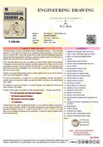
Telephone: (02692) 256237, Fax: (02692) 240089, e-mail: charotar@cphbooks.
com, Website: www.cphbooks.com. ENGINEERING DRAWING. By. N. D. Bhatt.
4.3.9 How to Draw an Octagon (8 Sides)⦠...... Draw a regular octagon inscribing a circle of diameter 80mm. ...... A plan of a house 12 cm represents 240 m.
J.Price Engineering Syllabus Page 1 of 5. 09/03/2013. Semester Course Title
CAD Skill .... UG Nx: Learning to work with the part navigator. Lau Chapter 2, 3. 3.
Using Solid Edge Version 17. By Jerry Craig. SDC ... Images from Solid Edge
Gallery. Page 2. Visit our website to learn more about this and other books: ...
To equip students with basic skills required in engineering drawings, ..... etc) are
very rarely used for technical drawings. The A-Format Paper Sizes. NOTES: (i) ....
necessary to completely describe the object are very roughly drawn (free hand).
(II) Internal choice has been given in question of Machine Drawing. ... Draw to
scale 1 : 1, the Front View of the assembly of a SQUARE HEAD BOLT(Across.
The GSFC Engineering Drawing Standards Manual is the official source for the ...
The Mechanical Engineering Branch, Mechanical Systems Division, has been ...
ENGINEERING MECHANICS. AND DRAWING. (Electrical Machines and
Appliances). Theory - II. VOCATIONAL EDUCATION. Higher Secondary - First
Year.
PRINT READING FOR DRAFTING & ENGINEERING DRAWING. Table of
Contents. INTRODUCTION. 1. BASIC DRAFTING CONCEPTS. Exercise 1:
Identify the ...
Print Reading
for Drafting & Engineering Drawing
Paul Ross Wallach 82071
PRINT READING FOR DRAFTING & ENGINEERING DRAWING
Table of Contents INTRODUCTION
1
BASIC DRAFTING CONCEPTS Exercise 1: Identify the drawing type Exercise 2: Identify the drawing type Exercise 3: Identify the drawing type Exercise 4: Identify the drawing type Exercise 5: Identify the drawing type Exercise 6: Identify the drawing type Exercise 7: Identify the drawing type Exercise 8: Identify the drawing type Exercise 9: Identify the drawing type Exercise 10: Identify the drawing type Exercise 11: Sectional drawings Exercise 12: Geometric terms


![[PDF] Download Print Reading for Engineering and ... - Google Sites](https://m.moam.info/img/260x300/pdf-download-print-reading-for-engineering-and-goo_6477b7f6097c474e708c03ea.jpg)


![[PDF] Print Reading for Engineering and Manufacturing ... - Google Sites](https://m.moam.info/img/260x300/pdf-print-reading-for-engineering-and-manufacturin_64780040097c4796708c535c.jpg)
![[PDF] Print Reading for Engineering and Manufacturing ... - Google Sites](https://m.moam.info/img/260x300/pdf-print-reading-for-engineering-and-manufacturin_64776f3b097c474b228c1228.jpg)
![[PDF] Download Print Reading for Engineering and ... - Google Sites](https://m.moam.info/img/260x300/pdf-download-print-reading-for-engineering-and-goo_6477ea46097c474e708c3bc7.jpg)
![[PDF] Print Reading for Engineering and Manufacturing Technology ...](https://m.moam.info/img/260x300/pdf-print-reading-for-engineering-and-manufacturin_6477eb18097c4796708c3c0a.jpg)

![[Ebook] Print Reading for Engineering and ... - Google Sites](https://m.moam.info/img/260x300/ebook-print-reading-for-engineering-and-google-sit_64788f72097c4744708cf7c3.jpg)
![[PDF] Print Reading for Engineering and Manufacturing ... - Google Sites](https://m.moam.info/img/260x300/pdf-print-reading-for-engineering-and-manufacturin_6477379f097c474b228bd3e0.jpg)
![Tekla Xsteel drawing - G [11] - Xtech Drafting](https://m.moam.info/img/260x300/tekla-xsteel-drawing-g-11-xtech-drafting_5a1b582a1723dd50c65a574e.jpg)