A.J. Han Vinck
. University of Duisburg-Essen,
Germany. Abstract- We describe coding and modulation aspects for a channel
with ...
Coding for a Terrible Channel A.J. Han Vinck
[email protected] University of Duisburg-Essen, Germany Abstract- We describe coding and modulation aspects for a channel with different kinds of a-typical noise disturbances. An example of such a channel is the powerline communication (PLC) channel, but the same noise disturbances can be observed in for instance xDSL communications. The channel is assumed to suffer from background noise, impulsive noise, narrowband noise and fading. In addition, in PLC, the signal attenuation can go up to 100dB/Km. This causes a problem for distances of the order of 100m-1000m. We concentrate on M-FSK as a modulation technique and look at the coding aspects that follow from this choice. Index terms-impulsive noise, narrowband noise, M-FSK modulation, Reed-Solomon codes, Powerline Communications
I.
INTRODUCTION
We consider communication channels that suffer from several disturbances like background noise, impulsive noise, narrowband noise and fading, simultaneously. Frequency disturbances like narrowband noise are permanent over a long period of time and of great importance in communication systems. On the other hand, impulse noise may put energy in larger parts of the spectrum in use for a short period. Impulsive noise can also have a periodic character. Constant envelope signal modulation, such as M-ary FSK, allows a transmitter's power amplifier to operate at or near saturation levels. The combination of M-ary FSK modulation and coding can provide for a constant envelope modulation signal, frequency spreading to avoid bad parts of the frequency spectrum, and time spreading to facilitate correction of frequency disturbances and impulse noise simultaneously. For robust communication, we assume non-coherent envelope detection. The M detected envelopes can be used in the decoding process in several ways. Hard decision, with only the best output or soft(er) decision with a multi valued output, see [1]. A simple soft decision detector uses a threshold T for every envelope detector. For values above the threshold we output a 1, otherwise a 0. Instead of a single demodulator output we then have M binary outputs per transmitted symbol. We consider two types of coding, Permutation Coding as block or trellis code and Reed-Solomon Coding. II.
PERMUTATION CODES
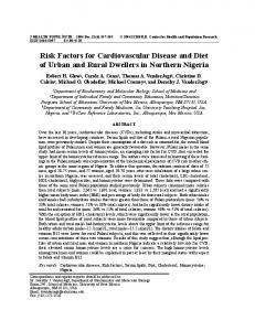
We first describe the effect of the different types of noise on the detector output. Definition 1: A permutation code C consists of |C| codewords of length M, where every codeword contains the M different integers 1,2,…,M as symbols. Some code constructions for block codes with dmin > 2, can be found in e.g. [3]. In [7] we give a code construction based on Reed-Muller codes. In [4 ,5] we report on permutation trellis codes. The effect of the different kinds of noise on the multi valued detector output can be seen from Fig. 1. We assume that M = 4 and transmit the codeword (1,2,3,4) as frequencies (f1, f2, f3, f4).
freq.
1000 0100 0010 0001 no noise
1010 1000 0100 0000 0010 0010 0001 0001 background noise
1001 0101 0011 0001 broadband
1111 0100 0010 0001 narrowband
1000 0 0 00 0010 0001 fading
time
Fig. 1. Several types of noise in the channel. The trellis permutation code construction principle, using a distance conserving mapping technique, can be explained by referring to Fig. 2.
Info
k-tuples
Convolutional encoder
mapping table n-tuples
permutation code symbols M-tuples
Fig. 2. Encoding for a permutation trellis code. The mapping table in Fig. 2 maps the output binary n-tuple code symbols from a R = k/n convolutional code into integer Mtuples, which are codewords from a permutation code. The key idea is to find an ordered subset of 2n M-tuples, out of the full set of permutation M-tuples (with cardinality M!), such that the Hamming distance between any two permutation M-tuples is at least as large as the distance between the corresponding convolutional code's output n-tuples which are mapped onto them. This property is called distance conserving, since the Hamming distance of the code is at least conserved, and may sometimes even be increased in the resulting trellis code.
Fig. 3. Example of the mapping (a) original code, (b) permutation trellis code. In [4] we give numerous examples of constructions, their basic properties and simulation results. The property of distance conserving can be easily verified. Briefly, let dij be the Hamming distance between the binary code symbols i and j, where 0 ≤ i, j ≤ 2n − 1. The key to the mapping technique is then to find an ordered subset of 2n permutation M-tuples such that eij ≥ dij, for all i ≠ j, where eij is the Hamming distance between the ith and jth M-tuple in the subset. Definition 2: A distance c increasing mapping, DIM+c, guarantees that: eij ≥ dij + c, for all i ≠ j. Remark: Obviously, to obtain a DIM+c, we need n + c ≤ M. Example: For n = 2, c = 1, we thus need M = 3. Any mapping will at least be distance conserving, since max{dij} = 2, while for permutation block codes min{eij} = dmin = 2. Several distance increasing maps can easily be found by inspection. For M = 3, {00, 01, 10, 11}⇒ { 231, 213, 132, 123 } . Example: For M = 4, many different mappings can be found by tree search. We present the following distance conserving map, using 16 out of the possible 24 permutation codewords, as an example:
0000, 0001, 0010, 0011
1234, 1243, 1342, 1342
0100, 0101, 0110, 0111 1000, 1001, 1010, 1011 1100, 1101, 1110, 1111
1423, 1432, 2134, 2143
⇒
. 3214, 3241, 2314, 2341 3421, 3412, 3124, 3142
For larger values of M, we can use some map for M = 4 as a core mapping or "kernel", and easily extend it recursively. This recursion can be briefly explained by example.
Example: The DIM+1, for n = 2 looks like {00, 01, 10, 11}⇒ { 231, 213, 132, 123 }. For n = 3 the DIM+1 is then constructed as: {000,001,010,011}⇒ {4231,4213,4132,4123};
{100,101,110,111}⇒ {1234,1243,1432,1423}.
It is easy to see how to generalize the extension method. In general, if the original map is DIM+1, then the new map has the same property. The second technique to construct DIM+c mappings uses the concept of Reed Solomon (RS) codes. Suppose that we generate codewords C of a (2, M)-RS code with minimum distance M-1, i.e.
( m1 , m2 )
1 1 ••• 0 1 •••
1 M-1
= c.
If we exclude the value m2 = 0, the codewords can be divided into M-1 groups of M codewords. Within every group the distance is M. Otherwise the distance is at least M-1. Suppose that we want to construct a mapping DIM+c, for binary vectors of length n. The construction can be described as follows: 1. Construct the M-1 sets of M codewords for M = n +c; 2. Assign two binary vectors with distance n to two M tuples of the same set (with distance M = n+c); 3. If all binary vectors are assigned, the mapping is DIM+c. Note that the above construction can be made for values of M that are prime, or power of a prime. For other values, we have to rely on specific constructions. This is the case for M = 6. Example: DIM+1. Let M = 3, The assignment for n = 2 can be made as follows: 00 11
012 120 201
01 10
021 102 210
Example: DIM+2. For M = 6 there is no RS code. We use the distance 5 construction from Klöve. This construction has 18 codewords, which is the maximum possible. We can assign 8 pairs of length n = 4 and thus construct a DIM+2. Example: DIM+3. For n = 7, we need M = 10. There is no RS code and no construction for distance M-1 available. However, for M = 9, distance 8, n = 6, we have a RS code with 72 codewords and thus a DIM+3 can be constructed. Example: DIM+2. For n = 6, we have 64 binary vectors. The RS code for M = 8, distance 7 has only 56 codewords. III. REED SOLOMON CODES
The second type of codes that can be useful are the Reed Solomon (RS) codes. We will investigate the effect of several types of noise on the decoding performance. Among the sources of the narrowband noise are TV vertical scanning frequency 15.625 kHz and its harmonics, timecodes transmission frequencies such as 77.5 kHz and AM transmissions. Other sources are emergency services, radio amateurs, etc. Narrow band noise may cause an envelope detector output to be equal to 1 during many time instants. If the error correcting code that is used is a Reed-Solomon code, then this type of error may cause many erasure symbols for the RS decoder. This is caused by the fact that the constant symbol codeword is a valid codeword. The generator matrix usually looks like:
CRS = .
1 1 1 1 α α2 1 α2 α4 …
… … …
1 αn-1 α2(n-1)
1 αk-1 α2(k-1)
...
α(k-1)(n-1)
Note, that in this chapter the parameter n is used for the length of the RS code. We look at a special class of RS codes, with minimum distance n-k+1, defined by:
C=
1 α α2 … 1 α2 α4 … … 1 αk α2k ...
αn-1 α2(n-1) αk(n-1)
.
The defined RS code C has the following properties: 1. 2. 3.
the all zero codeword is the only codeword with n symbols that are the same all other codewords contain a maximum of k symbols that are the same all other codewords contain at least n/k different symbols
If an envelope is detected to be 1 during a long period of time, we assume that a narrow band disturbance occurred. We reset this output to be 0, unless this output belonged to the all zero codeword of length n, or if the output symbol is the only output with value 1. In the latter case, the transmitted symbol coincided with the narrow band disturbance. We reported on the measurements at the ISPLC2005 in Vancouver, Canada, [9]. If knowledge about the narrowband interference is present at the encoder, we may use a method that can be derived from [6]. This method simply avoids certain RS symbols to occur in the output. There is a reduction in minimum distance, but the method is simple to use and can be extended to exclude a particular set of symbols. This knowledge can then be used to update the output of the envelope detector. In Fig. 4 we give the parameters of the RS code that are of importance for the description. ( info control ) k r
100 …0 x x … x 0100 0 x x … x … … 00… 01 x x … x k+r
= CS
n-(k+r)
Fig. 4. Systematic RS-encoding. The k q-ary information symbols are precoded such that they do not contain a particular set A of symbols. A has cardinality A. The r control bits are used to avoid symbols from A to occur in the check part. The number of control vectors we can choose is (q-A)r. If the number of ways to choose a forbidden symbol in the check part is less than (q-A)r we can always find a particular choice for the control vectors that realizes an output without the undesired symbols. This is true for (n-(k+r)) (q-A)r-1 A < r (q-A) or A < q/(n-(k+r)). Note that for A = 1, r = 1, q = n+1 (RS!), the condition is always fulfilled. However, the minimum distance is reduced by 1. Impulsive noise results mainly from switching transients and is characterized by its duration, amplitude and the inter-arrival time. We assume that impulsive noise causes all outputs of the envelope detectors to be equal to 1. This type of error is recognized as an erasure at the RS decoder. Background noise is always present in the power line channel. It is modeled by a Gaussian probability density function and is colored with a power spectral density decreasing with a slope of 20-30 dB/decade within the CENELEC band (up to 150 kHz). Background noise may cause symbol errors (one output changed from 1 to 0 and another changed from 0 to 1) or erasures (one output changes from 1 to 0 or one output changes from 0 to 1). For the background noise, with assumed constant noise power density we can give an estimate of the detection error probability in the uncoded situation as
Pe ≤
E log2 M ln 2− b 2 N0 e ,
where Eb is the energy per transmitted information bit, see [8]. If we use a permutation code with minimum distance dmin, the coded error probability can be estimated as
Pe
d E log 2 | C| ln 2 − min b 2 MN 0 ≤e ,
where we used the fact that for a permutation code of length M, M Es = log2|C| Eb. The cardinality for permutation codes is upper bounded as | C |≤
M! . (d min −1)!
Assuming equality, for dmin = M – a, where a is a constant, we have for large values of M
lim M → ∞ Pe
E a log 2 M ln 2 − b 2N 0 ≤e ,
which shows that coding gives a great improvement in the error exponent.
Fig. 5. Example of Impulse noise from Pierre Degauque et. al., Univ. of Lille, COST 261 project In frequency selective fading, some frequencies may be in deep fade. As a consequence, the particular detector output will be 0 for a long time, if threshold detection is used ( assuming that this is the only disturbance). For RS codes, transmitting the non-0 codeword, this means that a maximum of k erasures occurs. ( a maximum of k symbols are the same in a codeword). As an alternative, we can also reset these positions to be 1. If we transmit the all-0 codeword and we detect the corresponding n outputs to be 0 we may conclude that the all-0 codeword has been transmitted. The RS decoder can also be modified to correct a limited number of additional errors caused by the other types of noise.
|H(f)|
-20 -40 -60 -80 dB 0
5
10
15
20
MHz
Fig. 6. Transfer function from Dostert, ISPLC2005, Vancouver, Canada For permutation codes, the effect of the above type of disturbances is easy to describe. All types of disturbances interfere with a permutation codeword in only one position. The permutation codeword contains the particular symbol only once and so do all other codewords in the permutation code. Hence, if less than dmin disturbances occur within a codeword, the decoder using minimum distance decoding can find the correct codeword. Simulation results can be found in [2].
For permutation trellis codes the situation is more complex. Narrowband noise and fading may cause an error in many sections of the trellis. The concept of distance increased mapping reduces this effect.
Table 1 Examples of ETSI radio frequencies up to 30 MHz
190-405 KHz 518 kHz 14 Mhz 25 Mhz 27 MHz
Radio Navigation NAVTEX Amateur Radio astronomy CB IV. CONCLUSIONS
We describe the combination of MFSK and coding. Two types of codes are used: RS codes and Permutation codes. Both types of codes are using the outputs of M envelope detectors in a particular way. This allows efficient correction of errors and erasures caused by impulsive noise, narrow band noise, background noise and frequency selective fading. ACKNOWLEDGEMENT
This research has been carried out in cooperation with the group of Professor Hendrik Ferreira, Rand Afrikaanse Universiteit, Johannesburg, South Africa. REFERENCES
[1] A.J. Viterbi, “A rubust ratio-threshold technique to mitigate tone and partial band jamming in coded MFSK systems,” in Proc. 1982 IEEE MILCOM, Boston, MA, USA, Oct. 17-20, 1982, pp. 22.4.1-22.4.5. [2] Kenneth W. Shum, „Permutation Coding and MFSK Modulation for Frequency Selective Channel,” PIMRC 2002. [3] I.F. Blake, "Permutation codes for discrete channels," IEEE Transactions on Information Theory, vol. 20, no. 1, January 1974, pp 138-140. [4] H.C. Ferreira, A.J. Han Vinck, Th.Swart and I. de Beer, “Permutation Trellis Codes,” accepted for publication in the IEEE Trans. On Communications. [5] H.C. Ferreira and A.J. Han Vinck,”Interference Cancellation with Permutation Trellis Codes,” Proc. IEEE Veh. Techn. Conference Fall 2000, Boston, pp. 2401-2407. [6] G. Solomon, “A Note on Alphabet Codes and Fields of Computation,” Information and Control, 1974, pp. 395-398. [7] Tadashi Wadayama and A.J. Han Vinck, “A Multilevel Construction of Permutation Codes,” IEICE Transactions on Fundamentals, October 2001, pp. 2518-2522. [8] S. Haykin, Communication Systems, Wiley, 3rd edition, p. 554. [9] Jaco Versfeld and A.J. Han Vinck, “Reed-Solomon Coding to Enhance the reliability of M-FSK in a Power Line Environment,” 9th International Symposium on Power-Line Communications and Its Applications, Vancouver, April 6-8, 2005, , pp.100-104, ISBN 0-7803-8844-5