Prioritized Random Access for Machine-to-Machine Communications in OFDMA Based Systems Taehoon Kim, Kab Seok Ko, and Dan Keun Sung Department of Electrical Engineering, KAIST, Daejeon 305-701, Korea Email: {thkim, ksko}@cnr.kaist.ac.kr,
[email protected]
Abstract—In machine-to-machine (M2M) communications, machine nodes perform a random access (RA) to synchronize with the eNodeB in order to transmit their new packets. However, the conventional RA cannot support prioritized accesses during the RA procedure, even though there are a variety of classes with different quality-of-service (QoS). In this paper, we propose a prioritized random access (PRA) scheme, which enables machine nodes to indicate their access priority during the access phase by differentiating their transmission power level. Moreover, we thoroughly analyze the PRA scheme in terms of collision probability and access delay. The performance evaluation shows that the PRA scheme enables the nodes to indicate the access priority according to their QoS during the RA procedure as well as to achieve much lower collision probabilities and shorter access delay. Index Terms—Machine-to-Machine, random access, access priority, fixed-location, timing alignment
I. I NTRODUCTION Machine-to-machine (M2M) communications or machinetype communications (MTC) refer to the communication between M2M servers and machine nodes or among the machine nodes, without human intervention [1]. Recently, they have attracted great attention due to their highly promising market potential and a wide range of their applications such as smart metering, emergency alarm, surveillance, and e-health [2]. As a result, there have been a number of studies including M2M communications in cellular networks [3], [4]. In cellular networks, an RA is used for initial uplink access to connect and synchronize with the eNodeB. Since data transmission is not performed in this procedure, the RA in the cellular networks does not consider the QoS guaranteeing of different services during access phase [5]. As a result, it is hard for nodes to indicate their priority during access phase. However, after a connection is made with the eNodeB through the RA, the node can indicate its QoS and request the required amount of time-frequency resources for communication [6]. In other words, the node can request its QoS during resource allocation after the completion of the RA procedure. In M2M communications, however, there exist an extremely large number of nodes that attempt RAs. In this case, a severe physical random access channel (PRACH) overload problem may occur, as a result, it is even hard to access the networks. The nodes suffer considerable time to access the networks, and, thus, even a given resource management scheme cannot
guarantee acceptable end-to-end delay according to their QoS. Therefore, with the conventional method, there are limitations in supporting different QoS in M2M communications. Rivero-Angeles et al. [7] investigated a prioritization mechanism for RA strategies in cellular networks using different retransmission probabilities depending on the priorities of nodes, as a result, this can be classified into the access class barring (ACB) scheme [4]. Although high-priority nodes have a high probability of success in their RA quickly using the retransmission probabilities determined by the eNodeB, however, the nodes still cannot express their own access priority during the access phase. In addition, other access control schemes such as a PRACH resource separation scheme, a dynamic PRACH resource allocation scheme, and a pullbased scheme were suggested [4], however, these are not fundamental solutions to enable the nodes to indicate their own access priority during the access phase. Therefore, it is much better to think of a new paradigm that a node can represent its own access priority during the RA procedure. However, little attention has been given to access priority during the access phase in cellular networks. Kim et al. [8] proposed a new RA scheme to support emergency alarms during the access phase, however, it is applicable only to emergency situations. Therefore, we need to investigate a more generalized RA scheme to support access priority during the access phase. In this paper, we propose a prioritized random access (PRA) scheme in order to guarantee access priority during the RA procedure. Moreover, we thoroughly analyze the PRA scheme in terms of collision probability and access delay. Finally, we show that the PRA scheme enables the nodes to indicate the access priority according to their QoS during the RA procedure as well as to achieve much lower collision probabilities and shorter access delay. The rest of this paper is organized as follows. In Section II, we review the conventional RA scheme in LTE/LTE-A. In Section III, we describe a system model and the proposed prioritized random access (PRA) scheme. In Section IV, we numerically analyze the collision probability and average access delay of the PRA scheme. In Section V, we compare the PRA scheme with the conventional RA scheme. Finally, we draw conclusions in Section VI.
Machine Node 1) Preamble Tx
Machine nodes in the 1st group region
R
eNodeB
Check a high-level detection threshold
Machine nodes in the 2nd group region
d
...
High priority request? Machine nodes in the last group region
Find the used preambles and make HIGH-priority set
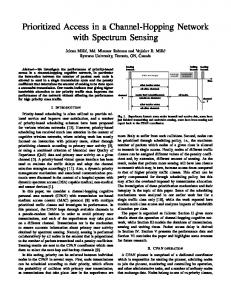
Fig. 1. System model: Cell radius is R[m] and cell is spatially separated into multiple group regions.
Make an RAR message using the preamble indices in HIGH-priority set
II. A C ONVENTIONAL R ANDOM ACCESS S CHEME The conventional RA procedure of LTE/LTE-A system consists of 4 steps [9]. In the first step, a node randomly selects one preamble among Np orthogonal preambles and transmits the selected preamble to the eNodeB via the PRACH. In the second step, if there exists a detected preamble, then the eNodeB sends an RA response (RAR) message via the Physical Downlink Control Channel (PDCCH). The RAR message includes the timing alignment (TA) information, uplink grant, and the cell-radio network temporary identifier (C-RNTI). If there are more than two nodes that send an identical preamble in the first step, they receive the same RAR message. In this case, they utilize the same resource for the third step, and, thus, this causes a collision eventually. In the third step, the node transmits its C-RNTI as an identifier and a scheduled message on the Physical Uplink Shared Channel (PUSCH) assigned in the second step. Once the message is transmitted, the node starts a contention resolution (CR) timer for determining whether a collision occurs or not. In the fourth step, the eNodeB echoes the identities of the nodes, which successfully transmit its message in the third step, on the Physical Downlink Shared Channel (PDSCH). If the node does not receive any messages within the CR timer, then it regards the RA as a failure and retries the RA after performing a backoff mechanism. Otherwise, it regards the RA as a success. III. S YSTEM M ODEL A. System Environment Fig. 1 shows the system environment. We consider a single cell with radius R. In a cell, N + 1 fixed-location machine nodes are uniformly distributed, whose TA value is assumed to be unchanged. The TA value is required to synchronize with the eNodeB for uplink transmissions, and it represents the propagation delay from the node to the eNodeB. When the TA value is carried on the RAR message, it is quantized and takes the index value as an integer multiple of 16Ts , where Ts is the basic time unit in LTE system [10]. Accordingly, the coverage of the cell can be spatially partitioned into multiple group regions based on the TA values. Although the nodes in the same group region have different propagation delays, they have the same TA value due to the quantization. The gth group region represents the area that the distance from the eNodeB belongs to ( (g − 1)d, gd ], where d = 16Ts · c and c is the speed of light, and the nodes located in this area have the same TA value with g − 1. We assume that the fixed-location machine nodes acquire and store their TA values during the initial access via the
NO
Check a low-level detection threshold Low priority request? Backoff
Find the used preambles which are not in HIGHpriority set and make LOWpriority set
NO
Make an RAR message using the preamble indices in LOW-priority set
NO
2) RAR message Tx 3) Timing Alignment Matching 4) Scheduled Tx 5) Contention Resolution
Fig. 2.
Random access procedure of the proposed PRA scheme
conventional RA. We also consider two access priorities: a high-priority access and a low-priority access. B. A Prioritized Random Access Scheme Fig. 2 shows the procedure of the PRA scheme. Since we consider fixed-location machine nodes, a prioritized random access (PRA) scheme is also composed of 5 steps, where the ‘TA matching step’ is also included [11]. The first and the second steps are ‘preamble transmission’ and ‘RAR message transmission’, respectively. In the first step, a node randomly selects one preamble among Np orthogonal preambles and transmits it to the eNodeB. In this step, when the node transmits the selected preamble, the node additionally selects the transmit power level according to the access priority in order to target different detection thresholds. After the first step, the eNodeB receives the aggregated signal via PRACH and detects which preamble indices are used in the first step. During the detection procedure, the eNodeB follows two steps. First, the eNodeB uses the high-level detection threshold in order to detect the high-priority preamble indices, and makes RAR messages using the detection results. Second, the eNodeB uses the low-level detection threshold in order to detect the low-priority preamble indices, and makes the remaining RAR messages using the detection results. However, when the eNodeB finds the low-priority preamble indices, it excludes the preamble indices which are used for high-priority. Due to the exclusion, the RAR messages are likely to be made with preamble indices and the corresponding TA values of the nodes which attempt the high-priority access. The third step is ‘TA matching’, where each node compares the stored TA value with a TA value which is contained in the received
RAR message. If the received TA value matches with the stored one, the node proceeds the RA procedure to the next step. If the received TA value does not match with the stored one, the node immediately starts a back-off mechanism with a randomly selected value among [0, W -1], where W is a backoff indicator (BI). Here, we call the collision detected in the TA matching step a soft-collision. Due to the TA matching step, each node pre-determines whether a collision in the remaining steps occurs or not. If so, they abort their remaining steps, as a result, other nodes may improve their success probability of the remaining steps. The fourth and the fifth steps are ‘scheduled transmission’ and ‘contention resolution’, respectively. If there are more than two node that use the same resource in the fourth step, a collision occurs here, and the nodes with the collision start a back-off mechanism with a randomly selected value among [0, W -1] after their CR timer expire. Here, we call the collision detected after the CR timer expires a hard-collision.
TA value : 0
x1 , p1
…
•
•
E is a random variable that represents the existence of other nodes in the same spatial group region that transmit the same preamble that the tagged node uses. In other words, if there is any node that uses the same preamble and has the same TA value at the same time, E is set to 1. Otherwise, E is set to 0. D is a random variable that represents whether the TA value of the tagged node is included in the RAR messages or not. In other words, if the eNodeB detects the same preamble with the same TA value, D is set to 1. Otherwise, if the eNodeB detects the same preamble with the different TA value, D is set to 0. G is a random variable that represents whether the tagged node is in the g-th spatial group region. In other words, if the node belongs to the g-th spatial group, G is set to g, and its probability can be expressed as: Pr{G = g} = Pr {(g − 1)d < r ≤ gd} ∫ gd (2g − 1)d2 ∆ µ(r)dr = = ug , = R2 (g−1)d
•
(1)
where µ(r) is the probability density function (PDF) that a particular node is at the distance r from the eNodeB, 2r and it can be expressed as R 2 , since we assume that the nodes are uniformly distributed. P is a random variable that represents the access priority of the tagged node. If the access priority is high, P is set to 1. Otherwise, P is set to 0.
Given G and P , according to E and D , we can categorize the preamble conditions of the tagged node into four cases:
… Low-level detection threshold
x2 , p2
x4 , p4
Preamble index
the m-th preamble
Fig. 3. The preamble status of all nodes when N is assumed to 4 (x = [0, 0, 1, 1, 2]): The tagged node in the first group region attempts a highpriority RA by using the m-th preamble, which is represented by the dashed line with a square mark •
•
A. Parameters and Events
•
x5 , p5
High-level detection threshold
IV. N UMERICAL A NALYSIS
We define random variables to analyze the collision probability and the average access delay described in the following subsections: Subsection IV-B and Subsection IV-C.
x3 , p3
•
•
No collision, but undetected (E = 0, D = 0) : The selected preamble is used by other node(s) in different spatial group regions, and the eNodeB detects the preamble with a different TA value. This results in a softcollision. Success (E = 0, D = 1) : The selected preamble is not used by any other node in the same spatial group region and is used by other node(s) in different spatial group regions, simultaneously, however, the eNodeB detects the preamble of the tagged node. Another case is that the selected preamble is not used by any other node at all. Collision, but undetected (E = 1, D = 0) : The selected preamble is used by other node(s) in the same spatial group region and other node(s) in different spatial group regions, simultaneously, and the eNodeB detects the preamble with one of different TA values. This also results in a soft-collision. Detected, but collision (E = 1, D = 1) : The selected preamble is also used by other nodes in the same spatial group region, and the eNodeB detects the preamble with the same TA value. This results in a hard-collision.
B. Collision probability We analyze the collision probability under the assumption that the number of other nodes is N . In order to describe the preamble status of the other nodes from the viewpoint of one tagged node, we use a multinomial distribution. Moreover, in order to describe the collision in more detail, we divide the collision into two types of collisions: a soft-collision and a hard-collision. Fig. 3 shows an example of the possible preamble status, and there are 5 cases where the preambles can be classified. As a result, the probability mass function (PMF) of the multinomial distribution is ∑5 5 Γ( xi + 1) ∏ xi f (x; p) = ∏5 i=1 pi , (2) i=1 Γ(xi + 1) i=1 where Γ(·) is a gamma function, x = [x1 , x∑ 2 , x3 , x4 , x5 ], ∑5 5 p = [p1 , p2 , p3 , p4 , p5 ], x = N , and i=1 i i=1 pi = 1. x1 (x2 ) represents the number of nodes attempting high(low)priority access with the same preamble in the same spatial group region, compared with the tagged node. Likewise, x3 (x4 ) represents the number of nodes attempting high(low)priority access with the same preamble in different spatial
group regions, compared with the tagged node. x5 represents the number of nodes using different preambles, compared with the tagged node. p1 , p2 , p3 , p4 and p5 are the corresponding probabilities, respectively. Therefore, p can be expressed as: p = [p1 , p2 , p3 , p4 , p5 ] (3) ug phigh ug plow (1 − ug )phigh (1 − ug )plow 1 =[ , , , , 1− ], Np Np Np Np Np where phigh and plow represent the portion of high- and lowpriority nodes, respectively. The collision probability of the tagged machine node can be calculated by dividing the collision into two parts: (i) a softcollision and (ii) a hard-collision. If a tagged machine node belonging to the g-th spatial group region attempts a highpriority RA, the soft-collision probability can be expressed as: ∑1 psc|G,high = Pr {E = e , D = 0|G = g, P = 1} e=0
−x1 N −x −x2 −x3 N N∑ 1 −x2 N −x1 ∑ ∑ ∑
=
x1 =1 x2 =0
x3 =1
x1 =0 x2 =0
x3 =1
x3 x1 + x3 + 1
f (x; p) ·
x3 x3 + 1
x4 =0
−x1 N −x −x2 −x3 0 N∑ 1 −x2 N −x1 ∑ ∑ ∑
+
f (x; p) ·
x4 =0
(4)
and the hard-collision probability can be expressed as: phc|G,high = Pr {E = 1 , D = 1|G = g, P = 1} −x1 N −x −x2 −x3 N N∑ 1 −x2 N −x1 ∑ ∑ ∑
=
x1 =1 x2 =0
x3 =0
x1 =0 x2 =1
x3 =0
x1 + 1 x1 + x3 + 1
f (x; p) ·
1 . x3 + 1
x4 =0
−x1 N −x −x2 −x3 0 N∑ 1 −x2 N −x1 ∑ ∑ ∑
+
f (x; p) ·
x4 =0
(5)
Finally, the soft- and hard-collision probabilities of the node attempting a high-priority access are expressed as: ∑gmax psc,high = psc|G,high · ug , (6) g=1
and phc,high =
∑gmax g=1
phc|G,high · ug ,
(7)
respectively, where gmax is the total number of spatial group regions and it can be represented as gmax = ⌈R/d⌉. Likewise, if a tagged machine node belonging to the g-th spatial group region attempts a low-priority random access, the soft-collision probability can be expressed as: ∑1 psc|G,low = Pr {E = e , D = 0|G = g, P = 0} e=0
=
−x1 N −x −x2 −x3 N N∑ 1 −x2 N −x1 ∑ ∑ ∑ x1 =0 x2 =0
+
−x1 0 N∑ ∑
x3 =1
+
0 ∑
0 ∑
x4 =0
−x2 −x3 0 N −x1∑ ∑
x1 =0 x2 =1 x3 =0
f (x; p) ·
x4 =0
−x2 −x3 0 N −x1∑ ∑
x1 =0 x2 =0 x3 =0
f (x; p) ·
x4 =0
f (x; p) ·
x3 x1 + x3
x4 x2 + x4 + 1 x4 x4 + 1
(8)
and the hard-collision probability can be expressed as: phc|G,low = Pr {E = 1 , D = 1|G = g, P = 0} =
−x1 N −x −x2 −x3 N N∑ 1 −x2 N −x1 ∑ ∑ ∑ x1 =1 x2 =0
+
−x1 0 N∑ ∑
x3 =0
x4 =0
−x2 −x3 0 N −x1∑ ∑
x1 =0 x2 =1 x3 =0
f (x; p) ·
f (x; p) ·
x4 =0
x1 x1 + x3
x2 + 1 . (9) x2 + x4 + 1
Thus, the soft- and hard-collision probabilities of the node attempting a low-priority access, psc,low and phc,low can be calculated similarly with Eq.(6) and Eq.(7), respectively. C. Average access delay Access delay is defined as the time between a new packet generation and successful completion of the RA procedure. In order to calculate the average access delay, we adopt an analytical framework using a Markov chain proposed in [8]. We analyze the average access delay under the assumption that the PRACH period and back-off indicator are given by 10(ms) and 20(ms) [9], respectively. The state is defined here as the number of RA opportunities (RAOs) that a node encounters upon generation of a new packet, and, thus, the state space S can be defined as S = {0, 1, 2, · · · , i, · · · , M, F }. M represents the maximal number of RAOs that a node may attempt the RA and F indicates the success state (or final state) as an absorbing state. If the node succeeds in the RA at any state, the state has a transition to state F . ni represents the number of contending nodes at state i, that is, at the i-th RAO. ni is determined by the number of nodes that generate a new packet and the number of nodes that come from the previous RA slots due to the collisions. Thus, ni can be derived as: ∑i−1 ∑i−1 ni = Asc,j + Ahc,j + Ai , (10) j=1
j=1
where Asc,j = nj · [phigh plow ] · [pjsc,high pjsc,low ]T · g(i − j), Ahc,j = nj · [phigh plow ] · [pjhc,high pjhc,low ]T · h(i − j), and Ai = TRACH ·λ·N , where TRACH and λ represent the PRACH period and packet arrival rate, respectively. pjsc,high (pjsc,low ) and pjhc,high (pjhc,low ) represent the soft- and high-collision probabilities of the high(low)-priority nodes at state j, where the number of nodes is given by nj . g(x) and h(x) represent the probability that the node retries the RA after x RAO(s) when the soft- and hard-collision occur, respectively. g(x) and 3 h(x) can be represented as g(x) = 20 ·δ(x−1)+ 10 20 ·δ(x−2)+ 7 5 10 5 ·δ(x−3) and h(x) = ·δ(x−1)+ ·δ(x−2)+ 20 20 20 20 ·δ(x−3) [8], [9], respectively, where δ(·) is a delta function. As a result, Asc,j and Ahc,j represent the number of nodes that fail in the previous RA at state j due to the soft-collision and the hardcollision, respectively, and reattempts the RA at state i. A state transition occurs whenever the node performs an RA. If the node succeeds in the RA at state i, then it transfers to state F . Otherwise, it has a transition to state j and reattempts an RA at state j. Since the collision probabilities
are different according to the access priority, we have to define the state transition probability differently according to the access priority. When the node attempts the k-priority access (k ∈ {high, low}), the state transition probability from state i to state j can be expressed as: 1 , if i = 0, j = 1 0 , if i = 0, j ̸= 1 pi · g (j − i) k sc,k (11) πi,j = +pihc,k · h (j − i) , if i ̸= 0, j > i 1 − pisc,k − pihc,k , if i ̸= 0, j = F 0 , otherwise , where k ∈ {high, low}. We can define the state transition k as an element of the i-th row and matrix Πk , which has πi,j the j-th column and it can be expressed as: k Πk = (πi,j ) , i, j ∈ S and k ∈ {high, low}.
(12)
Fig. 4 shows the state transition diagram, and all the state transition probabilities are calculated by using Eq. (11). Using the state transition matrix Πk , we can derive the n-step state transition matrix as Πnk . We can calculate the summation of Πnk for all n(1 ≤ n ≤ Q, where Q denotes the maximal number of trials), which is denoted by Λk and can be expressed as: [ ]T ∑Q T T T T T n k k k k k Λk = Πk = r0 r1 · · · ry · · · rM rF n=1 [ ] = ck0 ck1 · · · cky · · · ckM ckF , k ∈ {high, low}, (13) k k k k k · · · ry,i · · · ry,M ry,F ] is the y-th row ry,1 where ryk = [ry,0 k k k k vector of Λk and cy = [cy,0 cy,1 · · · cy,i · · · cky,M cky,F ] T is the y-th column vector of Λk . k Especially, r0,j represents the probability that the node (re)attempts the RA at state j, ckj,F represents the success probability of the RA at state j. Finally, we can derive the average access delay of the high- and low-priority RAs, Dhigh and Dlow , respectively.
Dk =
∑M j =1
k · ckj,F · dj , k ∈ {high, low} , r0,j
(14)
where dj represents the access delay if the node succeeds in k ·ckj,F ·dj represents the access delay the RA at state j, and r0,j if the node succeeds in the RA at state j. V. P ERFORMANCE E VALUATION A. Simulation Environments We perform simulations using a process-oriented discreteevent simulation package, CSIM. The simulation parameters are set based on reference [9] and they are listed in Table I. We assume that the location of nodes follows a uniform distribution and the RA inter-arrival time follows an exponential distribution. We also assume that a certain amount of preambles is reserved for M2M communications.
TABLE I S IMULATION
PARAMETERS AND VALUES
Parameters Cell radius (R) The number of machine nodes (N ) Packet arrival rate (λ) The number of preambles (Np ) PRACH period (TRACH ) Back-off Indicator (W ) ContentionResolution Timer Maximal number of trials (Q)
Values 2 (km) 5,000 ∼ 30,000 1/60, 1/120, 1/180, 1/300 (sec−1 ) 8, 15 10 (ms) 20 (ms) 48 (ms) 10
B. Simulation and Analytical Results In all figures, markers indicate the simulation results and lines indicate the analytical results. Fig. 5 shows the effect of the total number of machine nodes in a cell on the average access delay. The PRA scheme guarantees that the high-priority nodes have much shorter access delay than the low-priority nodes, and it also shows much lower access delay than the conventional RA regardless of the access priority. Especially, even though the contention becomes severer as the number of nodes increases, the PRA scheme enables the nodes to access the network stably. For example, in case of λ = 1/60 and Np = 8, the PRA scheme can support up to 30, 000 nodes guaranteeing their different access priority during the access phase. However, the conventional RA scheme only can support up to 15, 000 nodes, and it cannot provide any access priority. Fig. 6 shows the effect of the inter-arrival time of new packets on the average access delay. It shows a similar trend to that of Fig. 5. The PRA scheme effectively guarantees the access priority during the access phase even in harsh conditions, and it always shows shorter average access delay than the conventional RA scheme. For example, in case of N = 30, 000 and Np = 8, the PRA scheme can support up to λ = 1/60 with guaranteeing the access priority, however, the conventional RA only can support up to λ = 1/120 without supporting the access priority. Fig. 7 shows the average access delay for varying the portion of high-priority machine nodes, phigh , for N = 30, 000 and λ = 1/60. In the figure, we cannot deal with the conventional scheme for Np = 8, since the conventional scheme cannot guarantee the nodes to access the network with the average access delay in this extremely harsh condition. As phigh increases, the average access delay of high-priority nodes increases, since the contention among high-priority nodes becomes severer. The average access delay of low-priority nodes also more increases, since most of preamble indices are used by the nodes attempting the high-priority access, and, thus, the exclusion of low-priority preamble indices becomes more severer. In conclusion, the improved access delay of high-priority nodes can be achieved at the sacrifice of lowpriority nodes, therefore, the large increment of the access delay of high-priority nodes can be efficiently avoided.
k π 1,3 k π 0,1
0
k π 1,2
1
2
π k π 2,3
k 2,4
3
k π 2,8
k π 1,7
π k π 3,4
Soft-collision k k π 4,7 π 5,8
k π 3,6
k π 2,5
k π 1,4
k 3,5
π k π 4,5
4
...
k π 5,7
k 4,6
k π 5,6
5
6
...
k π 6,9
π k π 6,7
k 6,8
7
k π 7,10
π k π 7,8
k 7,9
8
9
...
M
...
k
k π 1,9
π 0,k F
k π 1,8
π 1,k F
k π π 2,10 2,9
π 2,k F
π Mk , F
Hard-collision
F
Fig. 4. 100
A state transition diagram of the Markov chain for TRACH = 10(ms), W = 20(ms), and k ∈ {high, low} 100
Np=8(conv) Np=15(conv)
90
90
80
Np=8(PRA,low−priority)
Average access delay[ms]
Average access delay[ms]
Np=8(PRA,high−priority) Np=15(PRA,high−priority)
70
Np=15(PRA,low−priority)
60 50
Np=15(PRA,low−priority)
50
30
30
1.5 2 The number of machine nodes (N)
2.5
3 4
x 10
Fig. 5. The effect of the number of machine nodes on the average access delay for λ = 1/60(sec−1 ) and [phigh , plow ] = [0.5, 0.5].
20 0.1
0.2 0.3 0.4 0.5 0.6 0.7 The portion of the high−priority machine nodes (p
0.8 )
0.9
high
Fig. 7. The effect of the portion of high-priority machine nodes on the average access delay for N = 30, 000 and λ = 1/60(sec−1 ).
communications.
100
ACKNOWLEDGMENT
Np=8(conv) Np=15(conv)
90
Np=8(PRA,high−priority) Np=8(PRA,low−priority)
80
Np=15(PRA,high−priority) 70
Np=15(PRA,low−priority)
60 50 40 30 20 50
Np=15(PRA,high−priority)
60
40
1
Np=8(PRA,high−priority) Np=8(PRA,low−priority)
70
40
20 0.5
Average access delay[ms]
80
Np=15(conv)
100
150 200 250 Inter−arrival time (1/λ) [sec]
300
350
Fig. 6. The effect of the inter-arrival time on the average access delay for N = 30, 000 and [phigh , plow ] = [0.5, 0.5].
VI. C ONCLUSIONS In this paper, we proposed a prioritized random access (PRA) scheme in order to guarantee access priority during the RA procedure. We thoroughly analyzed the PRA scheme in terms of the collision probability and access delay. The performance evaluation shows that the PRA scheme enables the machine nodes to indicate their access priority during the access procedure as well as to achieve much lower collision probabilities and shorter access delay. The PRA scheme supports the access priority efficiently although there are an extremely large number of machine nodes in M2M
This work was supported by the National Research Foundation of Korea(NRF) grant funded by the Korea government(MSIP) (No. 2014R1A2A2A01005192) R EFERENCES [1] R. Q. Hu, Y. Qian, H. Chen, and A. Jamalipour, “Recent Progress in Machine-to-Machine Communications,” IEEE Commun. Mag., 2011. [2] R. Liu, W. Wu, H. Zhu, D. Yang, “M2M-Oriented QoS Categorization in Cellular Network,” Proc. IEEE Wireless Communications, Networking and Mobile Computing (WiCOM), Sept. 2011. [3] Service Requirements for Machine-Type Communications, 3GPP TS 22.368 V10.1.0, June 2010. [4] RAN Improvements for Machine-type Communications, 3GPP TR 37.868 V11.1.0, Oct 2011. [5] S. Sesia, I. Toufik, and M. Baker, LTE-The UMTS Long Term Evolution:From Theory to Practice, Second Edition. WILEY, 2011. [6] F.R. Farrokhi, M. Olfat, M. Alasti, and K.J.R. Liu, “Scheduling algorithms for quality of service aware OFDMA wireless systems,” Proc. IEEE GLOBECOM, Dec. 2004. [7] M.E. Rivero-Angeles, D. Lara-Rodriguez, F.A. Cruz-Perez, “Differentiated Backoff Strategies for Prioritized Random Access Delay in Multiservice Cellular Networks,” IEEE Trans. Veh. Technol., Jan. 2009. [8] T. Kim, K. S. Ko, I. Bang, and D. K. Sung, “A Random Access Scheme Based on a Special Preamble for Supporting Emergency Alarms,” Proc. IEEE WCNC, 2014. [9] Evolved Universal Terrestrial Radio Access Network(E-UTRAN); Medium Access Control (MAC) protocol specification, 3GPP TS 36.321 V11.2.0, Mar 2013. [10] Evolved universal terrestrial radio access(E-UTRA) physical layer procedures, 3GPP TS 36.213 V11.3.0, June 2013. [11] K. S. Ko, M. J. Kim, K. Y. Bae, D. K. Sung, J. H. Kim, and J.Y. Ahn, “A Novel Random Access for Fixed-Location Machine-to-Machine Communications in OFDMA Based Systems,” IEEE Commun. Lett., vol. 16, no. 9, pp. 1428–1431, Sept. 2012.