Jiantao Pu Imaging Research Laboratory, The University of Pittsburgh, Pittsburgh, PA 15213 e-mail:
[email protected]
Karthik Ramani Purdue Research and Education Center for Information System in Engineering, Purdue University, West Lafayette, IN 47907 e-mail:
[email protected]
1
Priority-Based Geometric Constraint Satisfaction A well-constrained geometric system seldom occurs in practice, especially at the sketchbased initial conceptual design stage. Usually, it is either under- or overconstrained because design is a progressive process and it is difficult for a designer to specify all involved constraints in a consistent way. This paper presents a priority-based graphreduction solution, in which each constraint is assigned with a priority to guide the reduction of a geometric constraint graph. The advantage of this method lies in its ability to find the optimal solutions to a geometric constraint system automatically, without requiring interactive intervention from users. 关DOI: 10.1115/1.2795301兴
Introduction
Geometric constraint solving has wide applications in many fields, such as computer aided design, geometric modeling, geometric theorem proofs, tolerance analysis, and robotics. Its strengths lie in its ability to derive new design schemes immediately just by specifying or changing the constraints between the components in a geometric system. Therefore, a geometric constraint satisfaction process could be used to bridge the gap between an initial conceptual design and the final detailed design. A geometric constraint system is defined by a set of geometric objects and a set of geometric constraints. Examples of geometric objects are points, lines, circles, and arcs in two-dimensional space; or points, lines, spheres, and cylinders in three-dimensional space. Geometric constraints describe the relationship between two geometric objects, such as parallel, perpendicular, distance, or angle. The goal of a constraint solver is to find the dimensional parameters of all involved geometric entities that satisfy the given constraints. There is a large body of literature that addresses constraint solving using a variety of approaches. According to Durand 关1兴, the proposed methods can be classified into four categories according to their characteristics. 共1兲 Numerical solvers: The numerical approach represents a constraint system as a set of equations and uses an iterative technique such as the Newton–Raphson method 关2兴 to solve it. Despite its ability to solve large problems, this approach is sensitive to initial values, requiring a good initial guess at the solution. To achieve good convergence, many methods have been proposed 关3–5兴. However, there is still no one method that can assure a robust convergence for any constraint system. 共2兲 Symbolic solvers: The symbolic solvers use algebraic equations to represent the constraint system. For example, Kondo 关6兴 derived a polynomial that gave the relationship between the deleted and added constraints, by which the general nonlinear systems of algebraic equations could be solved. Wang 关7兴 applied the concept of triangular sets to pairs of polynomials and used it to solve polynomial systems. However, symbolic solvers may require exponential running times and are memory intensive. 共3兲 Rule-based solvers: Rule-based solvers 关8–10兴 represent geometric knowledge and the constraint system separately. This approach is very flexible in the sense that new rules can be added incrementally without modification of the inference component. Due to the exhaustive search and matching inherent in the inference mechanism, it is also a slow method. 共4兲 Graph-based solvers: The graph-based solvers translate a constraint system into a graph in which the geometry is encoded as nodes and the constraints as Contributed by the Computer Aided Product Development 共CAPD兲 Committee for publication in the JOURNAL OF COMPUTING INFORMATION SCIENCE AND ENGINEERING. Manuscript received June 13, 2006; revised manuscript received June 14, 2007. Associate Editor: R. Crawford.
322 / Vol. 7, DECEMBER 2007
edges. Generally, two phases are involved. In the first phase, the constraint graph is analyzed and a construction sequence is derived; in the second phase, the geometric elements are reconstructed. To analyze the constraint graph and obtain an analytical solution, a variety of approaches 关11–14兴 have been put forward. For example, Ait-Aoudia et al. 关15兴 decomposed the geometric constraint system into different irreducible subsystems by analyzing the bipartite graph of equations and variables. Bouma et al. 关16兴 grouped the nodes of the graph recursively into a series of clusters that induced subgraphs whose underlying geometry could be solved algebraically. By analyzing the degrees of freedom, Gao and Zhang 关17兴 divided a large geometric constraint problem into several subproblems according to certain patterns and then merged these subproblems to obtain a solution to the original problem. Compared to other methods, the graph-based approach is fast and more intuitive. However, when the constraint or geometric object is changed, the graph needs to be updated. In addition, the maximum division of a geometric constraint system into subproblems still remains as a difficult issue. Otherwise, a numerical solution is usually necessary. Despite the great efforts in this field, most of the proposed methods can be only applied to a well-constrained geometric system. However, a geometric system, especially in the conceptual design stage, is often ill constrained. To handle an ill-constrained system, additional techniques are often required in order to detect the places where the over- or underconstraints occur, and then users are required to fix these problems interactively before the satisfaction procedure can continue. For example, Bouma et al. 关16兴 proposed several dialog strategies to handle the illconstrained issues. In this paper, a priority-based graph-reduction solution is presented as an analytical approach to geometric constraint satisfaction. Unlike the previous graph-based methods, the proposed solution has the following distinctions: 共1兲 each constraint in the geometric constraint graph is assigned with a priority in order to handle the ill-constrained system automatically; 共2兲 with the help of a concept called virtual constraint, an interface-open and reconstruction strategy is used to maximally reduce a graph with a degree of coupleness of less than 3, so that constraint systems can be solved analytically; and 共3兲 the graph-reduction process is independent of the reduction order, and users can select any node of the graph as the starting point of the reduction. The remainder of this paper is organized as follows: In Sec. 2, some basic concepts such as geometric constraint graph 共GCG兲, degree of freedom 共DOF兲, degree of constraint 共DOC兲, and degree of coupleness 共DC兲 are introduced, which are essential for the representation and analysis of a geometric constraint system. In Sec. 3, a graph-reduction approach is presented in detail to satisfy a well-constrained geometric system. The priority geometric constraint graph 共PGCG兲 is proposed in Sec. 4 to deal with ill-
Copyright © 2007 by ASME
Transactions of the ASME
Downloaded 22 Feb 2008 to 128.46.225.69. Redistribution subject to ASME license or copyright; see http://www.asme.org/terms/Terms_Use.cfm
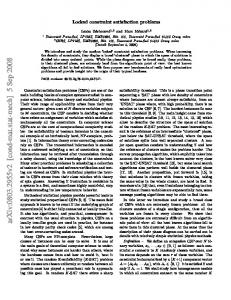
Fig. 1 An arc „a… can be equally represented by two line segments and an angle constraint „b…
constrained system in an automatic manner. In Sec. 5, the technique used to reconstruct a geometric system is explained. To evaluate the validity of the proposed method, experiments are conducted in Sec. 6 using a standard library from mechanical engineering. Finally, conclusions and proposed future work are described in Sec. 7.
2
Representation of Geometric Constraint Systems
2.1 Geometric Constraint Graph. A GCG is an intuitive way to represent the constraints between geometric primitives: the nodes represent the geometric primitives or superprimitives, and the edges represent the constraints between these primitives. Here, superprimitive is defined as a node that is well constrained and contains at least two geometric primitives. A superprimitive acts like a rigid body. For simplicity, when a primitive is mentioned in this paper, it also refers to superprimitive. Formally, GCG can be represented as GCG = 共E,C兲
共1兲
where E represents a set of primitives or superprimitives, and C represents the existing constraints between the elements of E. Usually, geometric constraints can be classified as one of two types: either explicit constraints, which refer to constraints that a user specifies explicitly, such as dimension, or implicit constraints, which are those that are implied in the sketches, such as parallelism and perpendicularity. It is natural for users to express geometric constraints implicitly when they are sketching their design idea on a piece of paper. Although the implicit constraint can provide flexibility for users, it creates inconsistency in a geometric constraint system. One goal of this paper is to take advantage of the implicit constraints embedded in users’ designs to provide an
Fig. 2 GCG representation: „b… is the GCG of „a…
automatic procedure for geometric constraint satisfaction, thus improving the naturalness and efficiency of the design process. In a geometric system, geometric primitives are geometric elements that cannot be further decomposed. In two-dimensional space, the geometric primitives include points, lines, and circles. Generally, a line segment can be represented by two end points and a line passing through the two points. An arc can be similarly represented as two line segments and an angle constraint. For example, the arc shown in Fig. 1共a兲 can be represented by two line segments 共i.e., op1 and op2兲 and an angle constraint 共i.e., s兲. The primitives can also consist of high order curves such as a parabola or an ellipse; however, for the sake of simplicity, this paper focuses on the basic primitives. In Table 1, some popular constraints between any two primitives are listed, and users can extend this constraint list according to their needs. In three-dimensional space, in addition to the zerodimensional points and one-dimensional elements such as lines and circles already mentioned in reference to two-dimensional space, the geometric primitives include some two-dimensional elements such as planes, cylinders, and spheres. Here, a simple two-dimensional example is used to demonstrate the process of constructing a GCG given a geometric system. Figure 2共a兲 shows a triangle with one angle constraint d3 and two distance constraints d1 and d2. According to the definition of a GCG, the constraints of the triangle represented in Fig. 2共a兲 can be represented as a graph in Fig. 2共b兲.
Table 1 A list of geometric constraints between primitives
Journal of Computing and Information Science in Engineering
DECEMBER 2007, Vol. 7 / 323
Downloaded 22 Feb 2008 to 128.46.225.69. Redistribution subject to ASME license or copyright; see http://www.asme.org/terms/Terms_Use.cfm
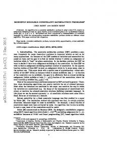
Fig. 3 Four types of CPs between geometric primitives: the node represents a geometric entity and its value is the DOF of the entity; the edge represents the constraint between two entities and its value is the DOF of the constraint
2.2 Geometric Degrees of Freedom and Constraint. To determine the position of a primitive, the primitive must be fixed with respect to a known primitive, i.e., DOF of this primitive is zero with respect to the known primitive. DOF is defined as the number of independent variables that completely specify the displaced or deformed position of an object. For example, a point has two DOFs because it can be described by its coordinate 共x , y兲, a line has two DOFs because it can be described by an intercept distance and an angle with the x axis, and a circle has three DOFs because it can be described by its center 共x , y兲 and a radius r. A superprimitive has three DOFs since it acts like a rigid body. In contrast, the DOC is defined as the reduction in DOFs when a constraint is imposed. In two-dimensional space, a DOC between any two primitives can be 1, 2, or 3. In a GCG, each node can be assigned with a weight equal to its DOF, and each edge assigned with a weight equal to its DOC. In geometric constraint systems, by enumerating all of the types of constraints between points, lines, circles, and superprimitives, the constraint patterns in a GCG can be categorized into four types 共Fig. 3兲, and these four patterns are comprehensive, including all constraint cases. Recall that an arc can be decomposed into two lines with an angle; there are three basic geometric primitives in two-dimensional space: point, line, and circle and the DOFs of points, lines, and circles are 2, 2, and 3, respectively. In particular, the superprimitive is, in fact, a rigid body, and its DOF is 3. By enumerating all possible constraints between points, lines, circles, and superprimitives, it can be found that their respective DOCs can only be 1, 2, or 3 and there are only four patterns for all possible combinations. In Fig. 3, the number beside a node represents the DOF, and the number beside an edge represents the DOC. The constraint patterns can be utilized in a similar way when other geometric primitives such as ellipse or parabola are considered, or the geometric system is in three-dimensional space. The basic principle is to summarize the constraints between any two geometric primitives in a limited set of patterns, which will provide the conditions for graph reduction just like a template matching process. Using these patterns, the position of a node can be determined with respect to the position of another node. In other words, if there is one constraint pattern 共CP兲 as shown in Fig. 3, we can determine the relative position between the primitives or superprimitives that the nodes represent. The four CPs constitute the basis of the graph-reduction operation. Consider, for example, two lines with a constraint of L-L-CL 共see Table 1兲. By checking the CPs in Fig. 3, it is easy to see that they satisfy the pattern CP-2-2a. Therefore, given any one of the two lines, the position of another line can be determined. 2.3 Degree of Coupleness. In this paper, a concept called “DC” is used to describe the constraint relationship between geometric primitives. Given a primitive or superprimitive, if its position is limited by n other primitives, then its DC is n. The DC of a geometric constraint system is determined by the primitive possessing the maximum DC in this system. In practice, given a geometric constraint system, the DC usually is less than 2; if the DC is 3, it is usually impossible to solve the system in an analytic way. For a geometric system with a DC greater than 3, a set of nonlinear equations is required in order to find the solution. Usually, iterative techniques such as the Newton–Raphson method 关2兴 324 / Vol. 7, DECEMBER 2007
Fig. 4 A geometric constraint system whose DC is 3: The relative position of the triangle S1S2S3 with respect to triangle P1P2P3 is determined by the positions of three primitives, i.e., points P1, P2, and P3
are employed to solve the constraint system. For example, the DC of the geometric constraint system in Fig. 4 is 3. The DCs of the two triangles “P1 P2 P3” and “S1S2S3” are 1 because the position of a vertex is limited by a distance constraint with respect to another vertex. However, the relative position between the two triangles is constrained by three primitives. Fortunately, in practice, the DCs of most geometric constraint systems are less than 3 because it is difficult for a designer to confirm the validity of a design scheme with a DC larger than 3. Even for a geometric system whose DC is 2, a designer often needs to use some auxiliary lines to find the final solution. In Sec. 3, we will introduce a graph-reduction strategy that can satisfy a geometric constraint system whose DC is 2 in an analytic manner.
3
Graph Reduction by Matching Constraint Patterns
With the aid of the CPs discussed in Sec. 2, a graph-reduction approach is proposed to solve geometric constraint systems by finding the CP and reducing the edges of a GCG. The reduction process is described step by step with the aid of the example in Fig. 5. The GCG of the geometric constraint system in Fig. 5共a兲 is shown in Fig. 5共b兲. Since each node represents a line or a point, and each edge represents a distance constraint or an angle constraint, the DOF of each node is 2 and the DOC of each edge is 1. Step 共1兲: Select an arbitrary node as the starting point 共or basis node兲 of the graph-reduction process. In this example, we select node p1 as the basis node. • Step 共2兲: Search from the GCG and find a node that meets the following two conditions. 共a兲 Ensure that the node is connected to p1 by an edge, i.e., there is a constraint between this node and p1. 共b兲 Ensure that the CP formed by this node and p1 satisfies any of the CPs listed in Fig. 3. According to this criterion, we find four qualified nodes, i.e., p2, p6, l1, and l6, all of which follow a CP-2-2b pattern. • Step 共3兲: From the qualified nodes, select an arbitrary node and represent the CP between this node and p1 as a new node. For example, we can select node l6 and reduce the CP between l6 and p1 to a new node s1, as shown in Fig. 5共c兲. As described in Sec. 2, this new node represents a superprimitive since it is composed of two primitives, and its DOF is therefore 3. At the same time, the DOC between node p6 and the new node s1 is increased to 2 because the constraints between nodes p6 and l6, and nodes p6 and p1 are inherited by node s1. • Step 共4兲: Define node s1 as the basis node and repeat Step 共3兲. We find only one qualified node, i.e., p6, and it can be •
Transactions of the ASME
Downloaded 22 Feb 2008 to 128.46.225.69. Redistribution subject to ASME license or copyright; see http://www.asme.org/terms/Terms_Use.cfm
Fig. 5 A graph-reduction process †„a…–„q…‡ using the interface-open and reconstruction strategy. The detailed explanation is presented in Sec. 3.
determined that the CP is CP-3-2. This constraint pattern is reduced into a new node, s2, and the resulting GCG is shown in Fig. 5共d兲. • Step 共5兲: Repeat Steps 共2兲–共5兲 until the graph-reduction process cannot be continued anymore. Figures 5共e兲 and 5共f兲 demonstrate this repeating process, and Fig. 5共f兲 represents the GCG that cannot be reduced further. In this example, s4 is determined to be the node that cannot be reduced. We propose an interface-open and reconstruction strategy that is the key to our graph-reduction method. The interface-open and constraint-reconstruction strategy involves reconstructing the GCG by opening reduced nodes that connect to unreduced nodes. In this example, only the reduced nodes p1 and p5 are connected to the unreduced outside nodes. Therefore, the GCG can be reconstructed by opening the two nodes as shown in Fig. 5共g兲. Because the DOFs of nodes p1 and p5 are both 2, we can reconstruct a CP CP-2-2b between them in order to maintain the fact that these two nodes can be reduced. The reconstructed constraints are called virtual
•
constraints, and their usage will be described in detail in Sec. 5. Step 共6兲: Select an arbitrary node from the unreduced nodes as the basis node and repeat Steps 共2兲–共6兲. Figures 5共h兲–5共q兲 demonstrate this repeating process.
From the above explanation, it is not difficult to see that the four CPs are the basis of this graph-reduction algorithm. Unlike the graph-reduction methods proposed by Fudos and Hoffmann 关18兴 and Gao and Zhang 关17兴, in which the CPs are related to multiple primitives, the four patterns in this paper are only related to two primitives. Such a difference will lead to a more efficient matching process. Also, this CP principle can be expanded for higher order primitives such as a parabola or an ellipse. The reduction process can be depicted using a binary tree structure called a reduction tree. Figure 6 shows the reduction trees formed by the reduction process described in Fig. 5. Each tree represents a set of primitives whose positions can be determined with respect to the basis node. Due to the introduction of the
Journal of Computing and Information Science in Engineering
DECEMBER 2007, Vol. 7 / 325
Downloaded 22 Feb 2008 to 128.46.225.69. Redistribution subject to ASME license or copyright; see http://www.asme.org/terms/Terms_Use.cfm
Fig. 6 The reduction trees of the example in Fig. 5: „a… is the reduction tree comprised of primitives p1, l6, p6, l5, and p5, „b… is the reduction tree comprised of primitives p4, l4, p5, l3, and p3, and „c… is the reduction tree comprised of primitives p2, l2, p3, l1, p1, and p5
interface-open strategy, there are common nodes between these reduction trees. With the aid of these common nodes, these reduction trees can be correlated, i.e., the position of a reduction tree with respect to that of another tree will be determined. If we use this reduction process step by step with the help of the practical example in Fig. 6, it can be seen that this process is similar to the reasoning process of a human being.
4
Ill-Constrained Geometric Systems
As with previously described methods, the reduction algorithm described in Sec. 3 assumes a well-constrained geometric system. However, a well-constrained geometric system seldom occurs in the initial conceptual design stage because it is a very tedious process, and it may even be impossible for designers to check their constraint consistence while they are sketching their ideas. Instead of specifying each constraint explicitly, most of the constraints are implied in the sketches, similar to the perpendicular constraints shown in Fig. 7共a兲. The ability to handle an illconstrained geometric system in an automatic manner can free designers from tedious work checking the redundancy of constraints, and will allow them to put their efforts into the creative work, thus improving the naturalness and efficiency of a design process. Ill-constrained geometric systems can be either over- or underconstrained. Figure 7共a兲 is an example of an underconstrained system, while Fig. 7共b兲 is an example of an overconstrained system. In the overconstrained system, contradictions will usually exist between the constraints, thus causing confusion for the geometric constraint solver since it does not know which constraints should be chosen for reasoning purposes. For example, if the
Fig. 7 Example of ill-constrained systems: „a… This triangle is underconstrained because there are not enough constraints for a unique solution. „b… Here, it is overconstrained because there are too many constraints for a unique triangle.
326 / Vol. 7, DECEMBER 2007
angle constraint s1 is chosen while s2 is discarded, the final angle between b and c after constraint satisfaction might be different from s2. Usually, whether or not a system is ill constrained may be determined by establishing whether or not the reduced components can be assembled together. If there are several possible ways to combine them together, then this system is overconstrained. As the example in Fig. 7共b兲 shows, choosing either angle constraint s1 or s2 will lead to a possible solution for the triangle. As the example in Fig. 7共a兲 shows, if there is no way to assemble them together, then this system is underconstrained. These criteria can be used to inform users of the current constraint status, thus prompting users to perform any necessary corrections. However, having to check for ill-constraint results in obvious inefficiency and unnaturalness for a large geometric system where the geometric system is seriously over- or underconstrained. This is due to the fact that the constraint solver has to prompt users to correct constraints frequently, even if the constraints are obviously implied in the sketches, such as that of the perpendicular constraint in Fig. 7共a兲. To overcome this problem and take advantage of the implied constraints, a priority-based strategy is introduced to handle an ill-constrained geometric system automatically. The basic theory is based on two assumptions: 共1兲 That enough constraints to assure a possible solution are implied in a designer’s sketches and 共2兲 that the geometric constraints have some kind of priority with respect to each other. The first assumption implies that a geometric system is always overconstrained, and the second assumption actually assigns a priority value to each constraint. One simple way to determine the implied constraints is to define their existing relative position as the constraints of two primitives. For example, the lengths of the edges and the angles between them can be defined as the implied constraints in the sketch shown in Fig. 8共a兲. In our prototype system, six levels of priorities are defined and each level is given a value from 0–5: “0” has the highest priority, and “5” has the lowest priority. Generally, explicit constraints have a higher priority for graph reduction than implicit constraints do. To work with an overconstrained system where there are redundant explicit constraints, this priority strategy is applied not only to implicit constraints but also to explicit constraints due to their geometric properties. In Table 2, some common constraints and their priorities are listed. The explicit constraint P-L-E has a higher priority than the distance constraint because the former cannot be changed while the latter can. The priority level can be expanded and the assignment strategy can also be modified according to specific needs. For example, if the 45 deg chamfer constraint is frequently used in the design, then it can be added to the implied constraint list and assigned with a higher priority than an arbitrary angle constraint. With the aid of the priority strategy and the GCG representation, we can construct a PGCG for a given geometric constraint system, where the node is assigned with a weight indicating the DOF of the geometric primitive and the edge; and the edge is assigned with a dual weights indicating the DOC and the priority of the geometric constraint. For example, the PGCGs of the two examples in Fig. 7 are shown in Fig. 8, where the dash lines represent the implicit constraints, the solid lines represent the explicit constraints, and the constraint types and their priorities are indicated in a format “X-X-X 共#兲: constraint type 共priority兲.” It can be seen from the two examples that they have the same GCG, but have different priorities for some of the constraints. Given a PGCG, the reduction process is similar to the steps mentioned in Sec. 3. The only difference lies in the fact that if multiple CPs are found, only the one with the highest priority is reduced; however, when multiple CPs are found with the same priority, any one of them can be reduced. Thus, choosing different CPs might lead to different results. Unlike the traditional manner 关16兴 in which a designer is asked to correct constraint whenever an overconstraint or underconstraint occurs, this approach will let Transactions of the ASME
Downloaded 22 Feb 2008 to 128.46.225.69. Redistribution subject to ASME license or copyright; see http://www.asme.org/terms/Terms_Use.cfm
Fig. 9 Geometric entity reconstruction process †„a…–„h…‡. Detailed explanation is presented in Sec. 5.
Fig. 8 „a… is the PGCG of the example in Fig. 7„a… and 7„b…, is the PGCG of the example in Fig. 7„b…
the designer to check the final result and only then perform any further correction. Although Joan-Arinyo et al. 关19兴 tried to transform an ill-constrained system into a well-constrained one, their method could only be used for an underconstrained problem. In contrast, some numerical based methods such as in Ref. 关2兴 can only deal with an overconstrained system. In their genetic simuTable 2 Priority levels for geometric constraints
lated annealing algorithm, Liu et al. 关20兴 used the number of the equations to be solved to check the over- and underconstrained problems, but it is still difficult to figure out how to delete/add constraints to maximally reflect a designer’s original intention. In contrast, our method can be used to deal with the over- and underconstrained problems intuitively and automatically.
5 Geometric Constraint System Reconstruction by Virtual Constraint As described in Sec. 3, a reduction tree provides a record of the process of constraint satisfaction. Therefore, a regular twodimensional shape can be reconstructed by traversing its reduction tree from “leaf” to “root.” Below, the same example given in Fig. 5 is used to describe the reconstruction process: Step 共1兲: In the reduction tree shown in Fig. 6共a兲, p1 and l6 are the starting points of a graph reduction. The constraint type between p1 and l6 is P-L-E 共see Table 1共2兲兲. We can then generate a line and a point that satisfy this kind of constraint, as shown in Fig. 9共a兲. The line and point can be placed at any position since they are the reference basis, i.e., the first geometric element that we are going to redraw. • Step 共2兲: When we traverse this tree continually from bottom to top, node p6 is found. There are two constraints between p6 and s1: the first is P-P-D 共Table 1共1兲兲 between p6 and p1, the second is P-L-S 共Table 1共3兲兲 between p6 and l6. Given the positions of p1 and l6, it is easy to determine the position of point p6 under the two constraints. The result is shown in Fig. 9共b兲.
•
Journal of Computing and Information Science in Engineering
DECEMBER 2007, Vol. 7 / 327
Downloaded 22 Feb 2008 to 128.46.225.69. Redistribution subject to ASME license or copyright; see http://www.asme.org/terms/Terms_Use.cfm
•
Step 共3兲: Similar to Step 共2兲, the positions of other nodes can be determined, and the results are shown in Figs. 9共c兲 and 9共d兲. It is worth pointing out that there are multiple solutions that can be found using this reconstruction process. An example of this is shown in Fig. 9共e兲, where there are two possible solutions for point p5. To avoid this problem, the relative positions between primitives in the original drawing are used to ensure that the correct solution has the same relative positions between primitives as the original drawing. The strategy that we adopt is to determine on which side a geometric primitive lies with respect to other geometric primitives. In this example, since p5 lies on the left side of line p6 p1, the correct position of point p5 is the one shown in Fig. 9共d兲.
By using the proposed reconstruction process, the position of the reduction tree 6共b兲 can be determined, and the result is shown in Fig. 9共f兲. When calculating the position of node p5, for the reduction tree shown in Fig. 6共c兲, it can be seen that there are two constraints between p5 and s12: one constraint between p5 and p1 and the other constraint between p5 and p3. However, the constraint types between p5 and p1, and p5 and p3 are not known. In order to solve this problem, a concept called virtual constraint is proposed, which is a component of the interface-open and reconstruction strategy. When a reduction tree is generated, we can build the virtual constraints by connecting every two nodes and computing the distance between them. Virtual constraints can be simply regarded as being equivalent to the distance constraint, as the distance between any two nodes within a reduction tree is determined with respect to each other. In the example given in Fig. 9共d兲, the distances between p5 and p1 can be computed because their relative positions are determined. Similarly, the distance constraint between p5 and p3 can be computed, as shown in Fig. 9共f兲. In this way, the reduction tree in Fig. 6共c兲 is reconstructed and the result is shown in Fig. 9共g兲. The dash lines representing the constraints between the nodes are virtual constraints. With the aid of these virtual constraints, the reconstructed results can be assembled, such as those of Figs. 9共d兲, 9共f兲, and 9共g兲, into a whole body, as shown in Fig. 9共h兲.
6
Implementation and Experiment
The algorithm introduced in this paper was implemented on the platform of AutoCAD and written in C⫹⫹. The reason that AutoCAD was chosen is that it has a clear graphical user interface and strong data representation. The prototype consists of three basic components: PGCG construction, graph reduction, and geometric system reconstruction. In the first components, a linked chain data structure is used to represent the PGCG of a geometric constraint system in order to efficiently search for the predefined CPs. Once the sketches are transformed into PGCG, the reduction module will be executed and the reduced sequence is represented in a tree structure. Finally, a new geometric system is reconstructed by traversing the reduced tree and computing the new position of the primitives. To test the validity of our constraint solver, we used a standard library from mechanical fields, which contains 221 legacy drawings. The DCs of the drawings in this library are less than 3. The experiments indicate that all of the legacy drawings in this standard library can be driven correctly and that the driving process can be finished in less than 1 s. With the help of the priority strategy, the driving process is done automatically by checking the priorities and only reducing the node with the highest priority. Users are freed from any manual intervention in the constraint satisfaction process. In Fig. 10, some examples are used to demonstrate the validity of our proposed geometric constraint solver. The top line shows the original geometric drawing with certain constraints, while the bottom line shows the results after some constraints are modified and updated by our solver. These three examples contain both the explicit and implicit constraints. For 328 / Vol. 7, DECEMBER 2007
Fig. 10 An example using our geometric constraint solver. Changing the parameters will automatically lead to the results that satisfy the specified constraints and the implied constraints.
example, in Fig. 10, many constraints are implied, including tangent, parallel, and perpendicular. When the dimension of one entity is changed, the other related geometric entities are all changed, respectively. Meanwhile, their constraint relationships are not changed. In the past, the constraint solver has usually been used for designs in which the “sketches” are already beautified. However, a designer would likely prefer to use “freehand sketches” to express his ideas. The essential relationship between freehand sketches and the design process has been highlighted by many researchers 关21–24兴, and the constraint status for freehand-based sketches is generally very inconsistent. Under these circumstances, our method based on PGCG will have obvious advantages. We have applied the constraint solver introduced in this paper successfully to the geometric constraint satisfaction of freehand sketches, where the algorithms regarding freehand sketch parsing, primitive recognition, and implicit constraint detection are explained in detail.
7
Conclusion
In this paper, a new geometric constraint solver is introduced. Unlike previous approaches, our method aims to provide an automatic solution to an ill-constrained geometric system by making Transactions of the ASME
Downloaded 22 Feb 2008 to 128.46.225.69. Redistribution subject to ASME license or copyright; see http://www.asme.org/terms/Terms_Use.cfm
use of the implied constraint in sketches, thus requiring minimal intervention by users. The key contribution lies in the fact that there is a limited set of CPs that only reflect the constraints between two primitives, and the introduction of the PGCG and the graph-reduction algorithm.
Acknowledgment This material is partly based on the work supported by the National Science Foundation under Grant IIS No. 0535156.
References 关1兴 Durand, C., 1998, “Symbolic and Numerical Techniques for Constraint Solving,” Ph.D. thesis, Purdue University, West Lafayette, IN. 关2兴 Stoer, J., and Bulirsch, R., 1993, Introduction to Numerical Analysis, 2nd ed., Springer-Verlag, New York. 关3兴 Allgower, E. L., and Georg, K., 1990, “Continuation and Path Following,” Acta Numerica, 2, pp. 1–64. 关4兴 Lamure, H., and Michelucci, D., 1996, “Solving Geometric Constraints by Homotopy,” IEEE Trans. Vis. Comput. Graph., 2共1兲, pp. 28–34. 关5兴 Rojas, J. M., 1999, “Solving Degenerate Sparse Polynomial Systems Faster,” J. Symb. Comput., 28共1–2兲, pp. 155–186. 关6兴 Kondo, K., 1992, “Algebraic Method for Manipulation of Dimensional Relationships in Geometric Models,” Comput.-Aided Des., 24共3兲, pp. 141–147. 关7兴 Wang, D., 1998, “Decomposing Polynomial Systems Into Simple Systems,” J. Symb. Comput., 25, pp. 295–314. 关8兴 Brüderlin, B. D., 1987, “Rule-Based Geometric Modeling,” Ph.D. thesis, Swiss Federal Institute of Technology, Zürich, Switzerland. 关9兴 Aldefeld, B., 1988, “Variation of Geometries Based on a Geometric Reasoning Method,” Comput.-Aided Des., 20共3兲, pp. 117–126. 关10兴 Verroust, A., Schonek, F., and Roller, D., 1992, “Rule-Oriented Method for Parameterized Computer-Aided Design,” Comput.-Aided Des., 24共10兲, pp. 531–540. 关11兴 Kramer, G. A., Solving Geometric Constraints Systems, MIT Press, Cambridge.
关12兴 Hoffmann, C. M., Lomonosov, A., and Sitharam, M., 1997, “Finding Solvable Subsets of Constraint Graphs,” Lect. Notes Comput. Sci., 1330, pp. 163–197. 关13兴 Lee, J. Y., and Kim, K., 1998, “Geometric Reasoning for Knowledge-Based Design Using Graph Representation,” Comput.-Aided Des., 28共10兲, pp. 831– 841. 关14兴 Li, Y. T., Hu, S. M., and Sun, J., 2000, “Hybrid Model of Geometric Constraint Satisfaction,” Journal of Computer Research and Development, 37共10兲, pp. 1233–1239. 关15兴 Ait-Aoudia, S., Jegou, R., and Michelucci, D., 1993, “Reduction of Constraint Systems,” Proceedings of the International Conference on Computer Graphics, Bombay, India, pp. 83–92. 关16兴 Bouma, W., Fudos, I., Hoffmann, C. M., Cai, J., and Paige, R., 1995, “A Geometric Constraint Solver,” Comput.-Aided Des., 27共6兲, pp. 487–501. 关17兴 Gao, X. S., and Zhang, G. F., 2003, “Classification and Solving of Merge Patterns in Geometric Constraint Solving,” Proceedings of the Shape Modeling International, Seoul, Korea, pp. 89–98. 关18兴 Fudos, I., and Hoffmann, C. M., 1997, “A Graph-Constructive Approach to Solving Systems of Geometric Constraints,” ACM Trans. Graphics, 16, pp. 179–216. 关19兴 Joan-Arinyo, R., Soto-Riera, A., Vila-Marta, S., and Vilaplana-Pastó, J., 2003, “Transforming an Under-Constrained Geometric Constraint Problem Into a Well-Constrained One,” Proceedings of the ACM Symposium on Solid Modeling and Applications, Seattle, WA, pp. 33–44. 关20兴 Liu, S. L., Tang, M., Chou, S. C., and Dong, J. X., 2004, “Solving Geometric Constraints With Niche Genetic Simulated Annealing Algorithm,” Proceedings of the International Conference on Computer Supported Cooperative Work in Design, Xiamen, China, pp. 679–684. 关21兴 Van Dijk, C. G. C., 1995, “New Insights in Computer-Aided Conceptual Design,” Des. Stud., 16共1兲, pp. 62–80. 关22兴 Kavakli, M., and Gero, J. S., 1999, “Sketching as Mental Imagery Processing,” Des. Stud., 22共4兲, pp. 347–364. 关23兴 Tversky, B., 1999, “What Does Drawing Reveal About Thinking,” Proceedings of the Visual and Spatial Reasoning in Design; Key Centre of Design Computing and Cognition, Sydney, Australia, pp. 93–101. 关24兴 Beryl, P., and Mark, A., 2002. “Computer-Aided Sketching to Capture Preliminary Design,” Proceedings of the ACM International Conference Proceeding Series on Third Australasian Conference on User Interfaces, Melbourne, Australia, Vol. 7, pp. 9–12.
Journal of Computing and Information Science in Engineering
DECEMBER 2007, Vol. 7 / 329
Downloaded 22 Feb 2008 to 128.46.225.69. Redistribution subject to ASME license or copyright; see http://www.asme.org/terms/Terms_Use.cfm