This full text paper was peer reviewed at the direction of IEEE Communications Society subject matter experts for publication in the IEEE INFOCOM 2007 proceedings.
Proactive Scan: Fast Handoff with Smart Triggers for 802.11 Wireless LAN Haitao Wu, Kun Tan, Yongguang Zhang
Qian Zhang
Wireless & Networking Group Microsoft Research Asia {hwu, kuntan, ygz}@microsoft.com
Department of Computer Science Hong Kong University of Science and Technology
[email protected] AP infrastructure, or to require each mobile device to upgrade with new hardware. Granted, fast handoff in 802.11 is not a new problem; many researchers have studied this problem and proposed various schemes. However, none of the prior work meets all the requirements we listed above. As we will explain in detail in the next section, the previous proposals either require changing APs or adding new hardware. Furthermore, none of the previous work has addressed the link asymmetry phenomenon that many have observed in real experiments, which can negatively affect the handoff performance. We have developed a new 802.11 handoff scheme called Proactive Scan. It is a software module residing at an 802.11 NIC (network interface card) driver to make intelligent handoff decision. The basic idea is to decouple the time consuming channel scanning from the actual handoff, and to execute the scanning early and in a way non-intrusive to the ongoing traffic. The scheme further uses an intelligent handoff trigger for link asymmetry and for better trigger accuracy. We have implemented this and through experimental study proven that it has achieved our goal and met all the listed requirements. We claim the following contributions with this research. First, our work shows that it is essential to decouple the timeconsuming channel scanning from actual handoff, and through adaptive algorithms it is feasible to do scan accurately without human-detectable interruptions to ongoing traffic. Second, we are among the first to address the link asymmetry problem in handoff, and come up with a sophisticated trigger that covers both uplink and downlink quality. And lastly, through our implementation and experimental study, we show that it is possible to achieve fast handoff for VoIP applications in the current 802.11 network, without special AP support. The rest of this paper is organized as follows. Section II describes the problems we are addressing and related work. Section III gives the basic idea of our Proactive Scan approach. Section IV and Section V explain adaptive rate trigger and the proactive scan details. Then Section VI presents the system design and implementation issues and Section VII describes the experimental study. Finally, Section VIII concludes the paper.
Abstract— It has been a challenging problem to support VoIPtype delay sensitive applications in an 802.11 wireless LAN, because the standard handoff procedure implemented in many current 802.11 products occurs a delay deem unacceptable to VoIP users. To reduce this delay, we have developed a fast handoff scheme called Proactive Scan. It employs two new techniques. The first is to decouple the time-consuming channel scan from the actual handoff, and to eliminate channel scan delay by doing scan early and interleaving it with ongoing traffic in a non-intrusive way. The second technique is a smart trigger that takes into account both uplink and downlink quality and explicitly addresses the link asymmetry which has yet not been touched in previous work. Through implementation and experimentation study, we have shown that Proactive Scan does provide fast handoff and satisfactory performance to VoIP applications. Further, it is a software-only client-only solution that any mobile device can use in any existing 802.11 networks. Keywords-Proactive Scan, Handoff, Asymmetry, VoIP, WLAN
I. INTRODUCTION Large scale 802.11 wireless networks with multiple APs (access points) have been widely deployed in university campuses, office buildings, airport terminals, and other public venues. Many places around the world have developed plans to roll out city-wide 802.11 coverage, such as San Francisco, Philadelphia, Paris, and Taipei, etc. One of the goals for these networks is to support seamless roaming when a user moves from the coverage area of one AP to another. For example, a user making Voice over IP (VoIP) calls with his/her PDA or WiFi-equipped phone should not experience service disruptions or quality degradations to the phone conversation while he/she is moving around in the network or handing off from one AP to another. Unfortunately, it is challenging to support such seamless roaming in today’s 802.11 networks. This is because the standard 802.11 handoff procedure incurs a significant delay, typically in the magnitude of hundreds of milliseconds to several seconds, depending on the configurations and operation mode. During this handoff period, the data service must be disrupted. A silent gap of this magnitude is simply unacceptable to VoIP-type delay-sensitive applications, as it is widely agreed that for a human to not notice any disruption in voice conversation, the gap should be smaller than 50ms. The goal of this research is to solve the above problem and support roaming VoIP-type applications in any 802.11 network. The objective is to develop a fast handoff scheme with a handoff delay less than 50ms. We further require a client-only software-only solution in this paper, because it is otherwise expensive to modify or upgrade the already deployed
II.
PROBLEM DEFINITIONS AND RELATED WORK
In this section, we give background and related work for two problems we are addressing: the long channel scanning delay and the lack of adequate handoff triggers for link asymmetry. A. Brief description of 802.11 handoff procedure In an 802.11 network, an area is covered by multiple APs, each operating in one of the many channels. A single-radio
0743-166X/07/$25.00 ©2007 IEEE 749
This full text paper was peer reviewed at the direction of IEEE Communications Society subject matter experts for publication in the IEEE INFOCOM 2007 proceedings.
channel. The common practice in current 802.11 products is to set beacon intervals at 100ms and passive scan wait time a bit longer at 105ms. In active scan method, the station actively broadcasts a probing request frame (message A) before waiting for APs’ probe responses (message B). The wait time is either MinChannelTime (if the station receives no response by the time) or MaxChannelTime (otherwise). These two parameters are defined in the 802.11 standard. In the second phase of handoff, the reconnection delay consists of link authentication delay (message E and F) and reassociation delay (message G and H). The re-association delay includes the time for IAPP (Inter-Access Point Protocol) [3] delay for context switching between old AP and new AP. In the current 802.11 implementations, the entire handoff delay ranges from hundreds of milliseconds to several seconds. Majority of this delay is the channel scanning delay because the reconnection phase only takes tens of milliseconds. This long delay obviously makes VoIP-type applications undesirable. Our goal is to achieve one to two magnitude of reduction in handoff delay. Our focus will be on reducing the channel scanning delay.
client station can only operate in one channel at a time, and it can only associate and maintain connectivity with one AP. However when it detects a link quality deterioration with its current AP, it will attempt to find a new AP with better link quality in current or other channels, and switch to the best available. Figure 1 below illustrates this procedure.
Figure 1. The handoff procedure by the IEEE 802.11
Once the handoff procedure starts, the ongoing data traffic will be interrupted until the handoff procedure finishes. This service interruption time mainly consists of two phases: the channel scanning delay, during which the station scans all (neighbor) channels to collect the information about neighboring APs, and the reconnecting delay, during which the station reconnects to the newly selected AP. In Figure.1, we mark t0 as the time when the service has been interrupted, t1 as the time that the channel scanning has completed, and t2 as the time that the station has re-associated with the new AP and ready for resuming data communication. Note that channel scanning starts actually at time ta because it can take (ta- t0) time for the station to detect service interruption event and trigger handoff. The handoff trigger usually is very conservatively to avoid unnecessary scanning cost if the current AP is still the best among neighbors (mis-triggered handoff). In the first phase of handoff, the station scans all channels to collect neighboring APs information. Thus, the channel scanning delay is determined by three factors: the number of candidate channels, the scan time at each channel, and a fixed channel switching overhead δ (but NIC-dependent, usually a few milliseconds in the current products). The number of channels depends on the type of NIC. For example, 11b has 11 channels, 11a has 13 orthogonal channels. For our Atheros 5212 NIC a/g/b combo NIC, it has 28 channels to scan: 11 for 11b, 13 for 11a, and 4 for turbo mode. The time to scan a channel depends on the scanning method. In passive scan method, the station passively waits to hear periodic beacons transmitted by the neighbor APs in the new
750
B. Related work on improving handoff delay Most of the related work also focuses on reducing the channel scanning delay. The first class of work proposes methods to reduce the number of channels to scan during handoff. In neighbor graph approach [9-11], stations leverage on pre-obtained neighboring APs information and scan only the non-empty (with AP nearby) channels. 802.11k [5] has defined the frame format for reporting such neighboring information. Cisco CCX [13] has taken a similar approach, where stations communicate with APs to obtain neighboring APs information. However, recent work [8] shows that the APs are usually deployed with high density, which means the probability of an empty channel (with no AP nearby) is low. Another class of methods is to reduce the time spent on scanning each channel. For example, Syncscan [12] greatly reduces the passive scan time by having all APs synchronize their beacon broadcast time and having stations jump to a channel right before that time. This however requires a precise synchronization of all parties so that APs have to be modified. Some researchers have also attempted to completely eliminate handoff delay. For example, if a client has multiple radios, it can use one radio for data communication and another for scanning and handoff [17]. Others have also proposed a sensor overlay [18] to collect neighboring AP information and assist a station’s handoff procedure. None of the above prior work meets our goal because they require none trivial modifications to current APs or require additional hardware. In contrast, our Proactive Scan approach practically eliminates the channel scanning delay without changing APs or adding new hardware. Our approach is much easier to deploy. Further more, our approach addresses the link asymmetric problem and improves handoff triggering, which as far as we know has not been considered by the related work. We believe an accurate handoff trigger is essential in the performance of any handoff scheme. Triggers widely used in 802.11 include the RSSI (Received Signal Strength Indicator) [8], the number of retransmission at the station, the loss of beacons [8], etc.
This full text paper was peer reviewed at the direction of IEEE Communications Society subject matter experts for publication in the IEEE INFOCOM 2007 proceedings.
Most of the prior work uses only one simple trigger and we are among the first to consider sophisticated triggering that covers both uplink and downlink. Reducing reconnection delay is a relevant work orthogonal to our approach. Recent study has shown that this delay can be reduced by improving security algorithms [4,7]. Further, 802.11r [4] defines the frame format and Information Element related for fast BSS (Basic Service Set) transition. In our experiment, we also find that the time cost of the re-connecting phase is less than 10ms if using Open System Authentication [1] and no IAPP, where the IAPP delay is determined by wired IAPP server and link delay. In [19], a wireless NIC is virtualized to multiple interfaces by frequently switching the physical NIC between one ad hoc and one infrastructure network at hundreds of milliseconds. However, it can not directly be applied to handoff scenario since the network information is not known before scan and how to connect to multiple APs are not addressed. C. Link asymmetry in 802.11 networks In 802.11 wireless networks, link asymmetry will likely happen due to the following reasons. First, AP and station likely have different transmission and receiving capabilities. Second, wireless path loss in the two directions can be different. And third, AP and station will have different hardware and software implementations. To understand link asymmetry better, we measure uplink and downlink FLR (frame loss ratio), the loss probability of one link layer frame over the wireless media. We measure both FLRs separately and make a comparison. The instrument packets are UDP broadcast packets, with 32-byte frame size and 50 packet/s. We use broadcast and not uni-cast frames to avoid retransmissions. The low packet rate is to make sure no packet will be dropped due to buffer overflow. We use the testbed in Figure 8 for our measurement. We put one 802.11a OriNOCO AP 4000 at location A and one Dell D410 laptop at location B, C, and D. The distance between location B, C, D and A is 2.2m, 4.5m and 8.6m respectively. Note that in our experiment we find that the FLR is affected by obstacles such as plants, walls, and pillars, thus the results are location dependant, not distance dependant. The AP is at channel 161. The raw link rates for broadcast frame are set to 24Mbps for both uplink and downlink. The NIC in the laptop is a Linksys Atheros 5212 a/g/b combo card. Its transmission power is set to the highest and then the lowest level to demonstrate the effect of a power constrained mobile station. Power Location B(2.2m) C(4.5m) D(8.6m)
Min Tx power Uplink Downlink 2.94% 0% 5.96% 0% 97% 0.3%
Max Tx power Uplink Downlink 1.9% 0% 3.92% 0% 7.7% 0%
Table.1 The FLR of uplink and downlink at different locations
Table.1 compares the uplink and downlink FLRs. It is clear that downlink FLR is consistently lower than uplink FLR, which is only 0~0.3% for all these three locations. The transmission power at station affects the uplink quality greatly, resulting in severe asymmetry. Since 802.11 requires link layer ACK at backward direction, poor performance (high FLR) at any direction affects the data traffic performance.
751
D. Impact of link asymetry on 802.11 handoff The phenomenon of link asymmetry can also severely affect 802.11 handoff. First, most implementations that we are aware of use a single trigger that measures quality at one transmission direction (downlink or uplink) and ignores the other. This can lead to the inability to detect poor performance in the other direction. Second, if a station uses passive scan in the scanning phase, it will only have the downlink quality for handoff decision. But in our experiment, we often observe the scenario that AP’s beacon can be heard by station, while the station’s transmission is not received by AP. A handoff under this condition will lead to timeouts and long delay in the reconnection phase. The cause of these problems lays on the use of inadequate handoff triggers in current 802.11 implementations. The purpose of handoff triggers is for a station to monitor the link quality to current AP and detect performance deteriorations. Triggers that are widely used in 802.11 are based on the RSSI (Received Signal Strength Indicator) [8], the number of retransmission at the station, or the loss of beacons [8], etc. All these triggers measure one metric only and on one transmission direction. The measurement is done at the station. RSSI represents the downlink quality. Ideally BER (Bit Error Rate) or FLR should be used to represent the link quality since it directly gives the results for any transmission made on such link. However, it is difficult to obtain their value in a real system in real time. People may argue that it’s possible to measure the uplink FLR by tracing the number of total (re)transmissions for uni-cast data frames and those ACKed by AP. However, we believe in practice it is not a good enough trigger because of the following reasons. First, commercial NIC typically involves rate adaptation at packet level and the FLRs under different rates are fairly different, so the measured FLR is actually a mixed one for different rates and hard to use for trigger. Second, in VoIP application that employs silence detection and other voice compression techniques, the traffic is bursty and unbalanced between uplink and downlink. Thus, when the user on WLAN is listening while the peer is talking, there are few packets on uplink direction to update FLR and trigger handoff. Since BER or FLR is assumed to be determined by SINR (signal to interference ratio), SINR can also represent link quality but it is equally difficult to obtain its value in real time. Therefore, people assume a stable interference and use the signal strength, RSSI, to represent link quality; it has been shown that there exists a relationship between obtained goodput and RSSI [8]. People have also directly used continuous number of frame retransmissions at the station as a handoff trigger. It represents the uplink quality somehow. However, we believe it is also not a good enough trigger because we have observed temporary burst frame loss for uplink direction even when the link is good to use after retransmission. This can trigger unnecessarily scans, especially when the station is a mobile device with power constraint. In addition, similar to the constraint of measuring uplink FLR, the unbalanced and bursty real time traffic may also cause few uplink traffic to use this trigger. None of these triggers considers both uplink and downlink quality in handoff decision, which is clearly warranted due to the link asymmetry. The challenge of our work is to design sophisticated triggering that covers both uplink and downlink.
This full text paper was peer reviewed at the direction of IEEE Communications Society subject matter experts for publication in the IEEE INFOCOM 2007 proceedings.
Then we feed this model into NS2 to obtain the achieved throughput of a greedy UDP on such a link. It is clearly evident that for a certain SINR, there is an optimal rate that achieves the maximal throughput. Many rate adaptive algorithms are trying to dynamically set its transmission rate to that optimal value based on currently observed link conditions. In current commercial 802.11 interfaces, rate adaptation algorithms are already implemented as default [14]. This provides us a new way to infer the channel condition. Moreover, the adapted transmission rate is actually a metric that represents the quality on both uplink and downlink. It is because the 802.11 protocol explicitly requires an ACK frame for each unicast data packet. Therefore, losses in either data frames or ACKs are counted as a failed transmission at source node, which results in adjusting of rate.
One approach is to modify the AP so that it measures uplink quality like RSSI and feeds it back to each station. This however requires significant change and state-keeping at AP. We therefore pursue a station-only solution. III.
OUR APPROACH
We have developed a fast handoff mechanism called Proactive Scan. It is a software module residing at an 802.11 NIC driver to make handoff decisions. The basic ideas behind Proactive Scan are outlined as follows. First, we use proactive scanning to eliminate the appearance of channel scanning delay. That is, a station will actively probe other channels early and when the handoff trigger is fired it has all the updated information to jump to reconnection phase. We divide the actual channel scanning phase into small pieces and interleave them with normal ongoing data traffic. We design each piece to be small enough (average 10 milliseconds) so that it introduces no humandetectable interruption to ongoing VoIP sessions. The active probing is used in the proactive scanning, both for reducing the scanning time (smaller pieces) on each channel, and ensuring the probed AP works for both uplink and downlink. We further use adaptive algorithm to adjust the scanning interval and channel searching sequence to maintain always updated information for a seamless handoff. This way, we can reduce the service interruption time during handoff to a mere tens-ofmillisecond suitable for VoIP-type applications. Second, we use a -based handoff trigger that leverages the transmission rate adaptation method commonly used in 802.11 NIC. This trigger covers both uplink and downlink quality and addresses the link asymmetry issue. Further, we separate the handoff triggering decision into two, one to trigger proactive scan (called the scan trigger) and the other to trigger actual handoff. This ensures that we can achieve the right balance between scan overhead and handoff timing accuracy. We will describe both ideas in details in the remaining of this paper. We will prove our ideas through analysis, implementation, and experimentations. For the ease of description, we will explain the handoff triggering first, then the mechanism of proactive scan.
UDP Throughput(Mbps)
30
Link Modulation Rate 54Mbps 36Mbps 24Mbps 12Mbps 6Mbps
25 20 15 10 5 0 0
50
100
150
200
Distance(m)
Figure 2. The comparision of throughtput versus distance for 802.11a
To show that the adapted rate in commercial NIC is also reasonable for both handoff and proactive scan trigger, we measure the averaged rate values from one AP to stations at different locations in a typical office floor. The AP is a Proxim OriNOCO AP-4000 and works on channel 161. We select the places marked as ‘x’ in the map of Figure.8, and measure the averaged rate adapted by AP when transmitting to station. The measured results are shown in Figure.3. From the figure we observe that: 1) there exist areas that the AP can reach station by certain rates, and smaller rate covers larger area centered at the AP. Therefore, rate drops to certain value is good indicator for handoff. 2) the speed of rate dropping or rising can be used as the indicator of how fast the user is moving.
IV. TRIGGERS FOR PROACTIVE SCAN In this Section, we first give the rationale for choosing transmission rate as trigger and then illustrate how to use rate to trigger handoff and scan.
AP 4000 50 45
A. Rationale and experiment of rate based trigger Multiple rates have been defined in the 802.11 standard. For example, in 11b, there define four rates to use: 1, 2, 5.5, 11Mbps; while in 11a, there are more rates from 6Mbps to 54Mbps. Higher data rates are achieved by using more efficient modulation schemes, which also requires higher SINR to decode. Therefore, it is not always the best to choose the highest data rate in a low SINR channel, since the achieved performance may be low due to large FLR. In Figure.2, we show a simulated relationship between the achieved throughput and the distance (or SINR) in 802.11a with different data rates. We obtain this figure by using both Matlab and NS2 [20] simulations. Basically, we first use Matlab link simulation on OFDM channel to obtain the relationship of BER over SINR.
Rate(Mpbs)
40
50
35
40
30
30
25
20
20
10
2
0
4 2
6 x
4 y
6 8
15 10 5
8
Figure 3. The adapted rate from AP to stations at different locations
To make a comparison for using transmission rate and RSSI as trigger, we also measured the averaged RSSI value at
752
This full text paper was peer reviewed at the direction of IEEE Communications Society subject matter experts for publication in the IEEE INFOCOM 2007 proceedings.
resumes at 29s again. The proactive scan collects enough information to make handoff decision.
same locations, which are shown in Figure.4. We observe similar trend for RSSI with rate. Moreover, when station is at the edge of the coverage range, the changes of RSSI becomes smaller, so its indication to handoff is not very clear. On the contrary, the transmission rate drops sharply when it’s close to the edge, which means it still can be served as a good indicator even compared with RSSI.
B. Scan trigger and handoff trigger As we’ve mentioned, adapted transmission rate is actually a metric that represents the quality of both uplink and downlink since 802.11 requires ACK on reverse direction. However, using only the transmission rate at station is not good enough, since VoIP traffic may be highly unbalanced and bursty so that there may be the case that few packets are on uplink direction. Thus, we use the adapted transmission rates both at AP and station. The AP’s transmission rate is obtained at station when receiving data frames from AP. The rate metrics are valid only when: 1) there are certain number of frames transmissions made in the time sliding window, 2) the slope of the smoothed rate is negative than a predefined threshold. The first condition is to guarantee that current rate is adapted with enough frames, and the second one is to ensure rate has been changed and becomes lower. The slope is actually calculated by historical values in a time windows as follows. Assume that the size of the window is s, i.e., it keeps s recent values. The historical smoothed rate values after TSWMA are labeled by ri, i=1,..s, and smaller index means newer sample. The slope k of the smoothed rate is
AP 4000 -45 -50 -55
-40
-60
RSSI(dbm)
-50 -60
-65
-70
-70 -75
-80 2 -90 6
2
4
6
y
-80
4 x
-85
8
8
Figure 4. The RSSI from AP to stations at different locations
In our solution, the station traces both the transmission rate from AP and its transmission to AP. The rate value is filtered by a TSWMA(Time Sliding Window Moving Average) and the smoothed value is used for triggers. For proactive scan and handoff, different trigger values are used. The experiment for Figure.4 shows that the adapted rate works in static environment. We use another experiment to verify that the filtered adapted rate in existing hardware when user is moving still fits our trigger requirement. We use a laptop equipped with Linksys Atheros 5212 NIC and trace the transmission rate used by the OriNOCO AP when the station is moved from center to the edge of AP’s coverage area, as shown in Figure.5. We disable the handoff so see the changes of rate at the edge of the coverage area. The filter for the transmission rate is TSWMA with 500ms window size.
s/2
k = ∑ wi (ri − ri+ s / 2 ) / r1 i =1
where 0 ≤ wi ≤ 1 is the weight for changes in history. In our implementation, by default we set wi=1. When the transmission rates satisfy the conditions, they are used as triggers. When the conditions are not met, e.g., due to not enough traffic, then RSSI is used as trigger. With the uncoupling of scan from handoff, the triggers for them are also separated. The thresholds and detailed procedure are as follows. For proactive scan, threshold based solution is used for these three metrics, which means whenever the value satisfies the threshold(for rate it should satisfies the two conditions first), scan is triggered. We check the trigger for rates first if the first two conditions are satisfied, otherwise we check RSSI then. In our solution, the scan interval is adapted with time-varying link condition, with details in next Section. Note that it is possible that proactive is triggered unnecessarily, e.g., the user moves quickly to the edge of AP’s coverage area and our scan trigged, while the user suddenly turn around. In our experiment, we observe that the impact of user’s movement track and speed to channel quality is extremely complex, and thus we choose to adjust the scan interval to larger value instead of stopping it to maintain updated information for neighbor channels. The parameters settings for scanning interval adjustment are provided by APIs through proactive scan, and the details are discussed in Section VI. For handoff, we also use rate and RSSI but with different thresholds with those for scan, which ensures proactive scanning be triggered before handoff. However, the handoff is triggered here does not mean that handoff operation must be performed. When handoff is triggered by either metric falls in the predefined threshold, we select the best AP to connect based on collected RSSI of APs. Only the AP has larger RSSI by at least a threshold than the current one is chosen for handoff, otherwise the handoff operation will not be performed.
60
AP tx rate Smoothed tx rate
Rate(Mbps)
50 40 30 20 10 0 0
5
10
15
20
25
30
35
40
45
Time(s)
Figure 5. The adapted rate from AP to stations when station is moving
From Figure.5, we observe that the smoothed transmission rate actually represents the track on which the user is moving. In addition to the rate value, the slope of dropping and increasing of rate is also useful for trigger. In our prototype implementation, we set 20Mbps as the threshold for proactive scan trigger. Note that the scan interval will be adapted, with details in next Section. So around 26s, proactive scan triggers, while later using larger scan interval due to raising rate, and
753
This full text paper was peer reviewed at the direction of IEEE Communications Society subject matter experts for publication in the IEEE INFOCOM 2007 proceedings.
In summary, we use uplink and downlink transmission rates, as well as RSSI to trigger proactive scan and handoff. How to perform such scan adaptively is discussed in next section. V. PROACTIVE SCAN As we have described early, the basic idea is to decouple the channel scanning phase from reconnecting phase and do scan earlier. In this Section, we describe proactive scanning, adaptive scan interval, and adaptive scan sequence in detail. A. Proactive scanning The simplest handoff involves two APs, one is the current AP that the station is connected, while the other is the target AP that the station will soon handoff to. We assume that there is an overlapped area between any neighbor APs, so that in this area, a station can detect both the signal of current AP and target AP. Since in general nearby AP are configured to work on different channels, a station should switch to other channel to detect whether an AP is available. Switching channel introduces certain overhead. The active scan by probing is designed not only to solve the link asymmetry issue, but also to reduce the waiting time on the target channel. The proactive scanning is designed to be adaptive not only to reduce the time overhead, but also to obtain the updated channel information. We summarize the procedure for our proactive scanning as follows: 0. Proactive scan has been trigged and not finished: 1. Select the candidate channel by the adaptive channel sequence adjustment procedure, 2. (optional) Send Sleep request to current AP. 3. Switch to the candidate target channel (if different with current one), and send out the probe request frame, 4. Switch back to the working channel after timeout or received response frame, 5. (optional) Send awake notification to current AP. 6. Schedule the next channel scanning event by the adaptive scanning interval procedure. We have six steps for ongoing proactive scanning. First we select a candidate target channel (how to select such a channel will be discussed in subsection V.C). Then we notify the AP that this station is going to sleep. In 802.11, it simply marks a bit in an outgoing packet to notify AP that the station is asleep or awake after that packet. The sleep notification makes the AP buffer the packets to this station when the station is proactively scanning other channels. Note that both the second step and the fifth step are optional to avoid packet loss when the station switches to other channel. In previous work [19], using sleep to avoid packet loss is shown to work well. For the third and fourth step, it’s a standardized active probing procedure. However, we need to customize the Min(Max)ChannelTime parameters to reduce probing overhead(in Section VI). Finally, we schedule the next channel scanning event after adjusting the interval, which will be discussed in next subsection.
while too lazy scan makes the collected information outdated, which may lead to even wrong handoff decision. In this paper, we argue that the interval of proactive scan should be adaptive, because, 1) the user may move at different speed, and the coverage range changes due to real obstacles, so the time that the user stay in such overlapped area varies, 2) there may be multiple APs and channels, and due to the impact of obstacles, the shape of such overlapped area is actually hard to predict. In addition, the moving track of the user is also unpredictable. Thus, without adaptive channel scan, a channel that the target AP is working on may be missed when user is moving among different overlapped areas. In our solution, the proactive channel scan interval, i.e., the time that the station connects to existing AP between two channel scans, is adaptively adjusted according to the RSSI and adapted rate. Both the smoothed value and the slope for value difference within the same time interval can be used as triggers. For absolute value, multiple thresholds for trigger are used to set the interval, which is used as hysteresis for frequent changes. Take two thresholds trigger as example: Thh and Thl. With two thresholds, three interval value can be used: Ih, Im, Il, where Ih> Im> Il. Assume higher value means better status, then it corresponds to larger interval for scanning. For example, assume x is the smoothed value, e.g., RSSI, or tx(rx)rate using TSWMA, and ni is the time interval for next channel scanning, it works as follows, 1. If x< Thl, then ni= Il 2. Else if x< Thh, then ni= Im 3. Else ni= Ih When there are multiple values used in parallel, x1, x2, x3…, and multiple corresponding thresholds, Th1,l, Th2,l, …., then the time interval adaptation algorithm works as follows, 1. If x1< Th1,l or x2< Th2,l or x3< Th3,l …, then ni= Il 2. Else if x1< Th1,h or x2< Th2,h or x3< Th3,h …, then ni= Im 3. Else ni= Ih C. Adaptive channel scanning sequence Since we have multiple channels to scan, we expect there is one or more better neighbor APs on some channels. We assume we don’t have the exact neighbor AP information by any other method, so we will make a full channel scan in case we miss any AP on any channel. The 802.11 standard defines multiple channels, while in real deployment, for each AP, the number of neighbor AP for handoff is smaller than the total number of channels. Taking a 802.11 a/g combo NIC as an example, it has to scan 28 (11 for b, 13 for a, and 4 for combo) channels at least once to perform a scan, while usually it has less than 10 neighbor APs. Therefore, most of channels probed do not provide neighbor AP information, while scanning them one by one certainly makes the obtained neighbor AP information outdated. Even if we use smallest channel scanning interval in proactive full channel scan, e.g., 100ms, it takes 2.8 seconds to give each channel a sample if there are 28 channels for a/g/b combo NIC. Taking user’s movement into consideration, within 2.8s a user may walk around 5-6 meters, which means a sample obtained previously within several meters may be outdated. To solve the problem, we use a priority channel scan list in addition to the full channel list. The priority channel list contains all the channels where there exist APs, and those APs use the same SSID (Service Set Identifier) as that of the current
B. Adaptive channel scanning interval The intention of our proactive scan is to collect neighboring AP and channel information for the station to make handoff decision. As we’ve mentioned, each scan takes certain time overhead, so how fast the scan should be performed represents a tradeoff between overhead and information accuracy: too frequent scan deteriorates the performance of ongoing service,
754
This full text paper was peer reviewed at the direction of IEEE Communications Society subject matter experts for publication in the IEEE INFOCOM 2007 proceedings.
experiment to evaluate the impact of traffic load to active probing time. We measure the active probing time cost, from the time that the NIC prepares the probe frame to the time that the NIC receives the response frame, under various background traffic load. We generate the UDP and TCP background traffic to/from the AP at the target channel respectively. For UDP we set the traffic rate to 20Mbps, for TCP we use a greed ftp and the measured TCP throughput is around 24Mbps. The averaged active probing time versus different background traffic are shown in Table.2, where the total denotes the time overhead including both waiting and channel switching.
AP. Those APs that we have connected before with the same SSID is also stored in this priority list. The priority channel list will change in time during proactive scan when the station finds more neighbor APs with the same SSID. Thus, with priority channel list, those potential candidate channels are scanned multiple times. The number of channel scan opportunities of the priority channel scan list is No= max(Np, γ *Nf), where Np is the number of channels in priority channel list and Nf is the number of all channels, and γ is the ratio for priority channel list comparing with full channel list. By default we have γ =0.2. We interleave the channel scanning of the priority list to the normal full channel scan list uniformly. In general, every Nf/(No+1) number of channels on full channel we insert a priority scan channel. In our experiment, we observe that the priority channel scanning maintains updated channel information for those candidates that with high probability the station is going to handoff to.
Traffic on target channel No Traffic TCP(APÆSTA) TCP(STAÆAP) 20Mbps UDP(APÆSTA) 20Mbps UDP(STAÆAP)
VI. SYSTEM DESIGN AND IMPLEMENTATION In this Section, we first present the architecture of Proactive Scan in prototype. Then we discuss the parameter settings in Proactive Scan, where we measure the overhead of channels switching by experiment and set waiting time in active probing correspondingly. We implemented Proactive Scan on windows platform for Atheros 5212 driver. The prototype of our implementation is illustrated in Figure.6.
Averaged Waiting Time – Probe & Response(ms) 0.71 1.63 2.08 0.93 1.04
Total(ms) 6.49 7.44 7.89 6.72 6.85
Table2. The averaged active probing time versus traffic on target channel
By active probing, the waiting time on the target channel is reduced to 2ms on average, which is much less than the default scan time setting in NIC driver. The maximal waiting time observed in our experiment is 4ms. So Min(Max)ChannelTime is set to 5ms, which guarantees that most probe response frames can be received. In our prototype, another constraint is the coarse granularity of timer scheduling in OS. The default timer granularity is about 10ms for windows driver, so the maximal waiting time for probing may enlarge to 10ms. With 10.8(5+5.8)ms averaged overhead time to scan one channel, the ratio of the overhead introduced for proactive scan is determined by the scan interval. In our implementation, the default channel scan interval is 200ms. To adaptively change the scan interval, the setup parameters in our algorithm for scanning interval are: Ih=300ms, Im=200ms, Il=100ms. The evaluations for overhead ratio are presented in the next Section.
Figure 6. Architecture of a prototype implemention for Proactive Scan
We mark the modules for Proactive Scan in light shadow. The NIC miniport driver (Atheros 5212 driver in our prototype) is modified to support proactive scan algorithm. In addition, the proactive scan service module provides application interfaces for user to interact with the scan algorithm. In our prototype, both the trigger and adaptation algorithms for channel scanning order as well as interval are implemented in miniport driver; while the proactive scan service only serves to enable/disable and change the profile and parameter settings. Based on our design, another implementation method is to open more APIs at miniport driver, and move more operations to proactive scan service module. Our design serves as a general framework and provides the flexibility to balance implementation overhead on different software modules. In our prototype, the channel switching overhead for NIC to scan another channel is hardware dependant. For example, for our Linksys Atheros 5212 NIC, switching channel introduces about 2.9ms overhead by hardware. So scanning another channel proactively introduces at least 5.8ms (switching to and back) overhead by hardware. The waiting time on target channel depends on the traffic load on that channel, so we use
755
VII. EXPERIMENTAL RESULTS In our experiments, two Proxim APs, OriNOCO AP-4000 and AP-600 are connected through 100M Ethernet. One Dell desktop(GX260), labeled as STA-206, connects the two AP through Ethernet. And one Dell laptop(D400), labeled as STA201, connects one of the two APs using Atheros 5212 wireless a/b/g combo NIC. The logical topology and configuration, as well as the traffic direction are shown in Figure.7.
Figure 7. Experimenal setup for handoff
All our experiments are performed in the east wing of a typical office building, which is shown in Figure.8. The locations A and E are placed with the two APs, while location B, C, D are the places we measure asymmetric link. The
This full text paper was peer reviewed at the direction of IEEE Communications Society subject matter experts for publication in the IEEE INFOCOM 2007 proceedings.
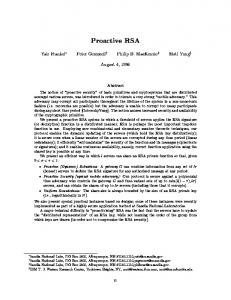
track with same speed as that in normal handoff experiment. The fast-handoff happens at time 51.03s, introducing only a 47ms IAT for one packet on downlink. We repeat the experiment with other tracks for movement, and observe at most one downlink packet drop during handoff and no uplink packet loss without IAPP involved. IAT(Inter-arrival Time) of Packets(ms)
locations marked with x are the places we measured the transmission rates and RSSI. The solid boxes in the figure denote the pillars(occupy 1m2 for each) in the building. Note that the APs at location A and E are configured to the same SSID, and there are six other APs in this area but belonging to another network with different SSID.
200
IAT handoff 150
100
50
0 35
40
45
50
55
60
65
Time(s)
Figure 10. Fast Handoff with proactive scan
Figure 8. Map and device locations for handoff experiment
IAT(Inter-arrival Time) of Packets(ms)
A. Service interuption during handoff As we’ve mentioned, the latency introduced during handoff results in service interruption, deteriorating the performance significantly. To measure the impact to real time application, we developed a VoIP application using GSM 06.10 codec with the frame interval at 20ms equally and packet size at 33bytes. A VoIP connection is setup between STA-201 and STA-206. We measure the IAT(Inter-arrival time) of packets at both ends. 2000
IAT handoff 1500
1000
500
0 45
Figure 11. Fast Handoff procedure 50
55
60
65
70
One fast-handoff procedure is shown in Figure.11. We mark the time that proactive scan has been triggered as 0. The proactive scan in this procedure is stopped at 875ms as the fast handoff is triggered. It takes 8.3ms to finish connecting the new AP without IAPP involved. So the total service interruption time in our fast handoff is 8.3ms. If one packet happens to arrival to the old AP during this period, then it results in one packet loss. Since the packet interval is 20ms in our experiment, at most one packet will be dropped. Note that the 875ms proactive scan time depends on the user moving track and speed. In our experiment, we observe it ranges from hundreds of milliseconds to several seconds.
75
Time(s)
Figure 9. Handoff on standard Windows XP Atheros 5212 driver
The performance of a normal handoff using commercial Atheros 5212 driver on Window XP is shown in Figure.9. The driver starts handoff and scans other channel at time 58.68s and its scan taking about 8s to scan all the channels since it’s a combo a/g/b NIC (and there are 28 channels to scan). The smallest scan time for this driver measured in experiment is about 3s. However, the service interruption time is more than the scanning time. In Figure 9, we observe that before handoff triggers, the service has already been very poor after time 55s. The conservative trigger for handoff also enlarges the total service interruption time for normal handoff. The measured IAT of packets during our fast handoff approach is shown in Figure.10, where we walk on the same
B. Overhead introduced by proactive scan During proactive scan, the ongoing application is affected slightly due to the scanning operation to other channels. To
756
This full text paper was peer reviewed at the direction of IEEE Communications Society subject matter experts for publication in the IEEE INFOCOM 2007 proceedings.
evaluate the overhead introduced by proactive scan, we force the proactive scan continuously enabled, and measure the performance under different scan interval. For VoIP like application, the performance is judged by the IAT(inter-arrival time) of packets since it denotes the jitter variation. The sender(STA-206) generates UDP packets at 50packets/s spaced at 20ms equally to STA-201 through AP, and we measure the CDF (cumulative distribution function) of IAT of packets received at the station side. Figure.12 gives the measured results for continuous scan interval at 100-300ms, and when scan is disabled. The averaged IAT is 20ms in measurement under all scan interval setups. We observe 300ms interval introduces ignorable impact to packet IAT. In addition, the default 200ms interval introduces only 5% packet interarrival time larger than 25ms, with the maximal value at 35ms. We also try our VoIP application with continuous scanning and can not detect any impact to the voice quality of VoIP application during the experiment for all settings.
VIII. CONCLUSIONS In this paper, we present Proactive Scan, a fast handoff solution to support real time services, e.g., VoIP, over WLAN. It is a software module residing at an 802.11 NIC (network interface card) driver to make intelligent handoff decisions. Proactive Scan decouples the time-consuming channel scanning from the actual handoff. The scanning is performed proactively without human-detectable interruptions to ongoing traffic. Therefore, when the handoff is really triggered, the station may already have all updated information and the service disruption time is greatly reduced. Moreover, we develop sophisticated triggers for both proactive scanning and actual handoff. Our triggers address the link asymmetry which widely exists in WLAN and have much better accuracy for scanning and handoff decisions. We have implemented Proactive Scan and our experimental study shows that the handoff latency with Proactive Scan is less than 10ms. This proves that a client-only software-only solution for fast handoff in 802.11 WLAN is achievable.
1
REFERENCES CDF of packets
0.8
[1] [2]
0.6
[3] 0.4
100ms 200ms 300ms No scan
0.2
0 0
5
10
15
20
25
30
35
40
[4] [5]
45
Packet Inter-arrival Time(ms)
Figure 12. CDF of packet interarrival time versus proactive scan interval
[6]
For ftp or web like TCP traffic, one concern for proactive scan is the overhead introduced by scanning may affect TCP’s self clocking and deteriorate the performance. To evaluate the impact to reliable transmission, we use a greed ftp connection between STA-201 and STA-206. TCP throughput is sensitive to the link rate, which is adjusted by rate adaptation. So we disable the auto-rate and test the overhead under fixed link rate for comparison. The TCP throughputs for uplink and downlink are measured respectively, which is shown in Table.3. We use the ratio of obtained TCP throughput under different proactive scan interval over that with no scan to quantify the overhead introduced by scan, so larger ratio means smaller overhead. With the default 200ms scan interval, the overhead introduced to greed TCP traffic is about 10%. When link rate is smaller, e.g., 12Mbps compared with 54Mbps, the packet transmission time becomes longer while the time overhead introduced by scan does not change, so the throughput ratio becomes larger. Link Rate
[7] [8] [9] [10]
[11]
[12] [13] [14] [15]
Interval TCP throughput (Mbps)
Traffic 54Mbps Upload Download 12Mbps Upload Download
100ms
200ms
300ms
No scan
[16]
17.3(76%) 20.57(91%) 21.43(94.9%) 22.57 14.52(64%) 18.88(84%) 20.32(90%) 22.69 6.48(77%) 7.90(94%) 8.37(99.7%) 8.39 6.7(80%) 7.8(93%) 8.33(99.6%) 8.36
[17] [18] [19]
Table3. TCP throughput versus link rate and proactive scan interval
[20]
757
IEEE standard for Wireless LAN Medium Access Control (MAC) and Physical Layer (PHY) specifications, ISO/IEC 8802-11:1999(E), 1999. B.P. Crow and J.G. Kim. IEEE 802.11 Wireless Local Area Networks, IEEE Comm., Sept. 1997. IEEE Trial-Use Recommended Practice for Multi-Vendor Access Point Interoperability via an Inter-Access Point Protocol Across Distribution Systems Supporting IEEE 802.11™ Operation, IEEE Std 802.11-2003 Part 11: Wireless Medium Access Control (MAC) and physical layer (PHY) specifications: Amendment 8: Fast BSS Transition, IEEE P802.11r/D0.09, September 2005 Part 11: Wireless Medium Access Control (MAC) 10 and physical layer (PHY) specifications 11 Amendment 7: Radio Resource Measurement, IEEE P802.11k/D2.0, February 2005 A. Mishra, M. Shin, and W. Arbaugh, An Empirical Analysis of the IEEE 802.11 MAC layer Handoff Process. ACM Computer Communications Review, vol. 33, no. 2, Apr. 2003. M.S. Bargh, R.J. Hulsebosch, E.H. Eertink, etal., Fast Authentication Methods for Handovers between IEEE 802.11 Wireless LANs, WMASH’04 V.Mhatre, K.Papagiannaki, Using Smart Triggers for Improved User Performance in 802.11 Wireless Networks, Mobisys 2006 A. Mishra, M.Shin,W.A.Arbaush, Context caching using neighbor graphs for fast handoffs in a wireless network, IEEE Infocom 2004 H.Kim, S.Park, C.Park, J.Kim, and S.Ko, Selective Channel Scanning for Fast Handoff in Wireless LAN using Neighbor Graph, ITCCSCC2004 S.Pack, H.Jung, T.Kwon, Y.Choi, SNC: A Selective Neighbor Caching Scheme for Fast Handoff in IEEE 802.11 Wireless Networks, Mobile Computing and Communications Review, Volume 9, Number 4 I.Ramani and SSavage, SyncScan: Practical Fast Handoff for 802.11 Infrastructure Networks, IEEE Infocom 2005 Cisco Fast secure roaming, http://www.cisco.com A. Kamerman and L. Monteban. WaveLAN II: A high-performance wireless LAN for the unlicensed band. Bell Labs Technical Journal, pages 118-133, 1997. G.Holland, N.Vaidya, P.Bahl, A Rate-Adaptive MAC Protocol for Multi-Hop Wireless Networks, In Mobicom 2001 B.Sagdehi, V.Kanodia, A.Sabharwal, and E.knightly. Opportunistic media access for multirate ad hoc networks, in Mobicom 2002 V.Brik, A.Mishra, S.Banerjee, Eliminating handoff latencies in 802.11 WLANs using Multiple Radios: Applications, Experience, and Evaluation, IMC 2005 S.Waharte, K.Ritzenthaler and R.Boutaba, Selective Active Scanning for Fast Handoff in WLAN Using Sensor Networks, IEEE MWCN 2004 R.Chandra, P.Bahl, P.Bahl, MultiNet: Connecting to Multiple IEEE 802.11 Networks Using a Single Wireless Card, INFOCOM 2004 NS2, http://www.isi.edu/nsnam/ns/