Probabilistic & Reliability-based Health Monitoring Strategies for High-Speed Naval Vessels Office of Naval Research (ONR) Contract Number: N00014-09-1-0567
FINAL REPORT Jerome P. Lynch, Ph.D., University of Michigan (PI) Kincho H. Law, Ph.D., Stanford University (Co-PI) Sean O'Connor, University of Michigan
Date of Report: January 1, 2012
Points of Contact: Jerome P. Lynch, Ph.D. Associate Professor Department of Civil and Environmental Engineering Department of Electrical Engineering and Computer Science 2380 G. G. Brown Building Ann Arbor, MI 48109-2125 (734)615-5290 jerlynch @umich.edu
Kincho H. Law, PhD Professor Department of Civil and Environmental Engineering Room 277A, Y2E2 Building 473 Via Ortega Stanford University Stanford, CA 94305-4020 (650)725-3154
[email protected]
DEFENSE TECHNICAL INFORMATION CENTER
liMtdäkUmhmäv DTICfhas determined on j /////C^that this Technical Document has the Distribution Statement checked below. The current distribution for this document can be found in the DTICf Technical Report Database.
w
DISTRIBUTION STATEMENT A. Approved for public release; distribution is unlimited.
] © COPYRIGHTED. U.S. Government or Federal Rights License. All other rights and uses except those permitted by copyright law are reserved by the copyright owner.
|
| DISTRIBUTION STATEMENT B. Distribution authorized to U.S. Government agencies only (fill in reason) (date of determination). Other requests for this document shall be referred to (insert controlling DoD office). ] DISTRIBUTION STATEMENT C. Distribution authorized to U.S. Government Agencies and their contractors (fill in reason) (date determination). Other requests for this document shall be referred to (insert controlling DoD office). ] DISTRIBUTION STATEMENT D. Distribution authorized to the Department of Defense and U.S. DoD contractors only (fill in reason) (date of determination). Other requests shall be referred to (insert controlling DoD office). ] DISTRIBUTION STATEMENT E. Distribution authorized to DoD Components only (fill in reason) (date of determination). Other requests shall be referred to (insert controlling DoD office). ] DISTRIBUTION STATEMENT F. Further dissemination only as directed by (insert controlling DoD office) (date of determination) or higher DoD authority. Distribution Statement F is also used when a document does not contain a distribution statement and no distribution statement can be determined. ] DISTRIBUTION STATEMENT X. Distribution authorized to U.S. Government Agencies and private individuals or enterprises eligible to obtain export-controlled technical data in accordance with DoDD 5230.25; (date of determination). DoD Controlling Office is (insert controlling DoD office).
Form Approved OMB No. 0704-0188
REPORT DOCUMENTATION PAGE
The public reporting burden for this collection of information is estimated to average 1 hour per response, including the time for reviewing instructions, searching existing data sources, gathering and maintaining the data needed, and completing and reviewing the collection of information. Send comments regarding this burden estimate or any other aspect of this collection of information, including suggestions for reducing the burden, to Department of Defense, Washington Headquarters Services, Directorate for Information Operations and Reports (0704-0188), 1215 Jefferson Davis Highway, Suite 1204, Arlington, VA 22202-4302. Respondents should be aware that notwithstanding any other provision of law, no person shall be subject to any penalty for failing to comply with a collection of information if it does not display a currently valid OMB control number.
PLEASE DO NOT RETURN YOUR FORM TO THE ABOVE ADDRESS. REPORT DATE (DD-MM-YYYY)
DATES COVERED (From - To) April 1,2009-March 1,2010
2. REPORT TYPE
Final Technical Report
1-01-2012 4. TITLE AND SUBTITLE
5a. CONTRACT NUMBER
Probabilistic & Reliability-based Health Monitoring Strategies for High-Speed Naval Vessels
5b. GRANT NUMBER
N00014-09-1-0567
5c. PROGRAM ELEMENT NUMBER
5d. PROJECT NUMBER
6. AUTHOR(S)
Jerome P. Lynch, Ph.D. Kincho H. Law, Ph.D. Sean O'Connor
5e. TASK NUMBER
5f. WORK UNIT NUMBER
7. PERFORMING ORGANIZATION NAME(S) AND ADDRESS(ES)
University of Michigan 2380 G G Brown Building Ann Arbor, MI 48109-2125
8. PERFORMING ORGANIZATION REPORT NUMBER
10. SPONSOR/MONITORS ACRONYM(S)
9. SPONSORING/MONITORING AGENCY NAME(S) AND ADDRESS(ES)
Office of Naval Research Attn: Paul Hess 875 North Randolph Street Arlington, VA 22203-1995
ONR 11. SPONSOR/MONITORS REPORT NUMBER(S)
12. DISTRIBUTION/AVAILABILITY STATEMENT
13. SUPPLEMENTARY NOTES
^O/^OSO^CJ3/ 14. ABSTRACT
In this project, a strategy is proposed for fatigue life estimation of a ship hull using a wireless sensor network installed in the hull for autonomous health monitoring. First, a rainflow counting algorithm is implemented as a continuous time-domain approach to fatigue estimation. Cycles are defined by a rainflow counting procedure and are kept on-board the wireless sensing unit in a histogram structure for long-term storage. Fatigue damage is accumulated by the Palmgren-Miner linear summation method. Second, a statistical approach called the Dirlik procedure is used which relies on spectral moments of the stress-time history power spectral density (PSD) function. The Dirlik procedure outputs a probability density function (PDF) of stress ranges, tailored to resemble the rainflow counting results. The PDF is converted to damage using an S-N curve and again accumulated by the Palmgren-Miner method. Experimental tests are conducted on an aluminum hull stiffened element specimen as part of the Monitored Aluminum Hull Integrity (MAHI) test program to verify the embedded fatigue life estimation procedures. 15. SUBJECT TERMS
16. SECURITY CLASSIFICATION OF: a. REPORT
b. ABSTRACT
c. THIS PAGE
17. LIMITATION OF ABSTRACT
18. NUMBER 19a. NAME OF RESPONSIBLE PERSON OF Jerome P. Lynch, Ph.D. PAGES 19b. TELEPHONE NUMBER (Include area code)
734-615-5290 Standard Form 298 (Rev. 8/98) Prescribed by ANSI Std. Z39.18
Table of Contents Executive Summary
3
Acknowledgement
4
1. Introduction
5
2. Technical Objectives
5
3. Theoretical Background and Algorithms
6
3.1. Rain Flow Peak Extraction and Miner's Rule for Fatigue Estimation
6
3.2. Spectral Methods for Fatigue Estimation
10
4. Experimental Validation of the Embedded Fatigue Estimation Algorithms
13
4.1. Implementation in the Narada Wireless Sensor Node
13
4.2. Aluminum Bar Specimens under Uniaxial Tensile Loading
16
4.3. Validation on the Monitored Aluminum Hull Integrity (MAHI) Phase I Specimen
21
5. Summary and Future Direction
26
References
27
Page 2 of29
Executive Summary As the U.S. Navy aggressively pursues the design of high-speed aluminum vessels for littoral combat operations, there is a growing need for on-board hull monitoring systems capable of detecting hull deterioration and damage. In particular, fatigue damage is anticipated due to the combination of non-traditional hull forms and demanding seaway loads. Fatigue is an accumulated degradation process that occurs under cyclic loading, eventually inducing cracking at stress concentration points. In this project, a strategy is proposed for fatigue life estimation of a ship hull using a wireless sensor network installed in the hull for autonomous health monitoring. Specifically, the computation and storage capabilities of each wireless sensing unit are leveraged to process large, continuous amounts of raw strain gage data for fatigue life information, thereby presenting the user with very little data, yet very meaningful decision making information. First, a rainflow counting algorithm is implemented as a continuous timedomain approach to fatigue estimation. A peak picking algorithm reduces time history data to a minimum set of data points that are needed for fatigue analysis. Cycles are defined by a rainflow counting procedure and are kept on-board the wireless sensing unit in a histogram structure for long-term storage. Fatigue damage is accumulated by the Palmgren-Miner linear summation method. Second, a statistical approach called the Dirlik procedure is used which relies on spectral moments of the stress-time history power spectral density (PSD) function. The main motivation for this approach is to use a few statistical parameters from the power spectrum to estimate fatigue life rather than doing the continuous collecting and processing that is conducted in the rainflow procedure. The Dirlik procedure outputs a probability density function (PDF) of stress ranges, tailored to resemble the rainflow counting results. The PDF is converted to damage using an S-N curve and again accumulated by the Palmgren-Miner method. Damage results are kept on-board for long-term storage awaiting user query. Communication of results is done only by request, dramatically reducing the power consumption in the wireless sensing network. Experimental tests are conducted on an aluminum hull stiffened element specimen as part of the Monitored Aluminum Hull Integrity (MAHI) test program to verify the embedded fatigue life estimation procedures. Testing is carried out at the Naval Surface Warfare Center-Carderock Division (NSWCCD) Fatigue Testing Laboratory. Among the key objectives of the MAHI test program is the demonstration and evaluation of SHM technologies. A tethered strain gage monitoring system with 16 channels is employed for laboratory data collection. A network of Narada wireless sensor units is used to collect multiple strain gage channels performing continuous data collection as well as the embedded rainflow and Dirlik fatigue estimation procedures. Strong agreement is found between the Narada and NSWCCD data. Furthermore, the accuracy of the embedded fatigue estimation algorithms is confirmed.
Page 3 of29
Acknowledgement The authors would like to acknowledge the support offered by the Office of Naval Research under Contract Number N00014-09-1-0567 and N00014-10-1-0613 awarded to University of Michigan and N00014-10-1-0384 awarded to Stanford University. The authors also would like to thank Dr. Liming W. Salvino of ONR Global and Edward Devine of Naval Surface Warfare Center (NSWC) - Carderock Division for their contributions to this research. In addition, active collaborations and guidance on aluminum naval ship structures from Thomas Brady and David Kihl of the Naval Surface Warfare Center - Carderock Division are very much appreciated. Last but not least, the advice and suggestions offered by Dr. Paul Hess of ONR throughout the project are gratefully acknowledged.
Page 4 of 29
1. Introduction In recent years, the need for high-speed littoral combat ships (LCS) has driven U.S. Navy interest in aluminum hulls of unconventional design (e.g., multi-hull catamaran style ships). For example, the Joint High-Speed Vehicle (JHSV) and Littoral Combat Ship (LCS) programs are examples of major ship design and procurement programs instituted by the U.S. Navy (Hess 2007). While aluminum allows the ship weight to be dramatically reduced as compared to the use of steel, aluminum introduces a number of significant challenges for long-term ship operation and management (O&M). Foremost among those concerns is fatigue cracking in the aluminum hull. Fatigue is predicted to be a serious O&M issue due to a general lack of design and analytical methods for aluminum hulls, especially hulls that will experience the excessive seaway loads anticipated for LCS (Tveiten, et al. 2007). Since the mid-1950's, the Navy has utilized aluminum in the design and construction of the deckhouses of their steel destroyer-class ships (Sielski 2007). However, fatigue issues have emerged with these deckhouses, especially the rate of growth of fatigue cracks resulting in severe deckhouse damage in extreme sea conditions. As the Navy moves toward aluminum for the construction of LCS hulls, it is interested in the adoption of long-term hull monitoring systems that can closely monitor hull responses to seaway loads. The benefits of hull monitoring are enormous. First, hull response data can be used to validate design assumptions leading to improvements in the design of future vessels. Second, hull response data would be integral to the health assessment of the ship (i.e., structural health monitoring (SHM)) and guide O&M decision making of the port engineer. The early detection of hull damage and/or deterioration allows the Navy to resolve structural issues in a more cost-effective and timely manner leading to dramatic reductions in the total life-time cost of ownership of a naval vessel. Researchers have begun to investigate the development of structural health monitoring (SHM) systems for high-performance ships (Farrar, et al. 2009). Any SHM system designed and deployed for aluminum hull ships must exhibit the ability to detect the onset of fatigue in the hull components. This project explores data-driven algorithms that can be autonomously executed by the hull monitoring system to identify fatigue damage. Known hull hot-spots (e.g., base plates, heat affected zones near welds) are often instrumented with strain gages to record the hull response under cyclic wave loading (Bachman, et al. 2007). The strain gages would normally be interfaced to a wired hull monitoring system. However, in recent years, wireless telemetry has been explored in the shipboard environment because of their potential to eliminate monitoring system wires (Lynch, et al. 2009). The reported benefits of wireless hull monitoring include lower installation costs and the installation of a larger number of sensors in the hull. Regardless of the type of hull monitoring system employed (e.g., wired or wireless), a scalable approach to processing hull response data for an accurate assessment of the hull health is still lacking. Until such algorithms are shown accurate and reliable in the detection of hull deterioration, acceptance of SHM in the naval engineering community will be limited.
2. Technical Objectives This project explores data-driven algorithms that can be autonomously executed by the hull monitoring system to specifically identify fatigue damage. The approach to fatigue analysis depends on use of hull strain time history data to automate the process of damage detection. Time- and frequency-domain algorithms are adopted to continuously and autonomously count strain peaks in the recorded strain time histories. Using peak amplitude strains (S) and the Page 5 of29
Figure 1: Rainflow cycle analysis via closed loop identification
accumulated number of peaks (N), the Palmgren-Miner rule and the appropriate S-N curve for the ship's aluminum alloy are selected to roughly track the fatigue life of the instrumented hull detail. The selection of these methods of tracking the fatigue life of hull components is motivated by their computational simplicity. In particular, these fatigue estimation algorithms are embedded into the computational cores of Narada wireless sensor nodes; Narada has been previously validated for hull monitoring on the FSF-1 SeaFighter (Lynch, et al. 2009). The specific project objectives are: • Rain flow assessment of strain time histories will be implemented along with Miner's rule in the computational core of a wireless sensor for fatigue monitoring of aluminum components. Experimental validation will be performed on aluminum coupon specimens loaded under uniaxial load. • Spectral methods to peak extraction will also be implemented with Miner's rule in the computational cores of a wireless sensor. Again, experimental validation will be conducted using aluminum coupons loaded under uniaxial load. • Third, the embedded fatigue analysis will be validated experimentally on complex aluminum hull connections at NSWC-Carderock.
3. Theoretical Background and Algorithms 3.1 Rain Flow Peak Extraction and Miner's Rule for Fatigue Estimation
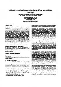
Fatigue life monitoring begins by identifying cycles within a complex load time history. A number of cycle counting methods are used to reduce irregular load histories into a collection of constant amplitude events such as rainflow counting (primarily used herein), range-pair counting, and racetrack counting. Rainflow cycle counting has shown to be among the superior methods for cycle counting of irregular loads. In the rainflow method, cycles are identified in a manner in which closed hysteresis loops are identified from the stress-strain response of a material subject to cyclic loading. As shown in Fig. 1, closed hysteresis loops can be identified from the strainPage 6 of 29
Cycle Histogram
c|\X
— Plastic Strain
r- Of'/E \2X
y Elastic Strain
\ \
ET——i>^ 1 ~"^""~"
2N,
Strain Amplitude
Figure 2: Histogram of cycle accumulation
Figure 3: Strain-life curve
time history shown. Ranges A-D, B-C, E-F, and G-H, would represent cycles counted under rainflow counting techniques. Rainflow counting, however, is originally intended to be carried out once the entire strain history is known, since counting starts and ends at the maximum peak or valley. Due to the limited memory available in wireless sensors, it is not possible to wait until the entire load history has been realized before fatigue accumulation can be calculated. Rather, the 'one-pass' rainflow counting algorithm can be alternatively used since it does not require the full time history record. This method, which was used for embedment in this study, is a vectorbased counting algorithm first demonstrated by Downing, et al. (1976) and later modified by Okamura, et al. (1979) to account for half cycles. The embedded rainflow counting algorithm starts by arranging sampled strain time history measurements into a single vector. From the set of strain data, peak and valley points inherent in cyclic measurements are identified and stored. The typical rainflow counting procedure is then performed on the set of peaks and valleys, identifying closed hysteresis loops and logging those ranges as cycles. For each cycle, both the strain amplitude and mean strain are recorded. This rainflow counting procedure identifies the same cycles as the traditional rainflow procedure that uses the entire strain time history. This fact makes the 'one-pass' rainflow counting procedure very attractive for continuous real-time monitoring of fatigue life using wireless sensors. The 'one-pass' rainflow counting technique can be operated in a real-time manner for continuous monitoring of fatigue life. The compression of a strain time history from sampled points to cycles though, is not enough to monitor fatigue in the long-term. Further data compression is realized by accumulating identified cycles of mean and amplitude into a histogram similar to the one shown in Fig. 2. A fixed size histogram allows for a priori allocation of the available memory integrated with the wireless sensor, allowing for the near perpetual accumulation of fatigue cycles and thus continuous "real-time" fatigue life monitoring. Considerations of bin sizing in the mean and amplitude axes will be of importance in terms of mean and amplitude accuracy, as well as in terms of the scarce memory consumed. Strain-life methods which account for mean strain effects are used in this project to predict fatigue life. First, the total strain amplitude can be expressed as the sum of an elastic strain amplitude and a plastic strain amplitude, each represented linearly against cycles to failure on a
Page 7 of 29
log-log plot. Total strain amplitude versus cycles to failure, Nf, before mean stress (or mean strain) correction is written as: — =f(2Nf)b+ef(2Nfy where:
V>
— = strain amplitude af' = fatigue strength coefficient E = modulus of elasticity 2Nf = reversals to failure e/ = fatigue ductility coefficient b = fatigue strength exponent c = fatigue ductility exponent
The constants b and c represent the slopes of the elastic and plastic strain. Similarly, aj- and e/ are the y-axis intercepts of the elastic and plastic strain curves in Fig. 3. Eq. (1) is applicable if dealing with full cycles with zero mean strain. However, several researchers have proposed modifications to the strain-life relationship of Eq. (1) to account for mean stress effects including Morrow (1968) and Manson and Halford (1981). These relations all have their own advantages, but require the mean stress in order to evaluate the number of cycles to failure. A modification to the strain-life relation using mean strain instead of mean stress would be better because strain is measured and not stress. The need to track stress-strain around a hysteresis curve to determine mean stress is taken out of the picture, making the embedded process easier to implement. One such empirical relationship between total strain range, Ae, and cycles to failure is adopted here. This empirical relationship which accounts for mean strain instead of mean stress is written as: 2(l-fi)C/
Ae m
a
(2) 1/a
[(ANf - 1)(1 - R) + (2)«]
where:
R = emin/emax if \emax\ > \e mini " ^£
^max/^min " \^max\ "^ F —
^max ~ Emin
Here, a is equal to -lie. The fatigue ductility coefficient,^', fatigue strength exponent, b, and fatigue ductility exponent, c, determined for the strain-life relationship are used both directly and in computing the material constant, a. These parameters are best evaluated by performing cyclic testing in the laboratory. When fatigue data is not available or easily obtained, these parameters can be estimated from static properties or by using other estimation methods. In this study, the empirical fatigue law of Eq. (2) will be used. To estimate the model parameters (fatigue ductility coefficient, e/, fatigue ductility exponent, c, and fatigue strength exponent, b), the uniform material law by Bäumel and Seeger (1990) is used. For aluminum and titanium alloys, the strain-life equation is estimated as y = 1.67
95
Y(2A//)-°
+ 035(2Nf)-°69
Page 8 of29
(3)
where:
ab = yield stress.
While Eq. (3) will not be used, one can however extract the fatigue ductility coefficient, e/, fatigue ductility exponent, c, and fatigue strength exponent, b from it. With knowledge of these constants, the material constant, a, can be estimated and Eq. (2) can be written in its final form as: Ae =
2(l-/?)0.35
(4)
[(4fy - 1)(1 - R)-°A + (2)-°-4]1/-°-4
In this form, the mean strains and strain amplitudes obtained through rainflow counting are sufficient for determining the fatigue life, Nf, of an instrumented component. Although it is possible to embed a mean stress procedure, it will require more work for the wireless sensor and may be unnecessary as the prediction proposed in Eq. (4) has been shown to compare extremely well with data received from alloys tested under a variety of different tensile and compressive mean strains (Collins 1981). The fatigue life corresponding to each cycle is an indication of the amount of damage imposed on the material due to that specific cycle. In this way, one can start to accumulate and monitor damage. The damage summation of each cycle is done using the Palmgren-Miner linear damage hypothesis originally proposed by Palmgren (1924) and later modified by Miner (1945). The Palmgren-Miner rule is written as: n.
where:
(5)
D = accumulated damage k = total number of cycles in a loading spectrum i = ith applied stress/strain level Tij = number of cycles at stress/strain level i Nt = fatigue life at stress/strain level i
This method implies that failure occurs when the summation of cycle ratios, n/Nj, is equal to 1. It should be noted that by using strain-life methods, the initial cracking is predicted instead of complete failure. Further monitoring of fatigue damage (i.e., after the initiation of cracking) requires crack propagation methods which are beyond the scope of this project. The value residing in each bin of the accumulated cycle histogram represents the number of cycles at a specific strain amplitude and mean. The position of each bin determines the fatigue life of that particular bin, since it represents the strain amplitude and mean strain required for the strain-life relation. In the embedded implementation, cycles incurring damage below a specified threshold result in their elimination from the analysis. Signal noise will generate high amounts of low amplitude cycles, which when accumulated over an excessive amount of time may falsely contribute to the expended life of the material. Although certain materials have no defined fatigue limit, this liberty is assumed safe as noise level amplitudes are far below reasonably Page 9 of29
assumed estimations for fatigue limits of these materials. It is important to use damage as the parameter for which cycles are counted or eliminated from analysis. Very small amplitude cycles at very high mean stress may result in relevant fatigue damage, and should not be eliminated from analysis. 3.2 Spectral Methods for Fatigue Estimation
A frequency domain approach to cycle identification for estimation of fatigue accumulation is also explored as an alternative to the proposed rainflow methods. Since many loading environments arise as stochastic processes (e.g., live loads, wind, waves), it is appropriate to use power spectral density (PSD) as a statistical function describing operational loads. The main motivation for the frequency domain approach is to use only a few statistical parameters deduced from a power spectrum to estimate fatigue life rather than doing continuous cycle counting in the time domain as is the case in rainflow counting methods. Many results exist for the case of narrow band stationary and ergodic random signals, especially those having a Rayleigh stress range distribution; however, one would like to have a procedure capable of handling wide band loading as well (Kirkby 1966). The Dirlik (1985) approach used here provides a closed form expression linking any given power spectral density to a probability density function of rainflow ranges when the random process is stationary and ergodic. The Dirlik procedure uses a Monte Carlo approach to generate stress time histories from various PSD shapes. Time domain rainflow counting is performed and a probability density function of rainflow ranges is linked to the corresponding PSD shape. Dirlik's solution is empirically derived by fitting rainflow range distributions to simulated data and is technically restricted to Gaussian processes. Theoretically based solutions exist under certain conditions, (e.g., Bishop and Sherrat (1990)) but Dirlik's method remains among the most frequently employed techniques due to its simplicity and due to its sufficient level of accuracy under required conditions. The bulk of signal processing in Dirlik's method lies in the Fourier transform used to convert time-history strain data to the frequency-domain. A fast Fourier transform (FFT) is used to determine the power spectral density (PSD) function of strain data collected. The PSD is the base of all calculations in the analytical procedure. Specifically of interest are the spectral moments, where the n'h moment is defined as: m
if
n= — \ ü)nG(u>)d(i)
(6)
0
or, in the case of a discrete PSD, can be visually observed in Fig.4 and written as mn = J fnG(f)df f=o
Many probabilistic characteristics of the signal arise from these moments. In 1945, Rice (1945) provided the relationship for the number of upward zero crossings and peaks per second based solely on spectral moments, paving the way for a fatigue life estimation based on power spectral density. The relations are seen below as:
Page 10 of 29
„ = Y^raodf
Figure 4: Spectral moments of the strain/stress PDF
Expected number of zero crossings per unit time, A0: j 'to —
£
(8)
Expected number of peaks per unit time, ß: m4
(9)
Irregularity factor, y: m2
(10)
Irregularity factor is the measure of the expected ratio of zero-crossings to peaks, approaching zero for the wide band case and one for the narrow band case. Other important characteristics arising from the spectral moments include the root mean square (RMS), ox