International Journal of Security and Its Applications Vol. 7, No. 3, May, 2013
Probability-based Tamper Detection Scheme for BTC-compressed Images Based on Quantization Levels Modification Yu-Chen Hu1, Chun-Chi Lo2, Chang-Ming Wu3, Wu-Lin Chen1 and Chia-Hsien Wen1 1
Department of Computer Science and Information Management, Providence University, 200 Chung Chi Rd., Taichung 43301, Taiwan 2 Department of Computer Science and Information Engineering, Providence University, 200 Chung Chi Rd., Taichung 43301, Taiwan 3 Department of Electronic Engineering, Chung Yuan Christian University Chung-Li 32023, Taiwan
[email protected],
[email protected],
[email protected],
[email protected],
[email protected] Abstract To protect the image integrity of the compressed images for block truncation coding (BTC), an image authentication scheme is proposed in this paper. In this scheme, the authentication data of each compressed image block is generated from the random value induced by the predefined random seed. The size of the authentication data can be selected according to the user’s requirement. Then, the authenticaiton data is embedded into the difference value between the quantization levels of each BTC-compressed image block. The experimental results reveal that the proposed scheme performs well in terms of detection precision and the embedded image quality. Keywords: image authentication, tamper detection, block truncation coding, fragile watermarking
1. Introduction Data communication over the Internet has become more and more popular due to the rapid and continuous development of the networking technologies. Among the transmission data, digital images are the popularly used medium. Usually, the compressed digital images are used because the raw image files require a lot of storage cost. Typically, the image compression techniques can be classified into two categories: lossy compression and lossless compression. The lossy compression techniques are often used to compress general-purpose images. Some lossy image coding techniques, such as JPEG, JPEG 2000, block truncation coding (BTC) [1-5], vector quantization, color image quantization, and sub-band coding, fractal coding, had been proposed. The lossless image coding techniques are often used to process special-purpose images, such as the military images and the medical images. Some lossless image coding techniques, such as Huffman coding, arithmetic coding, and JPEG/LS, had been proposed. The research issue towards the image integrity protection becomes more and more important in recent decades because digital images can be easily copied and modified by using the image processing software. A traditional cryptography approach can only be employed to protect the security of digital data. It cannot be employed for the protection of image integrity. When one cryptograph scheme, such as RSA [6], AES, MD5, or RSA, is employed to process the digital image, the encrypted data of the digital image is meaningless.
11
International Journal of Security and Its Applications Vol. 7, No. 3, May, 2013
In addition, any changes from the encrypted data can be easily detected. However, the tampered areas of the image cannot be located by using the cryptograph approach. The image authentication approach [7] for image integrity protection had thus been proposed. Basically, the image authentication schemes can be classified into two categories: signature-based schemes [8-11] and fragile watermark-based schemes [12-20]. In a signature-based scheme, the given image is processed by using the hash function and the hashed result is encrypted by using the public key cryptosystem to generate the digital signature. Then, the digital signature of the image to be protected is stored in a trust third party. When the image is to be authenticated, the digital signature is extracted from the trust third party and it is compared to the other signature that is generated from the image to detect the tampered areas. In a fragile watermark-based scheme, the watermark is embedded into the image to be protected. The watermark is often generated by using either the image features extracted from the given image or the random values induced by the selected random nubmer seed. When the image is to be authenticated, the watermark is extracted from the image to detect the tampered areas. The general requirements of a fragile watermark scheme are listed in the following: (1)Imperceptibility: Any modifications to the image cannot be perceived by the human’s eyes after the watermark is embedded. (2)Without resorting to the original image: The original image need not be involved in the tamper detection process. (3)Locating tempered areas: The scheme should locate the tempered areas or identify the type of image attack. Till now, several fragile watermark schemes had been introduced. Lin and Chang proposed a semi-fragile watermarking scheme [12] which can be resistant to lossy compression for JPEG images. Wong and Memon proposed the secret and public key image watermarking schemes [13] for image authentication and ownership verification in 2001. Lie, et al., [14] proposed a compression-domain scheme that provides dual protection for JPEG images in 2006. Lee and Lin proposed the dual watermark for both image tamper detection and image recovery [15] in 2008. Ahmed and Siyal proposed an image authentication scheme [16] based on the hash function in 2010. Qi and Xin proposed a quantization-based semi-fragile watermarking scheme [17] for image content authentication in 2011. Chung and Hu proposed an adaptive image authentication scheme for VQ compressed images in 2011 [18]. In 2013, Hu et al. proposed a novel tamper detection scheme [19] for the compressed images of BTC. In this scheme, the authentication codes of the image blocks are generated from the quantization levels. Multiple copies of the authentication codes are embedded into the bit maps based on the block permutation. In addition, a joint image compressed and image authentication technique had been proposed [20] for the compressed images of BTC. In this paper, we design an image authentication scheme for the BTC-compressed images. The proposed scheme intends to improve the image quality of the embedded quality while keeping good detection precision. The rest of this paper is organized as follows. We will review some block truncation coding schemes in Section 2. Section 3 will present the proposed scheme. The experimental results will be discussed in Section 4. Finally, some discussions and conclusions will be given in Section 5.
2. Review on Block Truncation Coding The block truncation coding (BTC) scheme [1-2] was proposed by Delp and Ritcell in 1979 for grayscale image compression. It is also called the moment-preserving block
12
International Journal of Security and Its Applications Vol. 7, No. 3, May, 2013
truncation coding (MPBTC) scheme because it preserves the first and second moments of image blocks. The absolute moment block truncation coding (AMBTC) [3] had been proposed to preserve the sample mean and the sample first absolute central moment in 1984. Basically, the BTC scheme has very simple image encoding/decoding procedures and requires little computational complexity. It can be applied to the compression of monochrome images, moving imagery, color imagery [3], and graphics. The main problem of the BTC scheme is that its compression ratio is low. From the literature, some methods [4-5] that aim to raise the compression ratio of BTC had been proposed. In this section, the moment preserving block truncation coding scheme [1] will be first described. Next, the absolute moment block truncation coding scheme [3] will be introduced. 2.1. Moment preservation block truncation coding The moment preservation block truncation coding scheme consists of the image encoding and the image decoding procedures. In the image encoding procedure, each grayscale image to be compressed is divided into a set of non-overlapping image blocks of nn pixels. Each nn image block can be viewed as an image vector of k dimensions, where k = nn. Each image block is sequentially processed in the order of left-to-right and top-to-down. To compress each image block x, the mean value ( x ) and the standard deviation ( ) of x are first calculated. All the pixels in the image block are classified into two groups according to x . If the intensity of one pixel is less than x , it is classified as the first group. Otherwise, it is classified as the second group. A corresponding bit with value 0 or 1 is stored in the bit map (BM) when this pixel is classified as the first group or the second group, respectively. Pixels in the same group will be encoded by the same quantization level. In other words, two quantization levels are to be generated to represent the pixels in these two groups. Let a and b denote the quantization levels in the first and the second groups, respectively. They can be computed according to the following equations: a = x -
q , and k q
b = x +
k q . q
(1) (2)
Here, q stands for the number of pixels whose values are greater than or equal to x . The quantization levels a and b are designed so that the first and the second sample moments of each image block are preserved. Each compressed image block forms a trio (a, b, BM) where each quantization level is stored in 8 bits. A total of (8+8+k) bits are needed to store the compressed codes (a, b, BM) of each compressed block in MPBTC. The required bit rate of MPBTC equals (8+8+k)/k bpp. For example, the bit rate of MPBTC equals 2 bpp when the block size k is set to 16. In the image decoding procedure, each image block is recovered by using the received trio (a, b, BM). To rebuild each image block using the received trio (a, b, BM), the corresponding pixel is reconstructed by quantization level a if a corresponding bit valued 0 is found in the bit map BM. Otherwise, it is recovered by quantization level b. When each image block is sequentially recovered by using the above-mentioned steps, the whole compressed image of MPBTC can be reconstructed. An image encoding/decoding example of MPBTC is described in the following. Figure 1 shows the original 44 image block. To compress this image block by MPBTC, the mean value 122.875 and the standard deviation 37.443 of the block are computed. The pixels are
13
International Journal of Security and Its Applications Vol. 7, No. 3, May, 2013
classified into two groups based on the mean value and the resultant bit map is shown in Figure 2(a). Then, these two quantization levels 75 and 152 are calculated by using Eqs. (1) and (2), respectively. The compressed trio (75, 152, (1000110011101111)2) is sent to the receiver. 132 152 170 183
97 124 144 168
70 92 130 145
60 75 99 125
Figure 1. Image block of 44 pixels 1 1 1 1
0 1 1 1
0 0 1 1
0 0 0 1
(a) Bit Map
152 152 152 152
75 152 152 152
75 75 152 152
75 75 75 152
(b) Recovered image block
Figure 2. Example of MPBTC image encoding/decoding Continue the example described above, and the compressed block is to be recovered by using the trio (75, 152, (1000110011101111)2). The decoded image block is shown in Figure 2(b). The mean squared error between the original image block and the rebuilt block equals 353.125. 2.2. Absolute moment block truncation coding In 1984, Lema and Mitchell proposed the absolute moment block truncation coding scheme [3] for grayscale and color image compression. It is proved to be the minimal mean squared error BTC scheme when the block mean value is taken as the quantization threshold to classify all the pixels in each image block into two groups. To compress each image block x by AMBTC, the block mean value x is calculated and it is utilized to classify all the pixels in one block into two groups. If the intensity of one pixel is less than x , it is classified as the first group. Otherwise, it is classified as the second group. A corresponding bit with value 0 or 1 is stored in BM when this pixel is classified as the first group or the second group, respectively. In AMBTC, two quantization levels a and b for these two groups are computed according to the following two equations: a=
1 xi , and k q xi< x
(3)
b=
1 xi , q xi x
(4)
where q denotes the number of pixels whose values are greater than x . Each compressed block generates a trio (a, b, BM), where a and b are the two quantization levels, and BM stands for the bit map. By sequentially compressing each image block in the same way, the whole image is then compressed.
14
International Journal of Security and Its Applications Vol. 7, No. 3, May, 2013
The image decoding procedure of AMBTC is the same as that of MPBTC. To reconstruct each compressed image block using the received trio (a, b, BM), the corresponding pixel is reconstructed by quantization level a if a corresponding bit valued 0 is found in the bit map. Otherwise, it is recovered by quantization level b. When each image block is sequentially recovered by using the above-mentioned steps, the whole decoded image of AMBTC can be reconstructed. An example of the image encoding/decoding of AMBTC is described here. Figure 1 shows the original image block of 44 pixels. The block mean value of the image block equals 122.875. The bit map generated by AMBTC is shown in Figure 3(a). We find that it is the same as that by MPBTC as shown in Figure 2(a). Then, the quantization levels for these two groups are then calculated by using Eqs. (3) and (4), respectively. These two quantization levels are 82 and 147, respectively. Finally, the compressed trio (82, 147, (1000110011101111)2) is sent to the receiver. Continue the example, and the decoded image block is shown in Figure 3(b). The mean squared error between the original image block and the rebuilt block equals 320.125. Compared to the result of MPBTC, AMPBTC incurs less image distortion based on the criterion of the mean squared error measurement. 1 1 1 1
0 1 1 1
0 0 1 1
0 0 0 1
(a) Bit Map
147 147 147 147
82 147 147 147
82 82 147 147
82 82 82 147
(b) Decoded image block
Figure 3. Example of AMBTC image encoding/decoding
3. The Proposed Scheme The goal of the proposed scheme is to detect the tampered areas for the compressed images of BTC. To protect the image integrity, the authentication data is embedded into the bit maps of the BTC-compressed blocks. The proposed scheme consists of the authentication code generation procedure, the authentication code embedding procedure, and the tamper detection procedure. 3.1. The authentication code generation procedure Suppose the BTC-compressed image of WH pixels is to be processed and the block size is set to nn. A total of wh compressed image blocks of BTC are stored where w = W/n and h = H/n. In other words, the wh trios of (a, b, BM) have already been generated. Let eb denote the embedded bits of the authentication code that will be embedded into the difference value between the quantization levels. To generate the eb-bit authentication code for each compressed image block x, the pseudo random number generator (PRNG) with a predefined seed is used to generate wh random values. Each random value rv is converted to the authentication code (ac) of eb bits by using the following equation: ac = rv mod 2eb.
(5)
An example of authentication data generation is described in the following. Suppose we want to generate 16 authentication codes. First, we need to choose the random seed that is used to induce the random number sequence. Suppose the random seed is set to 2012. The
15
International Journal of Security and Its Applications Vol. 7, No. 3, May, 2013
first 16 random values induced by the random seed are listed in Figure 4(a). The corresponding authentication codes of size 1 to 3 bits are listed in Figures 4(b) to 4(d), respectively. 6608 19635 5018 12848
6644 17455 19488 15289 11929 8080 14236 3178 18418 31969 8384 2240 (a) Random values
(0)2 (1)2 (1)2 (0)2 (1)2 (1)2 (1)2 (0)2 (0)2 (0)2 (0)2 (0)2 (0)2 (1)2 (0)2 (0)2 (b) 1-bit authentication codes
(00)2 (11)2 (10)2 (00)2
(01)2 (11)2 (00)2 (01)2 (01)2 (00)2 (00)2 (10)2 (10)2 (01)2 (00)2 (00)2 (c) 2-bit authentication codes
(000)2 (001)2 (111)2 (000)2 (011)2 (001)2 (001)2 (000)2 (010)2 (100)2 (010)2 (010)2 (000)2 (001)2 (000)2 (000)2 (d) 3-bit authentication codes
Figure 4. Example of authentication data generation 3.2. The authentication code embedding procedure To embed the authentication code ac into the compressed trio (a, b, BM), the difference value dv between the two quantization levels is first computed: dv = b - a. (6) The difference value dv is then converted to eb-bit parity value pv by using the following equation: pv = dv mod 2eb. (7) If the computed parity value of eb bits equals ac, no change is made on the quantization levels. Otherwise, we need to adjust the quantization levels so that the difference value between the modified quantization levels has the same eb-bit remainder as the authentication code ac. Now, we turn to describe how to modify the quantization levels when ac is different from pv. A two-step process is employed to modify the quantization levels. In the first step, the quantization level a is fixed and we have to search the best candidate for b based on the modulus function. The first candidate b1 for replacing the quantization level b can be generated by using the following equation:
b1 a dv / 2 eb 2 eb ac.
Here, c is the floor function for the input real number c.
(8)
The second candidate b2 for replacing the quantization level b can be computed according to the following equation: eb b1 2 b2 eb b1 2
if b1 b . if b1 b
(9) If the first candidate is greater than b, b2 is generated by subtracting b1 by 2eb. Otherwise, b2 is generated by adding b1 by 2eb. Finally, the candidate that is closer to the quantization level b is selected to replace it. If the absolute distance between each candidate and the quantization level b is the same, the first candidate is selected. Let bs denote the selected candidate for replacement. By replacing the quantization level b by bs, the first step process is done.
16
International Journal of Security and Its Applications Vol. 7, No. 3, May, 2013
In the second stage, the quantization levels a and bs are to be adjusted. The difference value dvs between a and bs can be computed by using the following equation: dvs = bs - a.
(10)
The difference between dvs and dv is used to determine the displacement of the quantization levels adjustment. Let disp denote the displacement of the quantization levels to be adjusted. It can be computed according to the following equation: disp dvs dv / 2.
(11)
Then, the quantization levels a and bs can be adjusted according to the following two equations, respectively: a’ = a + disp, and
(12)
b’ = bs + disp.
(13)
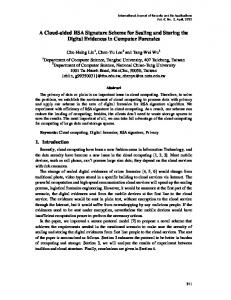
After the above-mentioned steps are executed, the authentication code of eb bits is embedded into the modified quantization levels of the compressed image block. Two possible cases of the quantization level adjustment are depicted in Figure 5. In the first case, the selected candidate bs is less than b and the adjusted quantization level b’ is still less than b. In the second case, the selected candidate bs is greater than b. By successively embedding each authentication code generated from the random value into the compressed trio of BTC, the authentication code embedded process is done.
Figure 5. Possible cases of the quantization level adjustment An example of the authentication data embedding process is described in the following. Suppose eb is set to 3. In this example, the MPBTC compressed trio (75, 152, (1000110011101111)2) of the 4×4 image block as shown in Figure 1 is used to embed the first authentication code of 3 bits as shown in Figure 4(d). In other words, the authentication code (000)2 is embedded into the difference value 77 that is generated by subtracting 152 by 75. The 3-bit parity value 5 of the difference value is then computed by using Eq. (7). Since the authentication code (000)2 is different from the parity value, we need to find out the best candidate to replace the quantization level 152. According to Eq. (8), the first candidate 147 is generated where 147 equals The second (75 77 / 8 8 0). candidate 155 is then computed by using the second rule in Eq. (9) because the first candidate 147 is less than the
17
International Journal of Security and Its Applications Vol. 7, No. 3, May, 2013
quantization level 152. Finally, the second candidate 155 is chosen to replace the quantization level 152 because it is much closer to 152 than 147. In the second step, the quantization levels 75 and 155 are to be adjusted. It is computed that the absolute difference between these two quantization levels equals 80. According to Eq. (11), the displacement value 1 is generated where finally, 1 80 77 / 2. the adjusted quantization levels 76 and 156 are generated by using Eqs. (12) and (13), respectively. The above described example belongs to the second case depicted in Figure 5(b) because the selected candidate 155 in the first step is greater than the quantization level 152. 3.3. The tamper detection procedure The goal of the tamper detection procedure is to detect whether the compressed image of BTC is modified or not. Some system parameters, such as W, H, eb, and the random number seed, should be set in the tamper detection procedure. In addition, the BTC compressed codes of the image are required. The compressed image consists of wh trios of (a, b, BM) where w and h equal W/n and H/n, respectively.
Figure 6. Flowchart of the block-based tamper detection procedure The flowchart of the tamper detection procedure is shown in Figure 6. To determine whether these wh image blocks are tampered or not, two sets of authentication codes are to be generated. The first set of authentication codes is generated by the random values induced by the selected random number seed. A total of wh random values are generated. Each random value rv is then converted into eb-bit authentication code ac by using Eq. (5). By sequentially generating the eb-bit authentication code for each random value, a total of wh authentication codes are produced. The second set of the authentication codes is generated from the received quantization levels of each compressed block. The difference value dv between the two quantization levels
18
International Journal of Security and Its Applications Vol. 7, No. 3, May, 2013
a and b is first computed by using Eq. (6). Then, the extracted authentication code eac is computed by performing modulus function on dv where eac equals dv mod 2eb. In other words, eac records the eb-bit parity value of the difference value dv. By sequentially generating the eb-bit extracted authentication code from the quantization levels of each compressed trio, a total of wh extracted authentication codes are generated. When two sets of authentication codes are available, we can determine whether each image block x is tampered or not. If the extracted authentication code eac equals the authentication code ac, x is classified as a clear block. Otherwise, x is classified as a modified block. In the detected image, a white pixel and a black one are used to represent a clear block and a modified block, respectively. When the authentication code ac and the extracted authentication code eac for each image block x are sequentially checked by the same process, the roughly detected image RDI is now available. A tamper refinement process is then performed on the roughly detected image RDI because the extracted authentication codes that were generated by using the the modulus operation in the tampered areas may still be the same as the authentication codes generated by using the random values. In other words, it may happen that the modified difference value between the quantization levels has the same eb-bits remainder as the authentication code generated by the random value in the embedded image. The probability of the above mentioned situation approximately equals 1 / 2 eb . For example, about 50% and 25% false detection will be found when 1-bit and 2-bit authentication codes are used in the proposed scheme, respectively. The probability of this situation decreases as the value of eb increases.
p
p
p
p
(a) Case 1
(b) Case 2
(c) Case 3
(d) Case 4
Figure 7. Four test cases for tamper refinement To improve the detecting accuracy, an iterative tamper refinement mechanism is employed to refine the roughly detected image of size w h. In each round, we need to check whether each white pixel will be changed to a black one or not. Four test cases as shown in Figure 7 are sequentially checked to decide whether each white pixel will be changed to a black one or not. In Figure 7, p denotes the selected white pixel to be processed. In the first case in Figure 7(a), if the adjacent up and down pixels of p are black, p is changed to a black pixel. In the second case in Figure 7(b), if the adjacent left and right pixels of p are black, p is changed to a black one. Similarly, two additional cases for the 45 and 135 splay black pixels of p are listed in Figures 7(c) and 7(d), respectively. After examining each white pixel to determine whether it should be changed to a black one or not, the total number of modified pixels in each round is computed. If the number of modified pixels is greater than or equal to 1, the same tamper refinement process is iterated. Otherwise, the tamper refining process is stopped. The above-mentioned tamper refinement process does not guarantee to remove the white pixels within the tampered object. To solve the problem, an additional process to remove the small-sized connected components of white pixels within the tampered areas can be used.
19
International Journal of Security and Its Applications Vol. 7, No. 3, May, 2013
(a) Airplane
(b) Boat
(c) Girl
(d) Goldhill
(e) Lenna
(f) Pepper
(g) Sailboat
(h) Toys
Figure 8. Eight grayscale testing images
20
International Journal of Security and Its Applications Vol. 7, No. 3, May, 2013
4. Experimental Results Our experiments are performed on windows 7 PC with an Intel Core™ i5 2.80GHz CPU and the 2GB RAM. The testing programs are implemented by using Bloodshed Dev C++ Version 4.9.9.2. In the simulation, the AMBTC scheme instead of the MPBTC scheme is employed because the AMBTC scheme is proved to be the MSE optimal scheme when the block mean value is used as the quantization threshold for pixel grouping. Eight grayscale images of 512×512 pixels “Airplane”, “Boat”, “Girl”, “Goldhill”, “Lenna”, “Pepper”, “Sailboat” and “Toys”, as shown in Figure 8, are used in the simulation. Experimental results of the reconstructed image qualities of the AMBTC scheme with different block sizes are listed in Table 1. It is shown that the reconstructed image quality decreases with the increase of the block size. Average image qualities of 40.597 dB, 33.232 dB, and 29.898 dB are achieved by the AMBTC scheme when the block sizes are set to 2×2, 4×4, and 8×8, respectively. The bit rates of the AMBTC scheme equal 5 bpp, 2 bpp, and 1.25 bpp when the block sizes are set to 2×2, 4×4, and 8×8, respectively. Table 1. Reconstructed image qualities of the AMBTC scheme Block size
2×2 (5 bpp)
4×4 (2 bpp)
8×8 (1.25 bpp)
Airplane
40.747
33.266
30.141
Boat
39.450
31.961
28.975
Girl
41.921
34.763
31.057
Goldhill
41.316
33.694
30.293
Lenna
40.657
33.692
30.247
Pepper
41.456
34.069
30.247
Sailboat
38.078
31.176
28.125
Toys
41.152
33.235
30.098
Average
40.597
33.232
29.898
Images
Table 2. Image qualities of the embedded images of the proposed scheme when the block size is set to 2×2 eb
eb = 1
eb = 2
eb = 3
eb = 4
eb = 5
Airplane
40.540
40.317
39.385
36.109
30.393
Boat
39.303
39.128
38.505
35.999
30.725
Girl
41.658
41.380
40.382
37.014
30.601
Goldhill
41.092
40.833
39.981
37.103
31.334
Lenna
40.461
40.247
39.442
36.432
30.652
Pepper
41.224
40.976
40.075
32.638
22.866
Sailboat
37.971
37.839
37.389
35.660
31.112
Toys
40.936
40.693
39.847
36.673
28.416
Average
40.398
40.177
39.376
35.954
29.512
Images
21
International Journal of Security and Its Applications Vol. 7, No. 3, May, 2013
Image qualities of the embedded images of the proposed scheme are listed in Tables 2 to 4 when the block sizes are set to 2×2, 4×4, and 8×8, respectively. From Table 2, average embedded image qualities of 40.398 dB, 39.376 dB, and 29.512 dB are achieved by the proposed scheme with 2×2 blocks when the eb values are set to 1, 3, and 5, respectively. In other words, the image quality losses of 0.199 dB, 1.221 dB, and 11.085 dB are obtained by the proposed scheme when the eb values are set to 1, 3, and 5, respectively. The average quality loss incurred by using the proposed scheme is less than 0.420 dB when the eb values is less than or equal to 2. From Table 3, average embedded image qualities of 33.199 dB, 32.989 dB, and 28.554 dB are achieved by the proposed scheme with 4×4 blocks when the eb values are set to 1, 3, and 5, respectively. In other words, the image quality losses of 0.033 dB, 0.243 dB, and 4.678 dB are obtained by the proposed scheme when the eb values are set to 1, 3, and 5, respectively. The average quality loss incurred by using the proposed scheme is less than 0.243 dB when the eb values is less than or equal to 3. Table 3. Image qualities of the embedded images of the proposed scheme when the block size is set to 4×4 eb
eb = 1
eb = 2
eb = 3
eb = 4
eb = 5
Airplane
33.234
33.185
33.014
32.150
29.239
Boat
31.938
31.898
31.781
31.175
28.876
Girl
34.718
34.646
34.432
33.511
29.835
Goldhill
33.657
33.602
33.426
32.769
30.293
Lenna
33.656
33.603
33.436
32.617
29.708
Pepper
34.030
33.974
33.795
31.231
23.445
Sailboat
31.155
31.125
31.023
30.611
28.850
Toys
33.203
33.155
33.005
32.214
28.183
Average
33.199
33.149
32.989
32.035
28.554
Images
Table 4. Image qualities of the embedded images of the proposed scheme when the block size is set to 8×8 eb
eb = 1
eb = 2
eb = 3
eb = 4
eb = 5
Airplane
30.125
30.099
30.018
29.613
27.955
Boat
28.963
28.943
28.879
28.574
27.319
Girl
31.038
31.003
30.900
30.517
28.701
Goldhill
30.275
30.247
30.161
29.843
28.652
Lenna
30.231
30.205
30.127
29.786
28.242
Pepper
30.230
30.204
30.123
29.782
24.129
Sailboat
28.115
28.098
28.044
27.831
26.907
Toys
30.083
30.059
29.980
29.607
27.994
Average
29.883
29.857
29.779
29.444
27.487
Images
22
International Journal of Security and Its Applications Vol. 7, No. 3, May, 2013
From Table 4, average embedded image qualities of 29.883 dB, 29.779 dB, and 27.487 dB are achieved by the proposed scheme with 8×8 blocks when the eb values are set to 1, 3, and 5, respectively. In other words, the image quality losses of 0.015 dB, 0.119 dB, and 2.411 dB are obtained by the proposed scheme when the eb values are set to 1, 3, and 5, respectively. The average quality loss incurred by using the proposed scheme is less than 0.454 dB when the eb values is less than or equal to 4. According to the results in Tables 2 to 4, it is shown that the image quality of the embedded image decreases with the increase of the eb value. In addition, less image quality loss is incurred when a larger block size is set in the proposed scheme.
(a) eb = 1
(b) eb = 2
(c) eb = 3
(d) eb = 4
Figure 9. Embedded images “Girl” of the proposed scheme when the block size equals 4×4
(a) The tampered object
(b) The tampered object in binary form
Figure 10. The tampered object of the test
23
International Journal of Security and Its Applications Vol. 7, No. 3, May, 2013
In the tamper detection simulation, the block size used in the proposed scheme is set to 4×4. Four embedded images of the proposed scheme by using the test image “Girl” are shown in Figure 9. In these four embedded images, the eb values are set to 1 to 4, respectively. In the tamper test, a doll as shown in Figure 10(a) is added on the wall of each embedded image. The binary version of the tampered area is shown in Figure 10(b). These four tampered images when the eb values are set to 1 to 4 are shown in Figure 11. The tamper object consists of 10810 pixels. A total of 749 blocks are affected by the tamper object. The pixel difference images and the block difference images for the tamper test are listed in Figure 12. From the results, some white spots within the tampered object are found in each pixel difference image. It indicates that some modified pixels within the doll have the same intensities as the original pixels in the embedded image. The total numbers of the different pixels and the different blocks of the tamper test when the eb values are set to 1 to 4 are listed in Table 5. It is shown that 749 image blocks are tampered in these tampered images.
(a) eb = 1
(b) eb = 2
(c) eb = 3
(d) eb = 4
Figure 11. Tampered images “Lenna” of the proposed scheme when the block size equals 4×4 Table 5. Total numbers of the different pixels and the different blocks in the tamper test Factors eb eb= 1 eb = 2 eb = 3 eb = 4
24
No. of different pixels
No. of different blocks
10808 10809 10809 10810
749 749 749 749
International Journal of Security and Its Applications Vol. 7, No. 3, May, 2013
The detected results of the proposed tamper detection procedure are listed in Figure 13. The roughly detected images and the final refined images are listed. According to the roughly detected images, it is shown that the number of black spots increases when the eb value increases. No white spots are found within the modified object in these final refined images. Compared to the tampered object as shown in Figure 10, the tampered area of each refined image is clearly detected. However, some modified blocks in the boundary of the tampered area cannot be detected by using the proposed tamper detection procedure.
(a) Pixel difference image (eb=1)
(b) Block difference image (eb=1)
(c) Pixel difference image (eb=2)
(d) Block difference image (eb=2)
(e) Pixel difference image (eb=3)
(f) Block difference image (eb=3)
25
International Journal of Security and Its Applications Vol. 7, No. 3, May, 2013
(g) Pixel difference image (eb=4)
(h) Block difference image (eb=4)
Figure 12. The difference images for the tamper test The total numbers of the tampered blocks in the roughly detected images and the refined images by using the proposed scheme are listed in Table 6. The numbers of the tampered blocks in the roughly detected images are equal to 378, 559, 663, and 707 when the eb values are 1, 2, 3, and 4, respectively. There are 720, 745, 753, and 756 tampered blocks in the refined images when the eb values are 1, 2, 3, and 4, respectively.
26
(a) Roughly detected image (eb=1)
(b) The finally detected image (eb=1)
(c) Roughly detected image (eb=2)
(d) The finally detected image (eb=2)
International Journal of Security and Its Applications Vol. 7, No. 3, May, 2013
(e) Roughly detected image (eb=3)
(f) The finally detected image (eb=3)
(g) Roughly detected image (eb=4)
(h) The finally detected image (eb=4)
Figure 13. Detected images of the proposed scheme Results of the false detected images of the proposed tamper detection procedures are listed in Figure 14. The false detected image blocks are found in the boundary of the tampered area in each refined image. The numbers of the false detected tampered blocks in the refined images are 33, 22, 16, and 13 when the eb values are set to 1, 2, 3, and 4, respectively. Table 6. Total numbers of the tampered image blocks in the roughly detected images and the refined images Factors eb eb = 1 eb = 2 eb = 3 eb = 4
Roughly detected image
Final refined image
378 559 663 707
720 745 753 756
27
International Journal of Security and Its Applications Vol. 7, No. 3, May, 2013
(a) False detection image with 33 black spots when eb is set to 1
(b) False detection image with 22 black spots when eb is set to 2
(c) False detection image with 16 black spots when eb is set to 3
(d) False detection image with 13 black spots when eb is set to 4
Figure 14. Results of the false detection for the tamper test The analysis of the detecting accuracy for these two tamper tests is listed in Table 7. The results of true positive (TP), true negative (TN), false positive (FP), and false negative (FN) are provided for these tests. There are 16384 image blocks for each 512512 image when the block size is set to 44. Recall that 749 blocks are affected when a doll is added into the embedded images in the tamper test. According to the results, 718, 736, 743, and 746 tampered blocks are detected for the tamper test when the eb values are set to 1 to 4, respectively. In the first tamper test, 31, 13, 6, and 3 modified blocks are not correctly detected when the eb values are set to 1 to 4, respectively. According to the error images shown in Figure 14, they exist in the boundary of the tampered object. In addition, 2, 9, 10, and 10 clear blocks are mistakenly detected as modified blocks due to the tamper refinement strategy when the eb values are set to 1 to 4, respectively. They are also located in the boundary of the tampered object according to the error images in Figure 14. Table 7. Analysis of the detection precision of the temper tests (unit: block) eb Factors TP TN FP FN
28
eb = 1
eb = 2
eb = 3
eb = 4
15633 2 31 718
15626 9 13 736
16625 10 6 743
15625 10 3 746
International Journal of Security and Its Applications Vol. 7, No. 3, May, 2013
5. Discussions and Conclusions A tamper detection scheme that embeds the authentcaiton codes into the difference value between the quantizaton levels for BTC compressed images is proposed in the paper. In the propsed scheme, the authentication codes that are generated based on the random values induced by the random number seed. The size of authentication codes for each compressed image block can be determined by users to reach a compromise between the embedded image quality and the detection accuracy in the proposed scheme. The BTC compressed codes of each image block consist of two quantization levels and the bit map. The reason why we embed the authenticaiton codes into the difference values between each pair of the quantization levels is to avoid significant loss of the image quality. To provide good image quality of the embeded image, the difference values of the quantization levels instead of the bit maps are used in the proposed scheme. Experiemntal results confirm that the image embeded qualities of the proposed scheme are quite good. For example, the image quality losses of 0.033 dB and of 0.243 dB are obtained by the proposed scheme when the eb values are set to 1 and 3, respectively. According to the results, it is shown that clear tampered areas can be detected for the tampered images. To provide good image qualities of the embedded images, we suggest that the size of the authentication code should be set to 2 when 4×4 blocks are used in the propsoed scheme. To be specific, the proposed tamper detection scheme can be esaily applied to the BTC compressed technqiues.
Acknowledgements This research was supported by Providence University, Taichung, Taiwan under contract the National Science Council, Taipei, R.O.C. under contract NSC 99-2632-E-126-001-MY3 and NSC 101-2221-E-126-014.
References [1] E. J. Delp and O. R. Mitchell, “Image compression using block truncation coding”, IEEE T. Communications, vol. 27, (1979), pp. 1335-1342. [2] P. Franti, P. Nevalainen and T. Kaudoranta, “Compression of digital image by block truncation coding: a survey”, Computer Journal, vol. 37, (1994), pp. 308-332. [3] M. D. Lema and O. R. Mitchell, “Absolute moment block truncation coding and its application to color image”, IEEE T. Communications, vol. 32, (1984), pp. 1148-1157. [4] Y. C. Hu, “Low-complexity and low-bit-rate image compression scheme based on AMBTC”, Optical Engineering, vol. 42, (2003), pp. 1964-1975. [5] Y. C. Hu, B. H. Su and P. Y. Tsai, “Coluor image coding scheme using absolute moment block truncation coding and block prediction technique”, Imaging Science Journal, vol. 56, (2008), pp. 254-270. [6] R. L. Riverst, A. Shamir and L. Adleman, “A method for obtaining digital signatures and public-key cryptosystems”, ACM T. communications, vol. 21, (1978), pp. 120-126. [7] F. Bartolini, A. Tefas, M. Bami and I. Pitas, “Image authentication techniques for surveillance applications”, Proceedings of IEEE, vol. 89, (2001), pp. 1403-1418. [8] D. C. Lou and J. L. Liu, “Fault resilient and compression tolerant digital signature for image authentication”, IEEE T. on Consumer Electronics, vol. 46, (2000), pp. 31-39. [9] L. Xie, G. R. Arce and R. F. Graveman, “Approximate image message authentication codes”, IEEE T. Multimedia, vol. 3, (2001), pp. 242-252. [10] P. Y. Tsai, Y. C. Hu and C. C. Chang, “A novel image authentication scheme based on quadtree segmentation”, Imaging Science Journal, vol. 53, (2005), pp. 149-162. [11] S. Ababneh, R. Ansari and A. Khokhar, “Iterative compensation schemes for multimedia content authentication”, Journal of Visual Communication and Image Representation, vol. 20, (2009), pp. 303-311.
29
International Journal of Security and Its Applications Vol. 7, No. 3, May, 2013
[12] C.Y. Lin and S. F. Chang, “A robust image authentication method distinguish JPEG compression from malicious manipulation”, IEEE Transactions on Circuits and Systems of Video Technology, vol. 11, (2001), pp. 153-168. [13] P. W. Wong and N. Memon, “Secret and public key image watermarking schemes for image authentication and ownership verification”, IEEE Transactions on Image Processing, vol. 10, (2001), pp. 1593–1601. [14] P. Y. Tsai, Y. C. Hu and C. C. Chang, “Using set partitioning in hierarchical trees to authenticate digital images”, Signal Processing: Image Communication, vol. 18, (2003), pp. 813-822. [15] T. Y. Lee and S. D. Lin, “Dual watermark for image tamper detection and recovery”, Pattern Recogn., vol. 41, (2008), pp. 3497-3506. [16] F. Ahmed and M. Y. Siyal, “A secure and robust hash-based scheme for image authentication”, Signal Processing, vol. 90, (2010), pp. 1456–1470. [17] X. Qi and X. Xin, “A quantization-based semi-fragile watermarking scheme for image content authentication”, Journal of Visual Communication and Image Representation, vol. 22, (2011), pp. 187–200. [18] J. C. Chuang and Y. C. Hu, “An adaptive image authentication scheme for vector quantization compressed image”, Journal of Visual Communication and Image Representation, vol. 22, (2011), pp. 440-449. [19] Y. C. Hu, W. L. Chen, C. C. Lo and C. M. Wu “A novel tamper detection scheme for BTC compressed images,” Opto-Electronics Review, vol. 21, (2013), pp. 137-146. [20] Y. C. Hu, C. C. Lo, W. L. Chen and C. H. Wen, “Joint image coding and image authentication based on AMBTC,” to appear in Journal of Electronic Imaging.
Authors Yu-Chen Hu received his PhD. degree in computer science and information engineering from the Department of Computer Science and Information Engineering, National Chung Cheng University, Chiayi, Taiwan in 1999. Currently, Dr. Hu is a professor in the Department of Computer Science and Information Management, Providence University, Sha-Lu, Taiwan. He is a member of ACM and IEEE. Dr. Hu Servers as the Editor-in-Chief of International Journal of Image Processing since 2009. He joints the editorial boards of several other journals. His research interests include image and signal processing, data compression, information hiding, and data engineering. Chun-Chi Lo received the B.S., M.S., and Ph.D. degrees in computer science and information engineering from the National Taiwan University, Taipei, Taiwan, R.O.C., in 1989, 1991, and 1996, respectively. In 2004, he joined the faculty of the Department of Computer Science and Information Engineering, Providence University, Taiwan. Currently, he is an Assistant Professor. His research interests include wireless sensor networks, mean-field annealing, and combinatorial optimizations.
Chang-Ming Wu received the B.S. and Ph.D. degrees, all in control and electrical engineering from the National Chiao-Tung University, Taiwan, in 1991 and 2000, respectively. From 2000 to 2007, he worked at Industrial Technology Research Institute, where he was R&D engineer for DSL and DVB-T transceiver and receiver chips. From 2007 to 2010, he was on the faculty of the Department of Computer Science and Information Engineering at the Providence University, Taiwan. Since 2010, he has been with the Department of Electronic Engineering, Chung Yuan Christian University at Taiwan, where he is
30
International Journal of Security and Its Applications Vol. 7, No. 3, May, 2013
an assistant professor. His current research interests are in the embedded system, vehicle control network, signal processing, and multivariable control system.
Wu-Lin Chen is currently an associate professor in the department of Computer Science and Information Management at Providence University. He received his M.S. and Ph.D. degrees in the School of Industrial Engineering at Purdue University in 1995, and 1999, respectively. His research interests include operations research, production management, and stochastic models.
Chia-Hsien Wen received his B.S. degree in Computer Science from Tamkang College, Taipei, Taiwan in 1976, M.S. degree in Applied Mathematics and Ph.D. degree in Computer Science from National Tsing Hua University, Hsinchu, Taiwan, in 1978 and 1994, respectively. He is currently an associate professor of the Department of Computer Science and Information Management, Providence University, Taiwan. Prior to joining Providence University in 2005, he was the director of the Computing Center at Taichung Veterans General Hospital (TCVGH). His research interests include medical image processing, medical informatics, database management, and machine learning.
31
International Journal of Security and Its Applications Vol. 7, No. 3, May, 2013
32