Youssef Hassoun, Roger Johnson, Steve Counsell. School of Computer Science and Information Systems. Birkbeck College, University of London, Malet Street, ...
Empirical Validation of a Dynamic Coupling Metric Youssef Hassoun, Roger Johnson, Steve Counsell School of Computer Science and Information Systems Birkbeck College, University of London, Malet Street, London WC1E 7HX, UK {yhassoun, rgj, steve}@dcs.bbk.ac.uk
Abstract Most object-oriented coupling measures proposed in the literature deal with coupling at the static class level. Measuring dynamic object coupling on the other hand gives us the potential for greater insight into system structure and a comparison of the architectural aspects of different systems. In previous work, we theoretically validated a Dynamic Coupling Metric (DCM) and showed, with the aid of a small example, how a system with meta-level characteristics contained less coupling than a corresponding system without these features. In this paper, we build on the theoretical foundations of our DCM and investigate, in more detail, an empirical validation of the metric. A profiler was developed to collect dynamic coupling data represented by message exchanges between objects at runtime; two system models with different architectural characteristics providing the same functionality were then considered. Empirical validation of the metric showed it to be a useful vehicle for comparing the runtime coupling characteristics of software systems. Results also showed that for examples covering various types of couplings, reflective systems separating the base level from the meta-level exhibited significantly less coupling when compared with corresponding systems with a single-level architecture.
1. Introduction There are two aspects of validating a software metric, theoretical and empirical. The theoretical validation amounts to proving analytically that the metric conforms to a set of formal criteria. Weyuker’s set of measurement principles [24], the properties of Briand et al. for testing the usefulness of coupling [7] and Fenton and Pfleeger’s representation condition of measurement [10], are all examples of criteria with which proposed metrics can be evaluated. On the other hand, validating a software metric experimentally is confined to the set of assumptions relating the measure of an internal property to an externally visible attribute. Observations made about the external property of the system during its execution can be gathered and co-related with an internal property defined by the metric. The assessment of this co-relation should support or refute the assumption made about the predictive power of the metric. Many metrics have been proposed and validated experimentally [4, 6, 12, 13] and most object-oriented coupling metrics proposed have dealt with static class coupling [8, 9, 16, 18]. More recently, research has tended to focus on runtime dynamic object metrics [3, 15, 20]. The motivation for introducing a dynamic coupling metric in this paper was as a means of assessing the reflective programming model [15]. Reflection or meta-programming as it is sometimes known refers to the capability of a system to reason about and act upon itself. A reflective system provides a representation of its own behaviour, in addition to the representation of the behaviour of the underlying system it describes. The latter is often referred to as the application domain or the real world [19]. In such systems, there is no difference between data and program; both represent one and the same entity. The object-oriented (OO) paradigm does not support reflection and well-known languages such as C++ and Java provide only limited assistance for metaprogramming. In C++ [22], no explicit representation of program structure is permitted besides the class code representing the problem domain. The C++ Run-Time Type Information (RTTI)
could only be considered a weak reflective mechanism which allows programs to detect the type of their objects at runtime. RTTI provides support for a type-safe down-cast and facilitates the implementation of virtual functions where knowledge of object types is required. The Java language provides limited support for reflection through its java.lang.reflect package [17]. Smalltalk [11] and CLOS [5], on the other hand, both provide reflective features allowing a program to observe, reason about and modify its own execution state or alter its meaning. One important aspect of reflection is the ability to manipulate a program’s execution state at runtime. The behaviour and the structure of a reflective system changes during program execution. Here, program execution can be thought of as an ordered sequence of program steps in time and the program state at one step in the sequence is the sum over the states of all objects present at this point of time. A change of behaviour or structure (or both) reflects a change of coupling between objects. In this paper, we build on the theoretical foundations of a Dynamic Coupling Metric (DCM) proposed in earlier work [15] and investigate in more detail the empirical validation of the metric by applying it to a reflective system. We provide a framework showing how to compare the object coupling behaviour of different systems. Our hypothesis is that reflective systems based on the separation of base level and meta-level objects show less runtime coupling when compared to equivalent static systems exhibiting the same behaviour. This hypothesis is based on the observation that in reflective systems, objects can interact (exchange messages) without their respective classes being directly related at the class level. In addition to inheritance, polymorphism and introspective Application Programming Interface (API), a reflective system is supported by runtime mechanisms such as behavioural and/or structural reflection that allow the program to manipulate its own execution state. This allows for a flexible object communication and less object coupling as a result. The next section describes related work. In Section 3, a definition of the DCM metric is given. Section 4 outlines the different types of an object’s coupling and Section 5 deals with the techniques used for automating data collection process. In Section 6, two different sample systems are considered for which DCM data is collected and analysed and finally, in Section 7 we draw conclusions and discuss future work.
2. Related work In [15], the theoretical validation of the DCM was described. The time dependency of the metric was used to define an ordinal scale between different types of object coupling. We identified two distinct types of couplings; firstly, static or strong coupling which persists during the whole lifetime of the objects involved, and, secondly, weak or transient coupling which ceases to exist once the task required has been fulfilled or terminates. In general, an object may need other objects to pursue the task set by a client. Arisholm et al. [3] defined a set of dynamic coupling measures and observed that regardless of the structural attribute used to define a coupling metric, predictions of external attributes based on a static analysis of the design or code became imprecise when inheritance and polymorphism were used intensively in systems. To collect dynamic coupling data, the authors used a tool in which the Java Virtual Machine (JVM) loaded a library of routines called whenever specified internal events occurred. The tool remained separate from the program under study (the sample) and interacted with it through the JVM at runtime. Our approach is similar; we do not instrument the source code to collect coupling data at runtime. Our approach is different, however, in that it does not interfere in the JVM processing at runtime; events’ specification and the merging of source code with the program for data collection are realized at compile time. In our approach, knowledge of the sample program is therefore necessary.
Mitchell and Power have also defined a number runtime metrics for coupling and cohesion [20]. The authors used the Java Platform Debug Architecture (JPDA), available as part of the Sun Microsystems Java 2 Standard Edition to obtain a runtime profile of the Java program under consideration [17]. Their approach was restricted to Java and required extra tools for sample programs written in other languages. Our approach uses Aspect-Oriented Programming (AOP) techniques [1, 2] for developing a profiler (see Section 5- Profiler Implementation). AOP tools for implementing our approach in other languages do exist. In addition to AspectJ, there are aspect language extensions for C++ and Smalltalk-80 and prototypes for C and C# are also available.
3. Definition of the Dynamic Coupling Metric The DCM is an object coupling metric and is derived from the intuitive observation that coupling between two objects can be defined in terms of the time during which one object influences the other. According to the ontological model of Wand and Weber [23], two objects are coupled if either one of them can influence the history of the other. The history of an object is defined as the sequence of its states in time. In [15], the Dynamic Coupling Measure of an object (P) during a time period ∆t, denoted by DCM(P)∆t, is defined as the sum over all program execution steps and the sum over the total number of objects, (Oi), coupled to (P): DCM(P)∆t = ΣjΣi fi(tj)Xgp (|Oi|) ……………..…. (I) where: i=0,1,2,... number of coupled objects, Σi is the sum over the set of objects coupled to P, ∆t is an ordered sequence of program execution steps and Σj is the sum over the program execution steps; fi(tj) assumes values 1 or 0 depending on whether coupling of the ith object is active at tj or not, X denotes normal multiplication and gp(|Oi|) denotes the complexity measure of the ith object coupled to (P). Time units are defined as the individual program steps during program execution. When an object P is created at some time t (i.e., at some step during program execution)1, the default value of µ(P) is determined by the (static) class structure. In the ontological model of [23], a system is a set of things (objects) in which every object is coupled to at least one other object in the set. At the system level, the coupling measure in a time interval ∆t is the sum of all measures defined in formula (I) over all the objects of the system, i.e., DCM(system)∆t = Σk(over all system objects) µ(k) ……………..…. (II) The form of gp(|Oi|) depends, as observed by Briand et al. [7], on the goal of the measurement. The goal is determined partly by the external attribute or quality we associate with our measure. DCM is concerned with the internal attribute of object coupling.
4. Object Coupling Types Object interactions are determined by their class relationships. In this section, we discuss the connection between object coupling types (static and transient) and the underlying class relationships. Class relationships imply dependencies between corresponding objects’ instances created at runtime. Independent of the class relationship inducing the coupling, the dependency between objects ceases when the dependent object is destroyed; this can occur either explicitly by invoking an object’s destructor, as in C++, or implicitly by invoking a garbage collector, as in Java and Smalltalk.
1
t=0 corresponds to the start of program execution.
Class aggregation (has-a) and class inheritance (is-a) are two examples of class relationships that induce static coupling between objects. In the case of class aggregation, the relationship of inner classes2 to their containers is ruled out, because it is purely a containment relationship at the class level. For our purposes, class aggregation that implies object composition (has-a relationship at the instance level) is relevant. Classes are defined independently of each other and the container class holds other classes (aggregates) as attributes. As far as our object coupling type classification is concerned, inheritance resembles class aggregation; inheritance induces static coupling between a child object and its parent. In addition to inheritance and aggregation there are class relationships in which classes use other classes (uses-a) to implement their functionality. For example, a class A uses a class B as a method parameter or as a return type. Alternatively, B is needed to implement the logic of a method and is used as a local variable in a method of A. An instance of the class A does not include instances of B as part of its state. This is the main difference between the (uses-a) relationship and the other two class relationships. The instances of used classes do not constitute a part of the state of the instance that uses them. The uses-a class relationship thus induces transient coupling at the object level. The coupling relationship between application objects and meta-objects of a reflective system is transient. In strongly typed object-oriented languages, sub-type polymorphism may be used to implement meta-object classes in a generic manner, thus eliminating explicit compile-time class dependencies. This makes the coupling between objects at the base level and those at the metalevel a purely runtime issue. In reflective systems, base objects are bound to meta-objects at runtime and decoupled from them after the changes made at the meta-level are reflected back to the base level. In this study, we consider two types of objects’ coupling identified by our DCM, namely, static or strong coupling and weak or transient coupling.
5. Profiler implementation One way to collect coupling data of interacting objects is to intercept the message exchanges between them. In C++ and Java, message exchange is realized as method invocation on objects. In these languages, programming constructs (loops, conditional statements, assignments, etc.) are used to control interaction between objects but themselves take no part in it. For C++ and Java systems, the program execution steps relevant to coupling are object instantiations and method invocations. In Smalltalk, all execution steps must be considered since there is no concept other than object and all language constructs are messages sent to objects. A trivial implementation of the idea of intercepting objects’ message exchange is to insert intercepting code at the appropriate places (object instantiations and method invocations) in the program. Modifying existing code implies extra costs of testing and maintenance. To avoid this, we developed, using AOP techniques, the interceptive code as an independent programming unit and merged it with the target program using a weaving tool. In AOP [1, 2], intercepting code constitutes an aspect or a concern whose code crosscuts that of the system’s core concerns. For our programs in Java, we used AspectJ to implement intercepting code and then insert it at the appropriate join points, i.e., at the places where the aspect code crosscuts the program. AspectJ is an extension of Java with new language constructs such as pointcuts, advices and aspects that allow the separation of aspects from core concerns. Figure 1 provides the main features of the interceptive code implemented in AspectJ. We note that the Interceptor aspect makes no reference to application programs and is abstract (line 7). Abstract aspects cannot be merged and must be specialized (through the extends mechanism) be2
Inner classes are defined within the scope of their container classes and are allowed in C++ and Java.
fore their code can be weaved into the application code. Two abstract pointcuts with no parameters are defined corresponding to objects’ creation and methods’ invocation (lines 9-10). A third pointcut (line 11) is defined to invoke data collection advice code. Data collected throughout program execution is manipulated using this advice (lines 39). In extending the aspect, i.e., defining concrete aspects that apply in certain contexts, the join points at which the corresponding advice code is executed must be specified. Join points are specified using pointcut designators (or events) such as constructor or method calls, method body execution and the execution of code belonging to a class. The code to be executed when an object is created or when a method is invoked is implemented as an advice. Advices can be invoked before, instead of or after join points are reached. Aspect extension languages provide APIs allowing the invocation of the target method from within the around-advice (lines 22-23, 31-32 and 39). Due to space limitations in this paper, details on the implementation of the advice code are available on-line3. import import import import import
java.lang.reflect.*; org.aspectj.lang.JoinPoint; org.aspectj.lang.reflect.CodeSignature; org.aspectj.lang.Signature; java.util.*;
abstract aspect Interceptor { abstract pointcut myConstructor(); // captures object creation event abstract pointcut execsTest(); // captures object interactions abstract pointcut dataCollection(); // for collecting data
//1 //2 //3 //4 //5 //6 //7 //8 //9 //10 //11
Hashtable objects_ht=new Hashtable();//holds object as key, its DCM as value Hashtable types_ht=new Hashtable(); //holds DCM of all objects of a class Vector task_objects=new Vector(); // objects involved in a task Vector all_objects=new Vector(); // all created objects Vector all_types=new Vector(); // all class types Hashtable exec_ht=new Hashtable(); // holds execution step as key private int exec_step=0; // holds no. of execution steps after(): myConstructor() { exec_step +=1; } void around(): myConstructor() { Signature sig= thisJoinPoint.getStaticPart().getSignature(); String class_name=sig.getDeclaringType().getName(); String the_object=""+thisJoinPoint.getThis(); if (thisJoinPoint.getThis()!=null) all_objects.add(the_object); ... } after(): execsTest() { exec_step +=1; } Object around(): execsTest() { String the_object=""+thisJoinPoint.getThis(); if (thisJoinPoint.getThis()!=null) task_objects.add(the_object); Object result = proceed(); ... } void around(): dataCollection() { Enumeration okeys=objects_ht.keys(); ... }
Figure 1. Main features of the interceptive code
3
Profiler code is available at: http://www.dcs.bbk.ac.uk/~yhassoun/metricCode
//20 //21 //22 //23
//30 //31 //32
//39 //40
5. Data Collection Process To collect data for subsequent analysis, configuration files were used to store DCM values corresponding to static coupling resulting from aggregation and inheritance class relationships. Configuration files can be realized in XML or any other suitable text format. When an object is created, its DCM value is set to that specified in the configuration files. The program checks the type of the object and compares it with all the class names listed in the file. With each execution step corresponding to message exchange, the measures of all existing objects are updated by adding their corresponding DCM values. When a message exchange results in a chain of objects’ interactions, the DCM value of the leading object (initiating the series of calls) is incremented by the contributions of objects involved (and needed to fulfill the leading object’s task). We note that implicit inheritance relationships implied by the implementation language were not considered as part of our study. An execution step counter is incremented every time an object is created or exchanges messages with other objects. To apply the Interceptor aspect in a certain context, we needed to extend the aspect (i.e., make it concrete) and specify the join points. Invoking the AspectJ weaving tool inserted the corresponding advices’ code at the specified points in the application program. Figure 2 shows an exmple of a concrete aspect that allows the application of the abstract Interceptor aspect in an application named TestStaticModel and involves objects of types A, B, C and D. We assumed that the application program, before terminating, calls its method collectData() to allow for DCM data collection. Public aspect ConcreteInterceptor extends Interceptor{ pointcut myConstructor(): (within(TestStaticModel)||within(A)||within(B)|| within(C)||within(D)) && execution(new(..)); pointcut execsTest(): (within(TestStaticModel)||within(A)||within(B)|| within(C)||within(D)) && execution(* *(..)); pointcut dataCollection(): (within(TestStaticModel)) && call(void collectData(..)); }
Figure 2. Concrete aspect to intercept executions of the static system test program
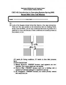
6. Empirical Validation As part of our empirical validation, we considered two Java systems with different architectural characteristics providing the same functionality. Classes in the first model, henceforth referred to as the static system, were related through the known has-a and uses-a relationships and all the objects interacted accordingly. In the second model, i.e., the meta-system, the class structure exhibits less coupling due to the dynamic nature of the coupling relationships. In the latter system, object interaction is more flexible and supported by polymorphism and reflective features of the Java programming language. Application objects are attached dynamically to reified meta-objects and decoupled from them after the reflection process is over, i.e. after changes made at the metalevel have been reflected back to the base level. In collecting data, we set the complexity measure factor of formula (I), gp(|Oi|)=1; this meant that our DCM measure associated equal and constant weight with all class couplings underlying object interactions. As a result, the structure of configuration files was simplified and could be deployed as list of pairs in the format (class name, DCM integer value). Setting the DCM complexity measure factor to a constant did not affect the end result of comparing the two systems under study. Figure 3 depicts the class diagram of the static system in UML notation [21], showing only class names and their relationships. The configuration file corresponding to the model of Figure 3 con-
tains four entries: (A, 2), (B, 1), (C, 0) and (D, 0); the format is simplified (due to setting gp(|Oi|)=1) and the configuration was realized as a Java properties file.
Figure 3. Class structure of the static system Table 1 shows the total number of objects of each of the class type in the model (columns A, B, C and D), the DCM value of each type (DCM(A), DCM(B)) as well as the overall DCM value of the system (DCM(system)) together with the total number of objects (column objects) in terms of program execution steps (pes). DCM(C) and DCM(D) remain zero throughout program execution, because they correspond to independent objects (and hence are not shown in the table). row
pes
A
DCM(A)
B
DCM(B)
C
D
objects
DCM(system)
0 1 2 3 4 5 6 7 8 9
1 10 100 200 500 1000 2000 3000 5000 10000
0 1 2 2 2 102 102 202 222 222
0 9 356 702 1902 12602 74052 166752 194892 214892
0 1 2 3 3 103 253 353 373 373
0 5 179 436 1336 6768 60636 107586 123576 138576
0 1 2 5 5 105 255 355 375 375
0 2 3 4 4 104 104 204 224 224
0 5 9 14 14 414 714 1114 1194 1194
0 14 535 1138 3238 19388 134688 274338 318468 353468
Table 1. DCM values as a function of the execution steps of a static model test program Table 1 shows an increase in the DCM values and in the total number of objects as the pes-values increase. Increase in the individual DCM values depend on object’s contribution to the interactions and is calculated according to the scheme described in Section 5. To increase objects’ interactions, new objects were created and methods invoked on them. In some cases, methods’ invocations induced further invocations on other objects, resulting in a chain of objects’ interactions. To produce the above results, different aspects of objects interactions were considered: 1) 2) 3) 4)
Object instantiation, Object instantiation through object composition, Method invocations leading to a chain of objects’ interactions and, finally, Method invocation corresponding to simple client-target object interaction (no further invocations).
These aspects cover object coupling types discussed in Section 4. We note that coupling due to isa class relationship is considered identical to coupling due to has-a relationship. The class structure of the meta-system is illustrated in Figure 4 where functions of interfaces and those of classes relevant to proxies’ mechanisms of binding and method invocations are shown. It involves, in addition to the classes of the static system, classes that allow customization of objects’ behaviour at runtime [14]. Polymorphism and Java’s dynamic proxies mechanism are used to implement the model. We arbitrarily chose to decouple B and C from A and shift them to the meta-level. The resulting system exhibits the same functionality provided by the static model.
Figure 4. Class structure of the meta-system The configuration file corresponding to the model of Figure 4 contains two new classes when compared with the static case, i.e., MO_BC and BC_Proxy. The DCM default values of A and B change and thus for this model we have the pairs: (A, 1), (B, 0), (C, 0), (D, 0), (MO_BC, 0) and (BC_Proxy, 2). Table 2 shows the DCM values and the number of objects present together with the overall DCM value of the meta-model system as they change with program execution steps. The numbers in the pes-column are slightly different from the corresponding numbers in the static case of Table 1. This is due to the difference in the set of objects involved and interactions needed to establish the connection between base objects (A and D) and meta-objects (MO_BC, BC_Proxy, B and C). The same application code is applied in both models. In the meta-case, calls on A instances are replaced by calls on a proxy object to which the A instance is bound (see Figure 5). We note that only one BO_BC object was created and used to bind the different base objects (of type A) and that only one BC_Proxy object was created and used to represent all these base objects. DCM(MO_BC)=0, DCM(B)=0, DCM(C)=0 and DCM(D)=0 over all the steps (and hence are not shown in Table 2). row
Pes
A
DCM(A)
D
0 1 2 3 4 5 6 7 8 9
1 15 105 201 501 901 2051 2951 4931 9931
0 1 2 2 2 102 252 352 372 372
0 5 180 356 956 6206 59506 105756 119806 129806
0 2 3 4 4 104 254 354 374 374
MO_BC BC-Proxy
0 1 1 1 1 1 1 1 1 1
0 1 1 1 1 1 1 1 1 1
DCM B (BC_Proxy)
0 9 180 349 949 1149 1649 2849 6689 16689
0 1 1 1 1 1 1 1 1 1
C objects
DCM (system)
0 1 1 1 1 1 1 1 1 1
0 14 360 705 1905 7355 61155 108605 126495 146495
0 7 9 10 10 210 510 710 750 750
Table 2. DCM values as a function of the execution steps of the meta-model test program // static case A a2=new A(); System.out.println("getting bi with a2: "+a2.getBi()); for (int i=0; i