Proceedings of the Workshop on Software Engineering Methods for ...
Recommend Documents
J. M. Zaha, M. Dumas, A. ter Hofstede, A. Barros, and G. Decker. Service in- teraction ..... sequence diagrams or similar models are used [9]. A Use Case is ...
creasingly contributed to mastering the inherent and ever increasing complexity of software ...... Recent debugging methods as described in [4, 8, 9, 11] help the.
Mar 22, 2015 - Software-Intensive Systems Development Case Study ... The original plan was to build a Web portal for NZ organic farmers to offer their ... You work for the 7th vendor - a systems integration company whose specialty is getting.
The RNA-SSD algorithm [2] by Andronescu et al. and RNAinverse from .... and the output structure of the RNA folding server) are then compared together ...... mented using dedicated global propagators (either for their consistency level or.
as direct memorization is out of discussion. To tackle this problem we use a ...... Some pathways, such as glycolysis, however use some of these metabolites as ...
Security, Software Engineering. 1. WORKSHOP ... Software engineers and practitioners should assimilate basic security ... WORKSHOP OUTLINE. This year the ...
Apr 13, 1999 - Practical Software Engineering Support for Component-Based Control. Systems. Francios ...... accounting packages) by many different vendors.
Kingdom. Frank Maurer, University of Calgary, Canada. Nikolay Mehandjiev, University of Manchester, United. Kingdom. Steven Reiss, Brown University, USA.
its 5th edition this workshop will investigate the application of usability ..... The UX Modeler looks like and functions like an online social network. ...... Usability Planner is an online tool [14] that has been conceived for offering advice .....
Indira Gandhi National Open University, Lucknow. Y Y Y Y. 2 ... In the fourth year course, three topics, usability, building and designing web applications,.
Jul 15, 2011 - Language Processing, Proceedings of the Conference, pages 1213â1221, Edinburgh, ..... into the main automaton, and for all prefixes which call the ...... simple and transforms a fictitious proto-language. PL into a daughter ...
Jul 15, 2011 - 1It should be noted that all foreign names in Serbian texts are transcribed, regardless of whether they are written in Latin or Cyrillic alphabet.
Jul 15, 2011 - which a certain string function Ï{e,e } maps to the. Table 1 ...... proving the performance of sequence learning mod- ...... x = a1 ...an over Σ is a finite concatenation of ...... a python program, arpa2fst.py which may be used. 66
Generating Requirements Views: A Transformation-Driven ... scenarios, requirements sentences, lexicons, component models, class diagrams, entity- ..... 10 / 14. Volume 3 (2006). Figure 4 portrays an example of scenarios ..... of the Workshop on Compo
Aug 24, 2008 - Multilingual Grammar Resources in Multilingual Application Development. Marianne ...... MedSLT translates between Arabic, Catalan, En-.
Aug 24, 2008 - A More Precise Analysis of Punctuation for Broad-Coverage Surface Realization with CCG ...... pared to the best baseline model using oracle n-.
Aug 24, 2008 - Multilingual Grammar Resources in Multilingual Application Development. Marianne ..... Context Free Grammar, Right Linear Unification Grammar ..... Our basic goal will be to make text and speech ... sity, and is freely available for do
[email protected] ... Abstractâ The development of sustainable software has been .... definition sustainable software development is defined as 'the.
into software engineering processes and methods. Using. Web 2.0 tools to assist with communication and coordi- nation is only one application of Web 2.0 tools ...
Victoria, Canada [email protected]. Margaret-Anne Storey. University of Victoria. Victoria, Canada [email protected]. Kate Ehrlich. IBM TJ Watson Research.
of metaheuristic search techniques to Software Engineering problems .... whereby the tabu move might lead to the best solution ob- tained so far. ... The talk presented a template Tabu search engine, which can .... On the optimization of the.
UB8 3PH. United Kingdom ... http://www.discbrunel.org.uk/seminal/seminalhome.html ..... sizing for analog electrical circuits using genetic program- ming.
2 platform. The number of publications submitted for the conference was smaller than expected. This ...... http://www.upnp.org/specs/arch/UPnP-DeviceArchitecture-v1.0-20060720.pdf ...... 6Web of Trust RDF Ontology: http://xmlns.com/wot/0.1/.
Proceedings of the Workshop on Software Engineering Methods for ...
oriented analysis and design methods that bridge the gap between business and ...... In Proceedings 3rd International Workshop on Web Services and Formal.
Daniel Lübke (editor)
Workshop on
Software Engineering Methods for Service-Oriented Architecture 2007 (SEMSOA 2007)
SEM SOA Proceedings
Hannover 2007
Preface Service Oriented Architecture (SOA) is a new emerging style for building business applications: The software is directly based on the business processes which are used to compose software services into an application. SOA has become a hype: Many researchers and practitioners explore this area. Whereas the ongoing SOA discussion mostly concentrates on dynamic service discovery, new business methods and the business process side, the development side is normally neglected. One important question in this regard is which (proven) software engineering methods can be applied well in SOA implementation projects. What gaps and pitfalls have been discovered in practice, which remain without feasible solutions? Since mostly all SE methods have been geared towards objectoriented software design in the last years, methods and practices have to be adapted to meet the requirements of the new architectural style. This workshop therefore aims to bring together researchers and practitioners from the SOA field in order to exchange ideas and experiences related to adopted or new software engineering methods for SOA and experiences related to them. This encompasses methods, models and techniques for the whole software life cycle. Hopefully, this will result in new ideas and cooperations in this field. For this workshop, there were 10 submissions. Each submission was reviewed by at least 3 program committee members. At the end 8 papers were accepted. Hopefully, this workshop will be successful. I like to thank all the people who worked towards that goal. Especially, I like to thank all program committee members, who invested their time in reviewing the submissions, and all the members of the Software Engineering Group at the Leibniz Universität Hannover for helping to organize this workshop.
Hannover, May 2007
Daniel Lübke
Program Committee Members • • • • • • • • • • • •
Luciano Baresi, Politecnico di Milano, IT Nico Brehm, University Oldenburg, DE Nicolas Gold, King's College London, GB Katrina Leyking, DKFI, DE Daniel Lübke, Leibniz Universität Hannover, DE Jorge Marx Gómez, University Oldenburg, DE Jan Mendling, WU Wien, A Andreas Schmietendorf, FHW Berlin, DE Kurt Schneider, Leibniz Universität Hannover, DE Branimir Wetzstein, University Stuttgart, DE Uwe Zdun, Vienna University of Technology, A Olaf Zimmermann, IBM Zurich Research Laboratory, CH
Table of Contents Multi-staged and Multi-viewpoint Service Choreography Modelling Alistair Barros, Gero Decker, Marlon Dumas...................................................1 Dealing with User Requirements and Feedback in SOA Projects Daniel Lübke, Eric Knauss...............................................................................16 Semantic Model-Driven Development of Service-centric Software Architectures Claus Pahl, Ronan Barrett ...............................................................................31 Architectural Decision Models as Micro-Methodology for Service-Oriented Analysis and Design Olaf Zimmermann, Jana Koehler, Leymann Frank..........................................46 Towards a Holistic Architecture Platform Tony Shan, Winnie Hua....................................................................................61 Service-oriented Development of Federated ERP-Systems Nico Brehm, Jorge Marx Gómez......................................................................76 Resource Metrics for Service-Oriented Infrastructures Dmytro Rud, Andreas Schmietendorf, Reiner Dumke ......................................90 Model Driven Testing of SOA-based Software Chris Lenz, Joanna Chimiak-Opoka, Ruth Breu ..............................................99
1
Multi-staged and Multi-viewpoint Service Choreography Modelling Alistair Barros1 , Gero Decker2 , Marlon Dumas3 1
Abstract. Recent approaches to service-oriented systems engineering start by capturing the interactions between services from the perspective of a global observer, leading to so-called service choreographies. The rationale is that such choreographies allow stakeholders to agree on the overall structure and behaviour of the system prior to developing new services or adapting existing ones. However, existing languages for choreography modelling, such as WS-CDL, are implementation-focused. Also, these proposals treat choreographies as monolithic models, with no support for multiple viewpoints. This paper proposes a multi-staged and multi-viewpoint approach to choreography modelling. For the initial stages, the approach promotes the partitioning of choreography models and the design of role-based views; while for subsequent stages, milestone and scenario models are used as an entry point into detailed interaction models. The paper presents analysis techniques to manage the consistency between viewpoints. The proposal is illustrated using a sales and logistics model.
1
Introduction
As implementation-level web service interoperability standards mature, the need for analysis and design methods for service-oriented systems becomes even more pressing. In early proposals for service-oriented analysis and design methods [8, 2, 22, 16], global models of service interactions, also known as conversation protocols or service choreographies, play a key role during the initial stages of analysis and design. Service choreographies capture the interactions in which a collection of services engage, from the perspective of an ideal observer who would be able to see every interaction occurring between the involved services. By providing a “birds-eye” view over interactions, service choreographies allow business and IT stakeholders to build a common understanding of the structure and behaviour of the overall system, prior to approaching implementation issues. Languages such as BPSS [20] and WS-CDL [14] have been proposed as a basis for modelling choreographies. However, these languages focus on detailed inter-
2
2
Alistair Barros, Gero Decker, Marlon Dumas
action flows and treat choreographies as monolithic development artifacts. WSCDL in particular goes down to supporting the description of choreographies in a quasi-executable form, using programming constructs such as sequence, blockstructured conditional and loop structures, and variable assignment. While these languages partly support an implementation-independent approach to serviceoriented system design, it is questionable that they are suitable for the early phases of the development lifecycle, where the incremental acquisition of a common understanding by multiple stakeholders with different concerns and backgrounds is crucial. It is unlikely that business stakeholders and system analysts operating at a high level of abstraction will benefit from manipulating choreography models that include executable data manipulation steps. Instead, they are likely to be interested in viewing choreographies without the interaction flow details (e.g. role-based viewpoints), or to view milestones and specific scenarios. Only at later stages does the refinement of choreography models into executable code becomes a concern. Thus, languages and methods for choreography modelling should be compatible with multi-staged and multi-viewpoint design. By supporting multiple modelling viewpoints, it is possible to break down a service design into smaller more manageable parts that are handled by different stakeholders. In this setting, the proposition of this paper is an approach to choreography modelling based on viewpoints layered on top of a choreography modelling language, namely Let’s Dance [21]. Let’s Dance has a formal semantics defined in terms of π-calculus [6] and has been shown to be expressive enough to capture common service interaction patterns [3] and to serve as a basis for generating local views on service interactions for subsequent refinement into executable models [21]. In this paper, we define role-based, milestone-based, and scenario-based viewpoints into service choreographies, and propose techniques for managing the consistency between these viewpoints and the interaction-based viewpoints natively supported by Let’s Dance. The outcome is a set of notational elements and consistency checking techniques that provide a basis for defining serviceoriented analysis and design methods that bridge the gap between business and IT concerns. The notational elements have been used to capture a refined version of a logistics collaboration model proposed by the Voluntary Inter-industry Commerce Solutions Association (VICS).4 Meanwhile, the consistency checking algorithms have been validated through implementation and testing. After an informal introduction to the proposal using the VICS global logistics model (Section 2), the paper defines an abstract syntax for each of the proposed modelling viewpoints (Section 3). Next, the techniques for inter-viewpoint consistency verification are presented in Section 4. Finally, related work is discussed in Section 5 while Section 6 concludes.
4
See www.vics.org
3
Multi-staged and Multi-viewpoint Service Choreography Modelling
2
3
Multi-view choreography design by example
This section provides the practical setting through which the proposed choreography modelling viewpoints and extensions to the Let’s Dance language are motivated and developed. Insights are drawn from a case study inspired by the Sales and Logistics component of the VICS EDI Architecture Guide. The case study is related to the supply chain between retailers and manufacturers, covering processes where products are ordered through cyclic stock replenishment agreements over a time-horizon (e.g. 12 months), shipped and paid for. Along the way, shipments need to be managed and optimised through different types of carriers (land, rail, air, ocean), consolidated at intermediaries, crossed through the “red tape” of customs and quarantine, and delivered to consignment nodes where they are dispatched to retail stores. As a result of delivery, fulfilment of an order needs to be assessed with respect to quantity, timeliness and damage to ensure quick turn-around for payment and reimbursement. To close the loop, supply and consumer patterns are dynamically fed back into the next cycles of merchandising and collaborative forecasting, planning and replenishment. Domains and roles. End-to-end modelling of interactions of value-chains as vast as Sales and Logistics require a careful scoping of processes being analysed. To facilitate such scoping and provide a focus on models (e.g. interaction models) developed for common business objectives, we propose the notion of collaboration domains. These domains group a set of logically related models. The set of collaboration domains for the Sales & Logistics case study is depicted in Figure 1. As apparent from the figure, the collaboration domains (ellipses) scope different areas of business interest. For example, a distinction is made between Collaborative Forecasting Product Replenishment (out of which an order is produced), Logistics (governing shipment of goods), Payments, Exceptions, Order Release and Product Merchandising. Given the size and complexity of domains, we propose that they should be arranged in a hierarchical structure. For example, in Figure 1, we can see that the logistics domain is decomposed into four sub-domains: Tendering, Carrier Appointment, Delivery, and Claims & Returns. To go from collaboration domains into individual processes with detailed interactions, we propose an intermediate viewpoint: the role-based choreography view. A role-based choreography is defined for each leaf-level domain (since nonleaf domains are purely used for the purpose of abstraction). This viewpoint is illustrated for the Delivery domain in Figure 1. This viewpoint shows collaborating roles (boxes) and their interaction dependencies, expressed through channels. A channel captures the fact that there is at least one direct interaction between two or more roles and the purpose of this/these interactions. Channels are represented by small circles on lines. Cardinality constraints on channels are used to express how many participants of one role can interact with one participant of the other role. As illustrated, a Shipper interacts with a number of Carriers for Carrier Planning, while a Carrier interacts with one Shipper. A Shipper, a Consignee and a Consolidator all interact for the purpose of agreeing on a Detailed Shipment Schedule.
4
4
Alistair Barros, Gero Decker, Marlon Dumas
Product Merchandising Order Release
Delivery Negotiation
1
Collaborative Forecasting Product Replenishment
Retailer
Delivery / Dispatch Plan 1
Exceptions
1
Consignee
1
*
Distribution Center
1
Dispatch
Store
Manufacturer
Shipment Schedule 1
1
1
Payments Logistics Claims & Returns
Tendering
1
Delivery Carrier Appointment
1 1
Delivery Monitoring
Consolidator 1
1
*
Customs / Quarantine
Carrier
1 *
1
Detailed Shipment Schedule
Land Carrier
Rail Carrier
Carrier Planning
Clearance Prenotification
Ocean Carrier
Air Carrier
Coverage Notification
Clearance Monitoring 1
Delivery Planning
Detailed Shipment Schedule
1
1
*
Breakdown Service
Truck Breakdown Provision *
1 *
Shipper 1 Special Cover
* 1
1
*
1
Insurance
1 Traffic Optimization Guidance
Arrival/Pickup Conf.
*
Locative Service
Fig. 1. High-level role-based view for Delivery domain of Logistics
Multiplicity of roles can be explicitly shown, as with Shipper and Carrier for instance. This indicates that several participants of role Carrier (overlaid boxes) are involved in one choreography instance as opposed to only one participant of role Shipper taking part (single box). Another notational element, used in the representations for the Carrier and the Consignee roles, is that of role hierarchies (roles within roles). Role hierarchies can be used to express different relationships, and the exact relationship being represented needs to be specified by the modeller. In the case of the Consignee, the hierarchies mean that at least one of the sub-roles is involved in the interaction expressed against the super-role, i.e. a part-of relationship. Consignee also illustrates that further interaction dependencies can be expressed between sub-roles. Alternatively, the relationship between super- and sub-roles could reflect specialisation, where all sub-roles carry the same interaction dependencies as the super-role, and each may carry additional dependencies. This applies to the Carrier and its sub-roles. With interaction dependencies between roles, through channels, in place, individual message exchanges can be captured. We propose that channels are assigned a set of message interactions in terms of message type and direction of flow. By this assignment to channels, the message interactions between collaborating roles is captured, although they remain unordered. Milestones, scenarios and interactions. The models described so far are static: they do not describe control flow relationships between interactions. Below, we introduce viewpoints where interactions and their relationships are captured in more detail. Since the number of participants and interactions can be very large, these detailed viewpoints can be difficult to build and comprehend. Thus, a mechanism is needed to partition these models. This is achieved through the notion of milestones depicted in Figure 2. Milestones (diamonds) represent the main global states choreography instances can be in and as such are used as “sign-posts”. In complex choreogra-
5
Multi-staged and Multi-viewpoint Service Choreography Modelling Collaborative Forecasting Product Replenishment Operational Delivery Contract Established
Carrier Appointment
Delivery
Delivery Event Planning
Shipment Schedule Prepared
Carriers Selected
Variations from Delivery Contract Finalised
Ad-hoc Requests Finalised
Final Shipment Schedule Issued
Customs/ Quarantine Pre-Clearance Processing
Payments
Variations Prepared
Shipment Schedule Finalised
Consolid. Pick-up/ Delivery Confirmation
5
Carrier Variations Processing
Carrier Variations Identified
Varied Carriage Issued
Carrier Pick-up/ Delivery Confirmation
Exceptions
Shipment Commenced
Claims & Returns
Fig. 2. Milestones related to Delivery domain
phies, milestones are useful since the details of processes which lead to milestones being reached can be omitted. To illustrate the point, Figure 2 depicts milestones primarily concerning Delivery, with some links to related milestones in processes of other domains shown. In this example, some milestones are related through Precedes relationships (arrowed lines). Some milestones might never be reached for a particular instance of a choreography. For example and as explained in details later, if a guard attached to an interaction evaluates to false, the interaction is skipped, and so are all other interactions that directly or transitively follow it according to the Precedes relation. Also, some milestones may be skipped as a result of Inhibits relationships. An Inhibits relationship (line crossed by a bar) expresses that if a milestone is reached, the target milestone can no longer be reached for the current instance of the choreography (i.e. it will be skipped). In the example, a Shipment Schedule Prepared milestone being reached will result in either a Shipment Schedule Finalised (SSF) or Carrier Variations Identified (CVI) milestone being eventually reached, but not both since these milestones “inhibit” each other. If we want to express that a milestone can still be reached even if a “preceding” milestone has been skipped, we should use a Weak Precedes relationship (arrowed dashed line) instead of a Precedes ones. Following the same example, Final Shipment Schedule (FSS) is “weak preceded” by the both the SSF and CVI milestones, and thus the FSS milestone will be reachable after one
6
6
Alistair Barros, Gero Decker, Marlon Dumas
of these two milestones has been reached and the other has been skipped. This example corresponds to a more general pattern where a Weak Precedes relationship is used to join two mutually exclusive paths. Another example of a Weak Precedes is given by the Delivery Event Processing milestone (e.g. next week’s delivery) which is reached after the Operational Delivery Contract Established milestone is reached, whether or not the milestones Variations from Delivery Contract Finalised and Ad-Hoc Requests Finalised have been reached. The last extension is to introduce scenarios, or specific “threads” of interactions, and to merge these scenarios to obtain detailed interaction-based choreography models (also called interaction models for short). The modelling of interactions is the central theme of choreography languages, however support for capturing scenarios (a well-established feature of analysis and design) is left open. With milestones in place, under our approach, scenarios identify interactions which serve to progress the milestones. Figure 3 illustrates how scenarios relate to milestones drawn from Figure 2, starting with a scenario yielding a milestone that is used as input for a second scenario. In the third scenario detailed in the example, the Retailer and Manufacturer negotiate required stock, and finally the Manufacturer releases order quantities. The Manufacturer then determines through the Shipper whether the allocated Carriers have capacity or not for the shipment, and accordingly two exclusive milestones result from the scenario. How large or small a scenario is, should reflect user requirements. In addition, scenarios might be split into sub-scenarios in order to allow for different variants of parts of a scenario. Shipment Schedule Prepared
Retailer
Manufacturer
Store/inventory report
Manufacturer
Manufacturer
Investigate Replenishment for Delivery Event
Retailer
Retailer
Manufacturer
Replenishment acknowledgement
Final delivery replenishment
Retailer
Carrier capacity sufficient
Shipment Schedule Finalised
Manufacturer
Retailer
Carrier capacity insufficient
Carrier Variations Identified
Fig. 3. Scenario for replenishment
Design method. The above considerations are summarised as a choreography design method in Figure 4. The rounded rectangles in this figure depict the activities of the choreography design method. The arrows describe which other activities are influenced by the outcome of an activity. First, domains need to be identified and decomposed into sub-domains. Next comes the identification of participants in the different domains. This identification mostly takes place early in the process but participants can also be included in later stages. With participants in place, role-based choreography models can be obtained by defining interaction dependencies between them.
7
Multi-staged and Multi-viewpoint Service Choreography Modelling
Milestone models provide a high-level view of the behavioural aspect of choreography models, describing the main global states choreography instances can be in. Scenarios describe which interactions are needed to get from one milestone to another and thus only focus on one part of a choreography. During scenario modelling the designers might realise that they have to introduce more participants than they have considered so far. Furthermore, re-discussing the scope of a domain might be needed when scenario modelling goes down to the level of message exchanges. It might not be obvious to what domain a certain interaction belongs to, and this may affect the grouping of scenario models and interaction models into domains. For example, does a scenario triggered by an interaction “Pickup Appointment Change Request” belong to the domain “Carrier Appointment” or to “Delivery”? Message exchanges between the different participants are identified in this activity. First, only high-level descriptions are given. Later, message structures and contents are specified in detail. The domain-relevant parts of the scenarios are aggregated into an integrated interaction model for the domain. Therefore, all participants, milestones, interactions and relationships between them are captured in this integrated choreography. Subsequently, the individual participants’ views on the choreography model are generated and distributed to the participants who now proceed to design and implement their parts of the choreography. In our previous work [21], we have proposed algorithms for generating such local participants’ views in the context of the Let’s Dance language. Finally, existing implementations might be checked to determine if they already comply with the choreography model or if changes have to be made.
3
Choreography modelling viewpoints
The top-level viewpoint of the proposed choreography design method is the domain model. A domain model is composed of a set of domains arranged in a hierarchical relation. Leaf-level domains are mapped to different models corresponding to the proposed viewpoints on a choreography. Specifically, each leaf domain maps to: (i) a role-based model, (ii) a milestone model, (iii) a set of interaction models corresponding to scenarios, and (iv) an integrated interaction
8
8
Alistair Barros, Gero Decker, Marlon Dumas
model. In this section, we present an abstract syntax for each of these types of models. 3.1
Role-based choreography models
The previous section has already motivated role-based models and has introduced the intended meaning of the different elements of such models. Figure 5 summarises the corresponding graphical representations: Rectangles represent roles. Concrete participants are bound at design-time or at run-time. Small
A
1
*
B Role2
m1
C 1
D
E
F
1
G
Fig. 5. Diagram elements for role-based models
circles represent channels while message links are depicted as dashed arrows. Message links are directed channels with a particular message type assigned. Cardinality of channels is represented by either “1” or “*” attached to the endpoint of a channel. Multiplicity of roles is represented by a double rectangle like for role B. Hierarchy is represented by containment in the diagram. We define a role-based choreography model CR to be a tuple (R, RM , C, Senders, Receivers, Card, M sg, CM , P arent) where: – – – –
– – – – –
3.2
R is the set of all roles, RM : R → {one, many} is a function assigning a multiplicity to a role, C is the set of all channels, Senders, Receivers : C → ℘(R) assign the set of roles to a channel who can send / receive messages over the channel, if the sets of senders and receivers are disjunct, the channel is a message link (M L := {ml ∈ C | Senders(c) ∩ Receivers(c) = ∅}), Card : {(c, r) ∈ C × R | r ∈ Senders(c) ∪ Receivers(c)} → {one, many} is a function assigning a cardinality to role r for channel c, M sg is the set of all message types, CM : M L → M sg is a partial function linking message links to message types, P arent ⊆ R × R specifies the hierarchical relationships between a role and its sub-roles (P arent must be acyclic) and the cardinality “many” is only used in the presence of the multiplicity “many” of the corresponding role: ∀(c, r) ∈ Card [c = many ⇒ RM (r) = many]. Milestone, scenario and interaction models
In previous work [21] we have presented Let’s Dance as a language for modelling service interactions and their dependencies. Below, we enrich the language with
9
Multi-staged and Multi-viewpoint Service Choreography Modelling
9
milestones. That way models like they were motivated in section 2 are specified. Figure 6 contains the graphical elements for representing milestone and interaction models. Milestones are represented by diamond shapes and interactions
m1 {A, B}
A
m2 {all}
B
B
m5
m6
If condition X fulfilled (B)
A
B
message msg5
C
message msg2
A
m4
message msg3
message msg1
B
m3
repeat until x msg sent (B)
B message msg4
C
B
C
message msg6
Fig. 6. Diagram elements for milestone and interaction diagrams
using rectangles. These roles indicated in brackets describe which participant has to be notified as soon as the milestone is reached. If all participating roles are to be synchronised “all” appears in brackets or the brackets are omitted. The P recedes relationship between two elements (milestones or interactions) e1 and e2 indicates that e1 must have been executed / reached before e2 can be executed / reached. A W eakP recedes relationship between e1 and e2 indicates that e2 can only be executed / reached after e1 has been either executed / reached or after it has been skipped. An Inhibits relationships between e1 and e2 indicates that e2 cannot be executed / reached after e1 has been executed / reached (i.e. e2 is then skipped). Two-directional Inhibits relationships are represented like in the case of m3 and m4. Interactions can either be elementary or composite. In the case of elementary interactions a participant of a certain role sends a message of a given type to another participant. In Figure 6 a participant of role A sends a message of type m1 to a participant of role B. Composite interactions allow for grouping of one or more interactions. Interactions can be guarded, i.e. they may only occur if a guard condition evaluates to true, or they can be repeated. It is specified which participant evaluates the guard condition and the repetition expression. Below, we introduce three types of models corresponding to different viewpoints into a choreography: milestone, scenario and interaction models. Milestone models are composed only of milestones and relationships between them. Meanwhile, scenario models are composed of milestones, interactions and relationships between them. The purpose of a scenario model is to show how to go from a set of milestones to another. Scenario models are not limited to one domain and may be used to show dependencies between milestones and interactions from different domains. Scenario models can be nested, i.e. different sub-scenario models
10
10
Alistair Barros, Gero Decker, Marlon Dumas
may refine a given scenario model, showing specific variants. A similar notion can be found in Message Sequence Charts [18] which capture specific paths of interactions between a number of parties. But in contrast to traditional MSCs, we allow scenario or sub-scenario model to show alternative paths (i.e. we allow conditional branching in scenario models)5 . Finally, interaction models show all milestones and interactions from one domain as well as their relationships. We introduce a unified abstract syntax for milestone, scenario and interaction models by defining interaction models as the most general viewpoint, and the other two as special cases. An interaction model CI is a tuple (I, M , RI, RT , GI, R, RM , c0 , P recedes, W eakP recedes, Inhibits, P arent, Sends, Receives, MR, Msg, IM ) where – – – – – – – – – –
– – – –
I is the set of milestones and interactions, M ⊆ I is the set of milestones, RI ⊆ I \ M is the set of repeated interactions, RT : RI → {w, r, f s, f c} links a repeated interaction to a repetition type (either while, repeat, for each (sequential) or for each (concurrent)), GI ⊆ I \ M is the set of guarded interactions, R is the set of roles, the function RM : R → {many, one} specifies whether many or just one participant of a role is involved in the choreography, c0 ∈ I \ M is the top-level interaction of the choreography, P recedes, W eakP recedes, Inhibits ⊆ I × I are binary relations over I, P arent ⊆ (I \ M ) × I is the relation between interactions and their direct sub-interactions and milestones, defining the set of elementary interactions EI := {i ∈ (I \ M ) | i ∈ / range(P arent)} the partial functions Sends, Receives : EI → R link elementary interactions to sending and receiving roles, MR : M → ℘(R) links milestones to sets of roles that are to be synchronised, Msg is the set of all message types and IM : EI → M sg links elementary interactions to message types.
A milestone model CM is an interaction model where I = M ∪ {c0 }. Meanwhile, a scenario model is an interaction model where no milestone is both the source and the target of P recedes and/or W eakP recedes relationships, that is: ∀m ∈ M [¬∃i, j ∈ I ((i P recedes m ∨ i W eakP recedes m) ∧ (m P recedes j ∨ m W eakP recedes j))]
4
Consistency analysis
Consistency checking is an essential aspect in multi-viewpoint approaches [8]. In this section we introduce consistency rules between role-based choreography models and interaction models as well as between milestone models and interaction models based on the abstract syntaxes given in the previous sections. 5
While this feature is not supported in traditional MSCs, it is supported in various extensions to MSCs such as Live Sequence Charts (LSCs) [10].
11
Multi-staged and Multi-viewpoint Service Choreography Modelling
4.1
11
Role-based choreography models vs. interaction models
Consistency between a role-based choreography model CR = (RR , RMR , CR , SendersR , ReceiversR , CardR , M sgR , CMR , P arentR ) and an interaction model CI = (II , MI , RII , RTI , GII , RI , RMI , c0 , P recedes, W eakP recedes, Inhibits, P arentI , SendsI , ReceivesI , M RI , M sgI , IMI ) is given if: – all roles of CI are present in CR and have the same multiplicity: RI ⊆ RR and RMI ⊆ RMR , – for all elementary interactions there is a corresponding channel (one channel can correspond to many interactions): ∀i ∈ EII [∃c ∈ CR (SendsI (i) ∈ SendersR (c) ∧ ReceivesI (i) ∈ ReceiversR (c) ∧ (CMR (c) = IMI (i) ∨ c ∈ / dom(CMR )))] and – each role has to be involved in at least one corresponding elementary interaction for every channel it is connected to: ∀c ∈ CR ∀r ∈ SendersR (c)∪ReceiversR (c) [∃i ∈ EI ((r ∈ {SendsI (i)}∩SendersR (c)∨r ∈ {ReceivesI (i)} ∩ ReceiversR (c)) ∧ (CMR (c) = IMI (i) ∨ c ∈ / dom(CMR )))]. 4.2
Milestone models vs. interaction models
Consistency between a milestone model CM = (IM , MM , RIM , RTM , GIM , RM , RMM , c0M , P recedesM , W eakP recedesM , InhibitsM , P arentM , SendsM , ReceivesM , M RM , M sgM , IMM ) and an interaction model CI = (II , MI , RII , RTI , GII , RI , RMI , c0I , P recedesI , W eakP recedesI , InhibitsI , P arentI , SendsI , ReceivesI , M RI , M sgI , IMI ) is given if all constraints defined in the milestone model are ensured in the interaction model. Constraints are given by the P recedesM , W eakP recedesM and InhibitsM relationships. 1: 2: 3: 4: 5: 6: 7:
I(1,1) := {i ∈ II | ¬∃j ∈ RII (j P arent∗I i ∧ RTI (j) 6= r)∧ ¬∃j ∈ II (j P recedes∗I i ∧ (j ∈ GII ∨ (∃k ∈ II (k Inhibits+ j))))} ∀(m1 , m2 ) ∈ P recedesM [m1 P recedes+ I m2 ∨ (m1 ∈ I(1,1) ∧ m1 (P recedesI ∪ W eakP recedesI )+ m2 )] ∀(m1 , m2 ) ∈ W eakP recedesM [m1 (P recedesI ∪ W eakP recedesI )+ m2 ] ∀(m1 , m2 ) ∈ InhibitsM [∃i, j ∈ II (i InhibitsI j ∧ j P recedes∗I m2 ∧ (i P recedes∗I m1 ∨ (i ∈ I(1,1) ∧ i(P recedesI ∪ W eakP recedesI )∗ m1 )))] Fig. 7. Consistency checking between milestone models and interaction models
Figure 7 presents how consistency between a milestone model CM and an interaction model CI can be checked. We assume that all composite interactions are repeated and that all interactions and milestones are reachable. Furthermore, all Inhibits relationships must have an effect. In previous work [21] we have introduced algorithms for expanding choreography models and for identifying unreachable interactions and obsolete Inhibits relationships. A P recedesM relationship is ensured in CI if there is a path of P recedesI relationships from one milestone to the other or if the first milestone is always eventually reached (m1 ∈ I(1,1) ) and there is a path of P recedesI and W eakP recedesI relationships (lines 3-4). Lines 1-2 present how I(1,1) can be identified: There must be
12
12
Alistair Barros, Gero Decker, Marlon Dumas
no preceding guarded interaction or an InhibitsI relationship targeting a preceding interaction. A W eakP recedesM relationship is ensured if there is a path of P recedesI and W eakP recedesI relationships. Finally, an InhibitsM relationship is ensured if a preceding interaction of m1 is the source of an InhibitsI relationship targeting a preceding interaction of m2 . Additional constraints can be added in the interaction model. For example, if two milestones m1 and m2 are not ordered in the milestone model, we can introduce a P recedesI relationship between m1 and m2 in the interaction model without violating the consistency rules.
5
Related work
Service choreography description has been the subject of intensive research and standardisation. An early attempt was BPSS [20] where global models are captured as flows of interactions using flowchart-like constructs. WSCI [1] represents another approach wherein global service interaction models are defined as collections of inter-connected local models (as opposed to a single global model). Control dependencies are described within each individual local model. More recently, the WS-CDL initiative [14] led to a language that follows the line of BPSS insofar as global service behaviour is described as flows of interactions. WS-CDL goes further than BPSS in the level of details at which interaction flows are described. In fact, WS-CDL can be seen as a programming-in-the-large language for Web services since it relies on imperative programming constructs. The work presented in this paper is complementary to these initiatives, as it defines viewpoints and notational elements that operate at a higher level of abstraction. In [4], the authors consider the use of state machines for describing local models of service interactions. While state machines lead to simple models for highly sequential scenarios, they may lead to spaghetti-like models when used to capture scenarios with parallelism and cancellation (e.g. scenarios where a given interaction may occur at any time during the execution of another set of interactions). Nonetheless, state machines have been shown to be a suitable formal foundation for reasoning about service models, e.g. determining the boundedness of service queues in service conversations [11]. This latter reference surveys a number of approaches for describing service interaction models based on communicating state machines. The concept of multi-viewpoint modelling of distributed systems has been advocated in the RM-ODP reference model [12], which defines various viewpoints such as enterprise viewpoint (high-level purpose and policies), computational viewpoint (functional decomposition and interface definition), information viewpoint, etc. Dijkman [7] defines a framework for capturing multiple viewpoints over distributed systems and applies the framework to formalise RM-ODP’s enterprise and computational viewpoints. Dijkman’s framework is defined as an extension to an Architecture Description Language (ADL), namely ISDL, that includes notational elements similar to those found in the role-based and interaction viewpoints considered in this paper, although ISDL does not directly sup-
13
Multi-staged and Multi-viewpoint Service Choreography Modelling
13
port our role decomposition construct. A discussion on the application of ISDL for service choreography modelling is presented in [17]. However, the suitability of ISDL for capturing complex service interactions (e.g. involving multicast) is unproven. Also, ISDL does not have a counter-part for the milestone-based viewpoint which is useful when dealing with large service choreographies. Colombo et al [5] propose a methodology for service composition that starts with the definition of so-called social models that capture business entities and their dependencies. These models are similar to our role-based models, with the difference that our role-based models capture more detail than social models, e.g. role-based models capture the multiplicity of interaction dependencies between roles. In the second phase of the methodology of Colombo et al., a process model capturing the behaviour of a service composition is constructed. This process model is derived from a set of ECA rules and it is encoded as a finite state machine. This approach is suitable for capturing sequential interactions, but arguably not for capturing concurrent interactions. In contrast, we take as starting point a language in which concurrent interactions can be naturally captured. Indeed, if two interactions in a Let’s Dance model are not related through a “Precedes” dependency, either directly or transitively, these interactions may occur in any order or concurrently. Foster et al. [9] propose a method for Web service composition in which scenario models expressed as MSCs are compared with orchestration models expressed in BPEL. In this context, orchestration models are choreography models projected over a single role (i.e. a local view on a choreography model). To check consistency between scenario models and orchestration models, these models are compiled into Labelled Transition Systems (LTSs). The resulting LTSs are compared in terms of their traces to check that the behaviour of the scenario model is contained in the behaviour of the orchestration model. Our proposal is complementary insofar as we focus on capturing the relationships between scenario models and higher-level models (i.e. milestone models and role-based models). Seel et al. [19] present a requirements framework for inter-organizational business process models. A distinction is made between interaction points for collaborating employees and departments and interaction points for information systems. Corresponding extensions to Event-driven Process Chains (EPC [15]) are introduced. The role-based view presented in this paper can be seen as a formalized representation of the “service decomposition” diagrams proposed in [13]. Our role-based views contain more information than those of [13] and they can be directly linked with milestone, scenario and detailed interaction models.
6
Conclusion and outlook
We motivated the need for choreography languages to unhinge from present focus on implementation considerations concerning message interactions, in service to analysis and design of wide-spanning B2B domains, and the collaborations of interacting participants in particular. Our proposal was illustrated using the
14
14
Alistair Barros, Gero Decker, Marlon Dumas
VICS global supply chain standard, offering insights into the large and intricate landscape that needs to be penetrated to get down to detailed interaction-based choreography models. We developed domain scoping (essentially equivalent to process hierarchies) and role-based choreography models as horizontal partitions, together with milestones as vertical partitions. For lower levels, we refined interaction-based choreography modelling to support scenarios through which milestones are progressed. Consistency of models was formally analysed, with one question being left open: how to integrate a set of scenario models for a given domain into a single choreography model? This integration, which is left as future work, should be guided by the milestone model of the domain, given that each scenario model covers a different set of milestones. Further research will spawn in two directions which are relevant for impact in web services composition environments. The first is to validate the modelling views against further use cases and to refine the modelling proposals accordingly. The second is to determine how well such extended considerations of choreography modelling can be mapped into intermediate, more implementation focused languages such as WS-CDL and WS-BPEL. Along the way, the Let’s Dance tool will be extended to support the extensions proposed. Acknowledgement. The authors wish to thank Remco Dijkman for valuable feedback on a draft of this paper. The third author is funded by a fellowship from Queensland Government and SAP.
References 1. Assaf Arkin et al. Web Service Choreography Interface (WSCI) 1.0. Technical report, Aug 2002. http://www.w3.org/TR/2002/NOTE-wsci-20020808. 2. K. Ba¨ına, B. Benatallah, F. Casati, and F. Toumani. Model-driven web services development. In Proceedings of the 16th International Conference on Advanced Information Systems Engineering (CAISE’04), Riga, Latvia, 7-11 June 2004. Springer. 3. A. Barros, M. Dumas, and A. ter Hofstede. Service interaction patterns. In Proceedings of the 3rd International Conference on Business Process Management, Nancy, France, September 2005. Springer. 4. B. Benatallah, F. Casati, F. Toumani, and R. Hamadi. Conceptual modeling of web service conversations. In 15th International Conference on Advanced Information Systems Engineering (CAiSE), volume 2681 of LNCS, pages 449–467, Klagenfurth, Austria, June 2003. 5. E. Colombo, J. Mylopoulos, and P. Spoletini. Modeling and analyzing contextaware composition of services. In Proceedings of the 3rd International Conference on Service-Oriented Computing (ICSOC), pages 198–213, Amsterdam, The Netherlands, December 2005. Springer. 6. G. Decker, J. M. Zaha, and M. Dumas. Execution semantics for service choreographies. In Proceedings 3rd International Workshop on Web Services and Formal Methods (WS-FM 2006), Vienna, Austria, Sept 2006. Springer. 7. R. Dijkman. Consistency in Multi-Viewpoint Architectural Design. PhD thesis, University of Twente, The Netherlands, 2006. 8. R. Dijkman and M. Dumas. Service-oriented design: A multi-viewpoint approach. International Journal of Cooperative Information Systems, 13(4):337–368, December 2004.
15
Multi-staged and Multi-viewpoint Service Choreography Modelling
15
9. H. Foster, S. Uchitel, J. Magee, and J. Kramer. LTSA-WS: a tool for modelbased verification of web service compositions and choreography. In Proceeding of the 28th international conference on Software Engineering (ICSE) – Research Demonstration, pages 771–774, Shanghai, China, May 2006. ACM Press. 10. D. Harel and R. Marelly. Come, Let’s Play: Scenario-Based Programming Using LSCs and the Play-Engine. Springer, 2003. 11. R. Hull and J. Su. Tools for composite web services: a short overview. SIGMOD Rec., 34(2):86–95, 2005. 12. ITU-T/ISO. Open distributed processing reference model. Technical Report ITUT X.901..904 – ISO/IEC 10746-1.4, ITU-T/ISO, 1994–1997. 13. S. Jones. Enterprise SOA Adoption Strategies. InfoQ Enterprise Software Development Series, 2006. Available at: http://www.infoq.com/minibooks/enterprise-soa. 14. N. Kavantzas, D. Burdett, G. Ritzinger, and Y. Lafon. Web services choreography description language version 1.0, w3c candidate recommendation. Technical report, November 2005. http://www.w3.org/TR/ws-cdl-10. 15. G. Keller, M. Nttgens, and A.-W. Scheer. Semantische Prozessmodellierung auf der Grundlage Ereignisgesteuerter Prozessketten (EPK). Verffentlichungen des Instituts fr Wirtschaftsinformatik (IWi) 89, Universitt des Saarlandes, January 1992. 16. M. Papazoglou and W. van den Heuvel. Service-oriented design and development methodology. International Journal of Web Engineering and Technology (IJWET), 2006. 17. D. Quartel, R. Dijkman, and M. van Sinderen. Methodological support for serviceoriented design with ISDL. In Proceedings of the 2nd Intenational Conference on Service-Oriented Computing (ICSOC), pages 1–10, New York NY, USA, November 2004. Springer. 18. E. Rudolph, J. Grabowski, and P. Graubmann. Tutorial on Message Sequence Charts. Computer Networks and ISDN Systems, 28(12):1629–1641, 1996. 19. C. Seel and D. Vanderhaeghen. Meta-Model based Extensions of the EPC for Inter-Organisational Process Modelling. In Proceedings 4th Workshop on Geschftsprozessmanagement mit Ereignisgesteuerten Prozessketten (EPK 2005), volume 167 of CEUR, pages 117–136, Hamburg, Germany, December 2005. 20. UN/CEFACT and OASIS. ebXML Business Process Specification Schema (Version 1.01). http://www.ebxml.org/specs/ebBPSS.pdf, 2001. 21. J. M. Zaha, M. Dumas, A. ter Hofstede, A. Barros, and G. Decker. Service interaction modeling: Bridging global and local views. In Proceedings 10th IEEE International EDOC Conference (EDOC 2006), Hong Kong, China, October 2006. 22. O. Zimmermann, P. Krogdahl, and C. Gee. Elements of service-oriented analysis and design. Available at: www.ibm.com/developerworks/library/ws-soad1, 2004.
16
Dealing with User Requirements and Feedback in SOA Projects Daniel L¨ ubke and Eric Knauss Leibniz Universit¨ at Hannover, FG Software Engineering Welfengarten 1 D-30167 Hannover, Germany {daniel.luebke,eric.knauss}@inf.uni-hannover.de http://www.se.uni-hannover.de
Abstract. SOA projects normally influence the work of many people – especially in large organizations. The software will alter the way people will work in the future and it will hopefully support the accomplishment of their tasks. However, for building a SOA, business processes need to be formalized. Using wrong process descriptions is going to hinder instead of support people’s work. Therefore, integrating the future users into the development project is crucial: Requirements need to be gathered and the system needs to be refined over time in order to improve and adapt to new situations. In this paper, we propose a methodology combined of Use Cases and an Experience Forum to better communicate with the system’s users. Use Cases are used for elicitating requirements and deriving business processes in the requirements phase. Afterwards, the Experience Forum is used for collecting feedback in order to improve the system over time. Key words: SOA, Use Case, Business Process, Experience Forum, User Feedback
1
Introduction
Service-oriented Architecture (SOA) is an emerging style for architecting large business applications. They promise to better align the business’ IT with the business processes. However, so far SOA has mostly been seen as a way for executing fully automated business processes, e.g. by using the Business Process Execution Language (BPEL) [1]. In reality, users still play a central role in today’s business processes: Extensions like BPEL4People [10] and generation of user interfaces [12] try to close the gap on the technical side. Because the requirements for semi-automatic business processes are heavily influenced by the users, SOA projects need to address the users’ wishes during the whole software life cycle. This is even more the case in organizations which are formalizing their business processes during the “SOAfication” of their infrastructure: These organizations build up business processes in a very short time. Consequently, the business processes will likely contain errors and unwanted side effects due to their immature nature.
17
2
Daniel L¨ ubke and Eric Knauss
These problems can be addressed by analyzing and improving the project’s information flows between the users and the developers. This paper will present a general information flow model for SOA projects in section 2. In this model the communication between the different parties will be enhanced by better integrating Use Cases with Business Processes in the Requirements Engineering phase (see section 3), and an Experience Forum for ongoing refinement of the system by facilitating user feedback (see section 4). Afterwards, an example project is presented in section 5, which utilizes the described techniques. Section 6 discusses how to integrate these measures into different software development processes. Finally, related work is presented and conclusions are given.
2
Information Flow Model
Software projects, and consequently SOA projects as well, are a very communication intensive endeavor. Much of projects’ successes is bound to efficient and well-organized communication. In the end, every information item passed through a project can be traced back to some requirement. Consequently, the communication of requirements is essential. In order to illustrate a course-grained requirements flow through a SOA project, the FLOW notation [16] is used. SOA projects in business environments are based on business processes. Consequently, these are an integral part of the system requirements. However, they alone are not sufficient, because they lack details from the users’ points of view. This gap is closed by Use Cases [4]. Business Processes and Use Cases together form the representation of a system’s functional requirements. These are passed on to the design, implementation, and testing phase. Finally, the product is used by a large, diverse and often distributed user base. A simplified and generalized information flow model is illustrated in figure 1.
Fig. 1. Simplified FLOW Model for a General SOA Project
18
Dealing with User Requirements and Feedback in SOA Projects
3
Concerning the requirements, there are two imminent problems in projects organized this way: 1. Both formalized business processes and Use Cases contain information about the process to be carried out. While both contain what users of a system must do they are geared towards different target groups: Use Cases are written from the perspective of a single actor while business processes offer an overview about all participants’ activities. Managing both models mandates additional effort. If one model could at least be semi-automatically generated, the development team could invest more resources into actual implementation activities. 2. After delivering the first version of an application, it is necessary to collect feedback from users and incorporate the needed changes into the system. The feedback can relate to the implementation or the new business processes in place. Since SOA systems are expected to be a long-term investment, the development should be iterative in order to keep up with occurring changes. Each iteration should not only try to incorporate new functionality, but also learn from the experiences the users made with the previous versions. However, SOA projects normally serve a large user base. Reaching the users and effectively transporting their feedback into the development organization is inherently difficult. Both problems will be addressed in the following sections.
3
Generation of Use Cases and Business Processes
Requirements Engineering (RE) is one of the core Software Engineering activities. RE aims to identify and document the requirements a system must fulfill. Over the years, many techniques have evolved in order to support RE-related activities. Among them are Use Cases which are well-suited to document functional requirements of user-centric systems. Use Cases partition the system into scenarios related to a main actor. Use Cases are normally written down in a tabular template as used in the example later on (see figure 3). The Use Case Template is a good help to prepare interviews with users: The interviewers know what information they must elicit from the interviewees. Furthermore, due to their textual nature, Use Cases can be understood by normal users who are not accustomed to UML and other technical notations. However, SOA projects are normally not based on Use Cases but on business processes, because processes can be easily transformed to service compositions. Therefore, the business processes must be documented as well as part of RE-related activities – if this has not already been done in the organization. Consequently, a SOA project can be initiated under two scenarios: – The organization wants to introduce software but does not know exactly the underlying business processes. It is important to note that business processes are performed and therefore in place: Every single person knows what she
19
4
Daniel L¨ ubke and Eric Knauss
or he is supposed to do. However, a global overview is missing and no processes have been formalized. Therefore, the organization in contrast to the individuals does not know the business processes. – The organization has defined business processes in place, and wants to support those by new software systems. This means, management and other responsible persons have the overview, but details from the users’ point of view, which are necessary for implementing IT systems, are missing. In the first scenario, Use Cases can be used to interview users and document the requirements. If those Use Cases are documented with fine-grained pre- and postconditions, the Use Cases can easily be transformed into business processes. It is mandatory to document the Use Cases with literally equal conditions in order to support automatic matching. The following algorithm for achieving a Use Case transformation to business processes in EPC notation has been presented in [11]:. 1. Preconditions and triggers are realized as events since their conditions fulfill the same role as events do. Because all preconditions must be met and the trigger must occur in order to start the Use Case, all events are joined using an AND join in the EPC if this rule results in more than one event. The first step in the main scenario is inserted after the AND join as an EPC function. 2. All steps of the main scenario are mapped to a linear control flow in an EPC. Each step is mapped to an EPC function. Functions are connected by using trivial OK-events. The step’s actor becomes the role responsible for the created EPC function. Objects normally cannot be easily extracted from the Use Case templates and are therefore not handled by this algorithm. 3. Success Guarantees are – like the preconditions and triggers – conditions concerning a system. These conditions are true after the successful execution of a Use Case. They are mapped to EPC events which are inserted after the last function of the main scenario. Since all guarantees must hold after completion, all events (in case of multiple guarantees) are connected using an AND split. 4. Minimal Guarantees are discarded. These guarantees normally represent non-functional requirements which cannot be visualised using EPCs. Since they must be valid before, during and after the Use Case, they do not change the system at all. 5. Extensions are introduced using an XOR connector. After the proceeding function, an XOR split is introduced which splits into the OK-event and an start event for each extension. A step with 2 extensions therefore becomes a function followed with an XOR split to 3 paths. 6. All Extension Steps are handled like steps in the main scenario. Extensions to Extension Steps are handled recursively using these rules. 7. Jumps typically occurring from one extension step to a step in the main scenario are realized using XOR joins. A join is introduced before the function representing the step which is the jump target. For the second start scenario, in which business processes are already available, the business process needs to be partitioned into Use Cases. Such Use Cases
20
Dealing with User Requirements and Feedback in SOA Projects
5
represent sub-processes which are owned by only one actor. Only the scenario with its extensions, the main actor, and the conditions can be extracted from the business process. All other fields must be filled by interviewing the users of the envisioned system. The main problem is to partition the business process into sub-processes belonging only to one actor. As a starting point, the whole business process can be partitioned into personal views, as presented in [8]. These sub-processes can be transformed to a scenario each. The splits in the business process, i.e. decision points and parallel activities must be mapped to extensions. In [6] an algorithm is presented, which uses logical transformations to change an EPC to a representation, that can be mapped to a Use Case scenario and corresponding extensions: After this transformation, all Use Cases have been converted to a set of business processes. These sub-processes need to be joined into one large business process. This is done by joining the start events and end events by assuming that events with the same name are actually the same. Only the corresponding boolean connectors (e.g. a parallel and-split) have to be introduced. Two methods for doing this are covered in [11]. In order to practically create Use Cases conforming to the described constraints, tool support is necessary. Intelligent Use Case Editors, like the Use Case DODE [5], can help the Use Case creator to follow these rules by giving instant feedback. Such an editor needs to provide at least (a) the presented template, (b) must warn whenever the conditions do not match the given format, and (c) must detect similar condition names which may indicate typing errors.
4
User Feedback
Development of complex software systems is a knowledge-intensive endeavor. Developers do not only need technical skills, but also domain knowledge, user interface design capabilities, and so forth. Whenever many roles and stakeholders are involved, large projects will rarely meet all customer requirements at the first attempt. There is usually a lengthy period of building, using, and improving the system. With SOA, such a complex system is structured in a number of independently developed services that need to cooperate as an integrated system. There is an abundance of aspects that developers need to consider when they create SOA systems or services. However, they typically lack domain knowledge: They do not and cannot know what customers and users really want. At the same time, customers and users do not know what could reasonably be expected from such a system. Fischer has called this the “symmetry of ignorance” [7]. Due to the wicked nature of the problem, and the symmetry of ignorance, several iterations and improvement steps will be needed to produce a satisfactory SOA system [15]. The problem is even harder with most SOA projects, because the software serves a large and often distributed user base.
21
6
Daniel L¨ ubke and Eric Knauss
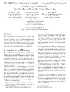
To connect users and the development organization an Experience Forum, as presented in [13] can be used to facilitate feedback: An Experience Forum is integrated into the client application. At each step, the user is shown the handbook and experiences of other users relevant to the current step. Additionally, the user can submit feedback to the activity she or he is currently performing. Feedback can be of three types: Bug Reports: Users can instantly submit software defects they find. These can be propagated into the development process. Bug Reports affect only one Use Case as they will address defects in a screen which affects the current user. Feature Requests: Users observe features which would improve their daily tasks during their work. They can submit these feature requests via the Experience Forum as well. Those requests are fed as well into the development process. Process Shortcomings and Improvements: Users can leave comments concerning the business process. For example, documents which are forwarded to them but never used can be criticized. Such feedbacks affect the overall process. The development organization together with the business process designers need to take those comments into account. Process Experiences: The users are actually the ones who perform the business process. They have experiences how to interpret certain rules and how to handle unexpected situations. If they have mastered a new situation, they can enter their newly gained experience into the Experience Forum and let all other users profit from it. This kind of feedback founds a new Community of Practice among the relevant users. The main advantage of an Experience Forum is the possibility to automatically capture the context of feedback in a SOA: The system knows which function in which process is currently performed by which user because the service composition already has this information. Therefore, the feedback can automatically be assigned to the underlying business function and retrieved whenever another user performs the same business function. As stated above, the context contains the reference to the business process position it was made in and the submitter. Additionally, the language is stored in the context. Only feedback understandable by a certain user is retrieved and presented. Figure 2 shows an Experience Forum integrated into a client application. On the right hand side, it is readily accessible and usable with only some mouse clicks. This low threshold is very important in order to improve user acceptance. If the Experience Forum was somewhere hidden in the menus or hard to use, it would not be put into use by the users.
5
Example Project
The example project is taken from a university project. The software and the process for managing student exams and thesis had to be newly designed. Partic-
22
Dealing with User Requirements and Feedback in SOA Projects
7
Fig. 2. Example screen shot of an Experience Forum
ipants of this process are the professors, the personnel of the Academic Examination Office, and of course the students. Because no formalized business process was in place, Use Cases have been used to elicit and document the requirements from the point of view of each actor. An extract of the Use Cases are illustrated in figure 3. Using the described algorithm these Use Cases are transformed into an EPC model, which is illustrated in figure 4. Afterwards, the system has been developed and put into production. Example feedback given via the Experience Forum could have been e.g.: – The secretary of the Academic Examination Office observes that a mark 2.7 of an exam is incorrectly rounded to 3.0 instead of 2.75 (bug report). – A professor observes, that she can access the student’s name in the application. However, the email address is not visible to her. This feature would be handy for contacting the student. Currently, she has to ask the students for the email addresses which she has to store separately (feature request). – A student, who already registered for a thesis, had to choose a topic for his thesis first. However, the topic has not been finalized before due to organizational issues. It would be good, if theses could be registered without a topic, which has to be inserted later on (process improvement). – It took another professor a long time to decide how to grade a problematic thesis. He put his criteria and his reasoning into the Experience Forum. A new professor read the comment, which helped her grading her first thesis at the new university (process experience).
23
8
Daniel L¨ ubke and Eric Knauss
Use Case
#1: Student applies for Thesis
Primary Actor
Student
Stakeholders
Student: wants to apply easily Secretary (Academic Examination Office): wants easy to use/read forms for further handling registration
Minimal Guarantees
none
Successs Guarantees
Application is submitted
Preconditions
none
Triggers
Student wants to write thesis
Main Success Scenario
1 Student fills out form with personal data 2 Student submits form to Academic Examination Office
Extensions
Use Case
#2: Academic Examination Office approves Thesis
Primary Actor
Secretary (Academic Examination Office)
Stakeholders
Secretary (Academic Examination Office): wants easy to use/read forms for further handling registration Manager (Academic Examination Office): wants short handling times
Minimal Guarantees
Student's data are handled according to regulations
Successs Guarantees
Student may write Thesis
Preconditions
none
Triggers
Application is submitted
Main Success Scenario
1 Secretary checks if student has 80% of Credit Points
none
2 Secretary approves application Extensions
1a If Student has less than 80% of Credit Points then Secretary denies Application
Fig. 3. Use Cases for describing the new System
The first three feedbacks have been fed into the development cycle. How to proceed from having the feedback to actually using it, is dependent on the development methodology used. In the next section, integration into several development processes is presented.
6
Development Process Integration
While an Experience Forum is a technical mechanism for collecting and facilitating user feedback, it needs to be carefully integrated into the development process used within the project to be successful. The Experience Forum is to be used after the first release used by real users. This will normally be the first production release but can also be a preview version in use by a limited number of users. Figure 5 shows an overview of the activities in requirements engineering. The following list explains how the Experience Forum can generally be integrated into each activity: Requirements Analysis (or: system analysis) Elicitation The Experience Forum supports the activity of requirements elicitation by encouraging users to write down their issues. Nevertheless a requirements engineer has to sort the issues by their different types: requirements that affect the software (real requirements like bug-reports or new requirements), requirements that affect the business model and issues that support the business process with domain knowledge. Interpretation In this activity the requirements engineer has to refine the raw requirements to make them tangible (ideally making them testable). The benefit of using the Experience Forum is the link between the raw
24
Dealing with User Requirements and Feedback in SOA Projects
Student wants to write thesis
Student fills out form with personal data
Student looks through list of available topics
Ok: Student fills out form with personal data
Ok: Student looks through list of available topics
Student submits form to Academic Examination Office
Student chooses most interesting topic
Application is submitted
Ok: Student chooses most interesting topic
Secretary checks if student has 80% of Credit Points
Student asks supervisor to get the topic
Student has less than 80% Credit Points
Secretary denies application
Ok: Secretary denies application
Ok: Secretary checks if student has 80% of Credit Points
Secretary approves application
Student has picked a topic
Student may write thesis
V
XOR
Supervisor hands out topic
...
Fig. 4. Business Process extracted from Use Cases
Fig. 5. Overview of requirements engineering and its activities.
9
25
10
Daniel L¨ ubke and Eric Knauss
requirements and the location in the business process or software application it applies to. This helps the requirements engineer to identify stakeholder. representatives. The ambiguities and inconsistencies in the comments and experiences still have to be clarified by the requirements engineer. Negotiation The identification and resolution of inconsistencies and conflicts in the requirements as well as the prioritization of requirements define this activity. Obviously this activity demands flair, a fact that is even aggravated by the transparency the Experience Forum introduced (see section 6.3) – especially, if bugs and feature requests are assigned a low priority. Documentation This activity transforms the raw requirements of the Experience Forum into a form best suited for the software development process. Verification / validation The inspection of form and content is supported by the Experience Forum’s context information. Requirements Management All activities that deal with requirements management should incorporate the Experience Forum: Change Management Solved issues have to be labeled or deleted, issues that apply to parts of the software or business process that have been changed must be revised. Tracing The Experience Forum contains valuable information about the context of requirements. So solutions that aim at traceability should take the Experience Forum in account, too. The development process itself is supposed to be an iterative development process. Since feedback can only be collected from a first working software version, improvements originating from the Experience Forum can consequently only be added from the second iteration or software version onwards. 6.1
A Document-Based Process
An Experience Forum can enhance the communication flow between the users, the responsible persons for requirements and the development team in documentbased development processes. The new communication structure can be seen in figure 6.1. Our example process defines the role of the experience and requirements engineer. This role is responsible for refining the working experiences in the forum into requirements. Another responsibility is to sort the new requirements and give them as change request either to the process designers or to the software change control board. The process designers will adjust the business process which will normally generate additional change requests for the software. The software change control board gives the clearance for the change requests to the software developers. Now the new release of the software is created. Before it can finally be made available for the users, the experience and requirements
26
Dealing with User Requirements and Feedback in SOA Projects
11
Fig. 6. Experience Base integrated into a SOA project
engineer has to adjust the experiences of the forum to the new release. At this point a refinement of the experiences in the Experience Forum of the old release into best practices (and similar activities proposed in [2]) can be made. For the requirements management process it is important to mark the experiences that lead to the new requirements as closed issues at this point. Developers will normally have read access to the information necessary to complete their assignments and the users can access their information as well, possibly forming a Community of Practice. With the introduction of the new software release the next iteration is started. The Experience Forum is seeded with the refined experiences from the last release and the software reflects the latest version of the business process. 6.2
Scrum
Whenever a development process is in place which is not iterative by default, the Experience Forum approach cannot be used because it requires multiple iterations to incorporate the feedback into the later software versions. When organizations have non-iterative processes in use, one way to make these development processes iterative is wrapping them in Scrum. Scrum [3] is an agile management methodology, partitioning the whole development project into 30 day iterations called Sprints. The product-owner maintains a list of requirements ordered by priorities, the product-backlog. The development-team takes as much of the requirements from this list as they want to implement in the next 30 days and puts them into the sprint-backlog. Within a sprint the requirements in this sprint-backlog cannot be changed from outside the team. However, the product-owner may append new requirements to the product-backlog during a sprint. Therefore, the product-owner is responsible for requirements analysis and to incorporate information gathered by the Experience Forum into the productbacklog. Due to the fixation of requirements during a Sprint, information gathered by the Experience Forum can only be implemented during the third or a following Sprint.
27
12
6.3
Daniel L¨ ubke and Eric Knauss
Advantages and Pitfalls
The concept of an Experience Forum has – independent of the development process – many advantages: Users are able to give easily and quickly feedback during their daily work. The threshold is thereby reduced improving the probability of getting feedback. While the user submits information, the application’s and process contexts are automatically captured: Issues are linked to the user interface and the current process element. This is especially easy if - as in our prototype system - the user interface is generated from the process description. Therefore, the system can automatically link between user interface elements and the part of the process it supports. Requirements Engineers or similar roles are thereby supported in the requirement interpretation because they can better understand and realize the feedback without needing to recreate the whole situation which normally is not well-described. This also applies to the developers: Whenever they get a defect assigned, they can also see the context to which the defect applies to. However, Experience Forums - if used wrongly - can have negative effects: If users are willing to give feedback to the software and processes they are using and they are affected by, they expect that things are getting better. If the feedback is not used or seems to be not used due to long response times, the motivation of the user-base may degrade and acceptance may decrease. These risks must be guarded against which in essence means the process integration must be carefully done. Especially, a user notification, what status the user’s feedback has, if and when it will be considered, can mitigate that risk. Furthermore, one should be aware of that an Experience Forum can only assist in making existing processes and software incrementally better but will not lead to radically new processes. If a company wants to completely re-engineer their processes it may not be the tool of choice. However, in this case an already used Experience Forum can be beneficial: Process Designers can use the gathered experiences and information to learn from prior weaknesses and problems.
7
Related Work
Profiting from information contained in Use Cases for other models and development phases has always been a goal in software development projects, which often deal with business processes. Cockburn himself only mentions the possibility of applying Use Cases for deriving business processes. He offers a template in [4] but no rules or advise how to proceed from there. The field of model-driven development has tried to combine the concept of Use Cases with its models. Instead of tabular and textual descriptions, UML sequence diagrams or similar models are used [9]. A Use Case is consequently denoted in Use Case diagrams and refined in other models thereby eliminating the textual description. This can pose a problem when communicating with nontechnical users. A process for UML-based development of business processes
28
Dealing with User Requirements and Feedback in SOA Projects
13
is given in [14]. Missing from such approaches are capabilities for expressing control flow between Use Cases and therefore the generation of business process models. The only way to achieve business process generation is to explicitly model the control flow between Use Cases in at least one additional model. With the introduction of Use Case Charts and their formalization [17], it is possible to define control flow dependencies between Use Cases and refine them in UML. From such descriptions other models can be generated, e.g. Hierarchical State Machines [18]. The Experience Forum presented in this paper has many similarities to the Experience Base in Basili’s Experience Factory [2]. In fact, it offers the same functionality, e.g. it helps users finding applicable experiences by the context of their work. The Experience Base in a Learning Software Organization however supports the software development-team to optimize their development process. Note that the Experience Base is maintained by developers for developers. In contrast, our Experience Forum serves the users of the software as an annotated online manual and supports them to optimize their daily work. As a by-product it helps with the elicitation of requirements for the next release: the parts of the software that have the most comments are good candidates for the next changes. The fact that the Experience Forum is maintained by the users, but leveraged by users and developers implies new chances and threats. Change Management is also related to the Experience Forum. When enough comments exist in the Experience Forum, they have to be transformed into new requirements. These requirements have to be introduced into the software development process. Our approach does not strive to replace traditional change management. Instead it supports generating the new requirements that represent the changes in change management. Closer to the intended purpose of the Experience Forum are feedback facilities nowadays commonly found in many software products (like e.g. in Microsoft Windows, KDE or Mozilla). These facilities also try to collect information about when and how potential bugs and unwanted situations (like maintenance error or malfunction) occurs. Similar to our approach they depend on the help of the users. The Experience Forum is different in that it allows the users to see reports of other users as well. Therefore, users can profit from tips and help each other to avoid certain misconducts of the information system. Of course this transparency makes bugs highly visible throughout the user community. This is certainly an unwanted effect for many software products. In section 6.3 we described how this effect can be used to positively influence the acceptance and maintenance of the software. The idea of giving users the chance to help themselves is neither surprising (users are experts in their domain) nor new. There is a tendency to introduce this idea for example in online software documentation. In the online documentation of Postgresql or PHP the user can annotate the documentation and enrich it with examples or longer explanations. This approach has many similarities to online communities like forums, wikis or blogs. The difference is that the context of the observation is included in the editable online documentations as well as
29
14
Daniel L¨ ubke and Eric Knauss
in our Experience Forum. When an explanation in an online documentation is wrong, users will notice this fact while working in this chapter. They can quickly annotate the misleading passage. If users have to write their comments into a simple forum, they normally formulate them as general questions or solutions. The problem is that there is no link to the bad documentation that caused the problem. Therefore, the forum will evolve in parallel to the documentation which introduces new efforts to avoid inconsistencies. In contrast editable online documentation present documentation and its user annotations together, preserving the context of the comments. Our approach takes the user commented documentation one step further. Not the documentation is annotated but the application itself.
8
Conclusions and Outlook
Within this paper, a requirements round-trip from the initial requirements for SOA projects to the integration of user feedback has been presented. Since SOA tries to combine the business side and the technical side, SOA projects must integrate business process modeling and traditional requirements engineering. An approach how to derive business processes from Use Cases and vice versa has been presented in order to save effort in such environments which can be useful for more general process-driven projects as well. However, the initial requirements will not be perfect – despite all the effort to do them “right”. Fine-tuning can be done in iterative development processes, when user input is available. However, asking hundreds of users for their opinion and their problems is practically not feasible. Instead, we propose an Experience Forum, which is integrated into the client application. Users can easily enter their feedback and retrieve others’ experiences. This way, not only the development team can better understand and fix problems, but also the users can share with each other their experiences related to their daily work, which is carried out using the application. Currently, there is no other approach known to us, which tries to cover the whole requirements life-cycle for SOA projects. In our opinion, integrating initial requirements and constant feedback are the basis for sustainable successful SOA projects. The initial requirements should be formed of focused requirements in the form of Use Cases and business processes, which offer an overview about the system and are the foundations for easy implementation of service compositions. The next step is to combine the Experience Forum with existing approaches for generating user interfaces. This would result in a platform which is very flexible and easy to change. That way, changes in business processes, possibly initiated by the Experience Forum, can easily be incorporated into a strong and enduring SOA implementation.
References 1. Tony Andrews, Francisco Curbera, Hitesh Dholakia, Yaron Goland, Johannes Klein, Frank Leymann, Kevin Liu, Dieter Roller, Doug Smith, Satish Thatte, Ivana
30
Dealing with User Requirements and Feedback in SOA Projects
2.
3. 4. 5. 6.
7. 8.
9. 10.
11. 12.
13. 14.
15. 16. 17. 18.
15
Trickovic, and Sanjiva Weerawarana. Business Process Execution Language for Web Services Version 1.1, May 2003. V.R. Basili, G. Caldiera, and H.D. Rombach. The Experience Factory. In John J. Marciniak, editor, Encyclopedia of Software Engineering, volume 1, pages 469–476. John Wiley & Sons, 1994. Mike Beedle and Ken Schwaber. Agile Software Development with Scrum. Prentice Hall, 2001. Alistair Cockburn. Writing Effective Use Cases. Addison-Wesley, 14th edition, August 2005. Christian Crisp. Konzept und Werkzeug zur erfahrungsbasierten Erstellung von Use Cases. Master’s thesis, Leibniz Universit¨ at Hannover, October 2006. Dimitri Diegel. Konzept zur Verkn¨ upfung von Use Cases mit ereignisgesteuerten Prozessketten. Master’s thesis, Gottfried Wilhelm Leibniz Unversit¨ at Hannover, September 2006. Gerhard Fischer. Symmetry of ignorance, social creativity, and meta-design. KBS Special Issues C&C99, 13(7–8):527–537, 2000. Florian Gottschalk, Michael Rosemann, and Wil M.P. van der Aalst. My own process: Providing dedicated views on EPCs. In Markus N¨ uttgens and Frank J. Rump, editors, EPK 2005 - Gesch¨ aftsprozessmanagement mit Ereignisgesteuerten Prozessketten, pages 156–175, 2005. Object Management Group. Unified Modeling Language: Superstructure. WWW: http://www.omg.org/cgi-bin/doc?formal/05-07-04, 2004. Matthias Kloppmann, Dieter Koenig, Frank Leymann, Gerhard Pfau, Alan Rickayzen, Claus von Riegen, Patrick Schmidt, and Ivana Trickovic. WS-BPEL Extension for People BPEL4People A Joint White Paper by IBM and SAP. IBM/SAP, August 2005. Daniel L¨ ubke. Transformation of Use Cases to EPC Models. In Proceedings of the EPK 2006 Workshop, Vienna, Austria, 2006. Daniel L¨ ubke, Tim L¨ uecke, Kurt Schneider, and Jorge Marx G´ omez. Using EPCs for Model-Driven Development of Business Applications. In Franz Lehner, Holger N¨ osekabel, and Peter Kleinschmidt, editors, Multikonferenz Wirtschaftsinformatik 2006, volume 2, pages 265–280. GITO Verlag, 2006. Daniel L¨ ubke and Kurt Schneider. Leveraging Feedback on Processes in SOA Projects. In Proceedings of the EuroSPI 2006, pages 195–206, 2006. Bernd Oestereich, Christian Weiss, Claudia Schr¨ oder, Tim Weilkiens, and Alexander Lenhard. Objektorientierte Geschftsprozessmodellierung mit der UML. d.punkt Verlag, 2003. W.J. Rittel and M.M. Webber. Planning Problems are Wicked Problems, pages 135–144. John Wiley & Sons, 135-144, New York, 1984. Kurt Schneider and Daniel L¨ ubke. Systematic Tailoring of Quality Techniques. In Proceedings of the World Congress of Software Quality 2005, 2005. Jon Whittle. A Formal Semantics of Use Case Charts. Technical Report ISE-TR06-02, George Mason University, http://www.ise.gmu.edu/techrep, 2006. Jon Whittle and Praveen K. Jayaraman. Generating Hierarchical State Machines from Use Cases. In Martin Glinz and Robyn Lutz, editors, Proceedings of the 14th IEEE International Requirements Engineering Conference, pages 19–28. IEEE Computer Society, 2006.
31
Semantic Model-Driven Development of Service-centric Software Architectures Claus Pahl and Ronan Barrett Dublin City University School of Computing Dublin 9, Ireland [cpahl|rbarrett]@computing.dcu.ie
Abstract. Service-oriented architecture (SOA) is a recent architectural paradigm that has received much attention. The prevalent focus on platforms such as Web services, however, needs to be complemented by appropriate software engineering methods. We propose the model-driven development of service-centric software systems. We present in particular an investigation into the role of enriched semantic modelling for a modeldriven development framework for service-centric software systems. Ontologies as the foundations of semantic modelling and its enhancement through architectural pattern modelling are at the core of the proposed approach. We introduce foundations and discuss the benefits and also the challenges in this context. Keywords: Service-oriented Architecture, Service Processes, Model-Driven Development, Semantic Modelling, Ontologies, Architectural Patterns.
1
Introduction
Service-oriented architecture (SOA) has been successfully deployed as an architectural paradigm in recent years [2]. The dominance of the Web services platform in distributed systems development and deployment has given a boost to SOA as an approach to software architecture [3]. Current solutions to description and collaboration languages and to platform technologies such as protocols need to be embedded into an adequate software engineering methodology. The SOA approach creates some specific requirements for supporting software engineering methods [23]. Firstly, services are used ’as is’, with providers and consumers often coming from different organisations. This requires detailed descriptions of functional and non-functional aspects in an mutually agreed format Secondly, service descriptions need to be based on rich modelling languages, in order to support their automated discovery and composition. Thirdly, reuse is a central aim of service technology that needs to be addressed on the level of individual services as well as service compositions. Model-driven development (MDD) is an established and widely used approach to software development that aims at cost-effective automation and improved maintainability through abstract modelling. The recent standardisation
32
of the approach, Model-Driven Architecture (MDA), has emphasised the importance of this approach for the software sector [1]. MDA proposes abstract modelling combined with the automatic generation of code from these models. We propose an MDD approach for SOA, aiming to support the development of service-centric software systems. We will explore foundations (in form of ontologies) and design methods (in form of architectural patterns). Specifically, we deem two specific methods necessary to satisfy the specific requirements: – semantic modelling supported through ontologies, i.e. logic-based knowledge representation frameworks, in order to support rich modelling constructs, reasoning, and formal semantics [15]. – pattern-based modelling supported through architectural patterns in order to add higher levels of abstraction and to enable the reuse of useful architectural styles and designs. Our contribution is twofold. Firstly, a discussion of central techniques for MDD for service-centric software systems. Secondly, an outline of an ontology-based framework for MDD of service-centric software systems involving architectural patterns as central design technique – these are patterns (or styles) of architectures, typically different from design patterns [24]. Our investigation shall lead towards an emerging service engineering discipline. We divide our discussion into three aspects. We start with modelling of service functionality supported by ontologies in Section 2. Modelling of nonfunctional aspects and the use of patterns is then the topic of Section 3. We discuss ontologies and patterns in a wider context of service engineering in Section 4. We end with a discussion of related work and some conclusions.
2
Modelling of Service Functionality
Modelling of software often focuses on functional aspects such as the software architecture or behavioural aspects of a software system. This traditional focus of software modelling shall also be discussed in this section and the specific modelling needs for service-centric software systems shall be discussed. Abstraction and automated code generation are the pillars of model-driven development [4]. We investigate the role that ontologies can play for the support of these pillars in the context of functional aspects of service-oriented architecture. In terms of the OMG’s MDA framework, we are going to address modelling at the platform-independent (PIM) layer and transformations form there into the platform-specific layer (PSM). 2.1
Semantic Service Modelling
UML is the most widely used software modelling notation. An integration of the proposed semantic modelling approach with UML is important for two reasons: – UML provides a rich combination of individual visual modelling languages. These visual interfaces can be adapted to support service modelling.
33
– A vast amount of UML models for a broad range of application contexts exist. Reusing and integrating these is almost a necessity. UML is limited in particular in terms of the constraints on software systems that can be expressed. OCL, the Object Constraint Language, is a UML extension that allows semantic constraints such as pre- and postconditions and invariants for operations and classes to be expressed [17]. While a wide range of powerful logics have been available to support constraint formulation and reasoning, the recent advent of the Semantic Web with its ontology-based foundations have make ontologies a promising candidate for enhanced semantic modelling in the context of the Web platform [16]. – Ontologies provide a logical language, for instance based on description logic [14], with its reasoning support. – Ontology languages, such as OWL, are the knowledge representation languages of the Web [16] that enable XML-based syntactical interoperability and knowledge sharing and exchange. For these reasons, the semantic modelling of Web services is ideally supported by ontologies, as the research focus on semantic Web services shows [7, 12]. Besides providing a rich semantic modelling notation – which can, as proposed, be augmented by a UML-style interface – ontologies can support design activities such as composition, and act as formal semantics for the overall model-driven development integrating modelling and transformations. WSMO [10] and OWL-S [9] are the two predominant examples of service ontologies. Service ontologies are ontologies to describe Web services, aiming to support their semantics-based discovery in Web service registries. The Web Service Process Ontology WSPO [13] is also a service ontology, but its focus is the support of description and reasoning about service composition and service-based architectural configuration. An important current development is the Semantic Web Services Framework (SWSF), consisting of a language and an underlying ontology [21], which takes OWL-S work further. The FLOWS ontology in SWSF comprises process modelling and is like WSPO suited to support semantic service modelling within the MDA context. While the early service ontologies have focused on individual services and their properties – OWL-S and WSMO – more recent attention has been paid to service process ontologies – SWSF and WSPO – which focus on the composition of services to form processes. A different type of ontology, supporting composition activities and the formulation of collaborating servcies as processes, is needed for the composition aspect [8]. 2.2
Service Composition
In order to support the development of service architectures, more than just description notations are needed. Specific activities such as service discovery or process composition need to be supported through anaysis and reasoning techniques [22]. We look here into ontology-based support for service composition.
34
valid(sessionID)
result=balance(account)
vaild(sessionID)
not valid(sessionID) {account}
{user,account}
balance enquiry
{balance} {sessionID}
login
{void}
logout {sessionID}
valid(user,account) choice
{account, destination, amount}
money transfer
vaild(sessionID) ∧ balance(account)>0
{void} true
balance = balance@pre -amount
Fig. 1. Semantic Service Process Model based on UML Activity Diagrams.
Service composition is a logical composition where an abstract service process based on individual services is assembled [6]. We have developed the WSPO composition ontology – Web Services Process Ontology – in order to support the semantically correct composition of services [13]. Ontologies in general consist of concepts that represent objects, process, etc. and relationships between these concepts. Services (and processes) in the WSPO ontology are not represented as concepts, but as relationships denoting accessibility relations between states of a software system. – Ontology concepts in this approach are states (pre- and poststates), parameters (in- and out-parameters), and conditions (pre- and postconditions). – Two forms of relationships are provided in the ontology. The services or processes themselves are called transitional relationships. Syntactical and semantical descriptions here parameter objects (syntax) and conditions (semantics) are associated through descriptional relationships. WSPO provides a standard template for service and service process description – applied in Fig. 1 to express a composite bank account process consisting of operations provided by services like ’balance enquiry’ or ’money transfer’. This application is based on four individual services, each described in terms of input, output, precondition, and postcondition. Syntactical parameter information in relation to the individual activities – to be implemented through service operations – and also semantical information such as pre-conditions are attached to each activity as defined in the template. The following textual representation summarises the syntactical aspects in a traditional IDL-style interface format: application AccountProcess services login (user:string, account:int) : ID balance enquiry (account:int) : currency money transfer (account:int, destination:int, amount:currency) : void
35
logout (sessionID:ID) : void process login; !( balance enquiry + money transfer ); logout The services are composed to a process, here using the combinators sequence (;), iteration (!), and choice (+) in the textual representation above, which is also visualised in UML notation in Fig. 1. WSPO can be distinguished from traditional service ontologies by two specific properties. Firstly, based on an extension of description logics [14], it adds a relationship-based process sublanguage enabling process expressions based on iteration, sequential and parallel composition, and choice operators. Secondly, it adds data to processes in form of parameters that are introduced as constant process elements into the process sublanguage. This ontological representation in WSPO is actually an encoding of a simple dynamic logic (a logic of programs) in a description logic format [13], allowing us to avail of modal logic reasoning about processes in this framework. For example, in order to implement a bank account process, an implementation for a money transfer service with input parameter amount (assumed to be always positive) needs to be integrated. For any given state, the process developer might require (using the balance enquiry) service:preCondition rdfConstr="balance() > amount" service:postCondition rdfConstr="balance() = balance()@pre - amount" which would be satisfied by a provided service service:preCondition rdfConstr="balance() > 0" service:postCondition rdfConstr="balance() = balance()@pre - amount and lastActivity = ’transfer’" The provided service would weaken the required precondition assuming that the transfer amount is always positive and strengthen the required postcondition as an additional result (lastActivity) is delivered by the provided service. This matching notion, which is important for service discovery support, is implemented in WSPO based on a refinement of the standard subsumption relation of description logics towards a consequence inference rule from dynamic logic. We have chosen WSPO here instead of the SWSF. The more recent SWSF is an equally suitable service process ontology, providing actually a wider range of modelling feature, which would make it the better choice once sufficient tool support is available. For the moment, WSPO as a more focused and decidable ontology is the better choice in terms of tractability of the approach. 2.3
Transformation and Code Generation
Automated code generation is one of the central objectives of MDD. Two types of generation of code in service platform-specific languages are relevant here – Executable code generation: in the context of SOA, code generation essentially means the generation of exectuable service processes. WS-BPEL
36
(BPEL, 2004) has emerged as the most widely accepted process execution language for Web services. Within MDD, code generation is usually specified through transformation rules. – Abstract description generation: a central element of SOA is service discovery based on abstract service descriptions. OWL-S, WSMO, or SWSF would be suitable ontology frameworks that support description and discovery. An overview of some of the transformation rules for a WSPO to WS-BPEL transformation to generate executable code is presented below. WSPO defines a simple process language that can be fully translated into WS-BPEL. BPEL process partners are the consumers and the different service providers – the WSPO specification is already partitioned accordingly. The WSPO process combinators can also be mapped directly onto the BPEL flow combinators. The principles of this transformation can be characterised as follows: – The WSPO process relationships can be mapped to BPEL processes. – For each process, a BPEL partner process (consumer and server) is created. – Each process expression is converted into BPEL-invoke activities at the client side and BPEL-receive and -reply activities at the server side. – The process combinators ’;’, ’+’, ’ !’, and ’||’ are converted to the BPEL flow combinators sequence, pick, while, and flow, respectively. A schematic example in the declarative transformation language QVT shall illustrate these principles for WSPO-to-BPEL transformations1 : transformation WSPO_to_WS-BPEL (wspo : WSPO, bpel: WS-BPEL) { top relation TransRelationship_to_Process /* maps trans. relationships to processes */ { checkonly domain wspo w:TransRel {name = pn} enforce domain bpel b:Process {name = pn} } where { RelExpr_to_ProcessExpr(w); } relation RelExpr_to_ProcessExpr /* map each process expression recursively */ { domain wspo r:Relationship { e1 = e:LeftExpr {}, e2 = e:RightExpr {}, op = c:Combinator {} 1
Although its standardisation is not completed and no tool support is currently available for the declarative specifications, QVT will be an essential tool for the implementation of our approach in the near future.
37
} domain bpel p:Process { process = p:Process {left=e1, pr=op, right=e2}, client = pe:ProcessExpr {invoke=op(e1,e2)}, server = pe:ProcessExpr {receive=(op,e1,e2), reply=op(e1,e2)} } when { CombinatorMapping(op) and ProcessPartnerCreation(p); } where { RelExpr_to_ProcessExpr(e1) and RelExpr_to_ProcessExpr(e2); } } } We do not present the WS-BPEL representation here, since with the exception of some reformulations of operators and the additional verbosity of the XML-based formulation, the process itself is similar to the WSPO representation. The second transformation and code generation context relates to service description and discovery. The Web Services platform proposes a specific architecture based on services, which can be located using abstract service information provided in service registries. The description of services – or service processes made available as a single service - ideally in semantical format is therefore of central importance. Information represented in the process model and formalised in the service process ontology can be mapped to a service ontology. This transformation would only be a mapping into a subset of these ontologies, since they capture a wide range of functional and non-functional properties, whereas we have focussed on architecture-specific properties in WSPO. We chose WSMO as the target. An overview of the transformation rules from WSPO to WSMO is outlined below. Some correspondences between the two ontology frameworks guide this transformation. WSPO input and output elements correspond to WSMO message-exchange patterns, which are used in WSMO to express stimuli-response patterns of direct service invocations, and WSPO pre- and postconditions correspond to their WSMO counterparts. – WSPO process relationships are mapped to WSMO service concept and fill messageExchange and pre- and postCondition properties accordingly. – WSPO in/out-objects are mapped to WSMO messageExchange descriptions. – WSPO pre- and postconditions are mapped onto their WSMO counterparts. A QVT formulation would be similar to the WSPO-to-BPEL transformation. 2.4
Discussion
This section has demonstrated the role that ontologies can play in model-driven development of service-centric software systems. They can provide a semantic modelling framework in particular for the Web platform due to the support of
38
ontologies through the Semantic Web initiative. They can act as a foundational layer to define visual modelling languages, to support composition tasks, and to enable automated transformations. While we have discussed the application of ontologies for functional aspects of software systems specification such as pre- and postconditions, their scope stretches further to also include non-functional aspects such as general descriptions, cost models, security requirememts, etc. . Non-functional aspects shall be addressed in depth in the next section.
3
Modelling of Non-Functional Service Aspects
The deployment model of services in general and Web services in particular is based on the idea of service provider and service consumer being business partners. This constellation requires contracts to be set up, based on servicelevel agreements (SLAs). While of course functional characteristic of services are vital elements in these SLAs, non-functional aspects – ranging from availability and performance guarantees to costing aspects – are equally important and need to be captured in SLAs to clearly state the quality-of-service (QoS) obligations and expectations of provider and consumer. This discussion will show that ontologies are an adequate modelling notation, but that additional techniques are needed to address modelling, in particular if functional and non-functional aspects are integrated. We will introduce distribution patterns, again at the architectural level, to provide a framework for higher levels of abstraction beyond the service process composition [26]. These patterns will add a widely used method centering around the notion of reuse of abstract architectural designs and models to semantic modelling. A quality dimension is added through quality attributes associated to these distribution patterns. 3.1
Distribution and Service Topology
Ontologies, the focus of the previous section, can deal with the abstract specification of QoS properties by providing an adequate vocabulary based on a variety of relationships. A mere statement of required QoS properties is therefore often not sufficient to actually guarantee these properties. However, there are links between functionally-oriented models and QoS properties. We look at distribution properties of service-centric software systems to illustrate this. Distribution, i.e. the consideration of the location of services in a complex system, affects qualities of the software systems such as reliability, availability, and performance. We use the term service topology to refer to the modelling of service compositions as collaborating entities under explicit consideration of the distribution characteristics. 3.2
Service Topology Modelling
Based on experience with the design and implementation of service-centric software systems, a number of standard architectural configurations have emerged
39
[25, 27, 29, 31]. These include centralised configurations such as the Hub-andSpoke or decentralised ones such as Peer-to-Peer architectures. These standard configurations can be abstracted into architecture-lavel distribution patterns for the SOA platform. The goal is to enable the generation of architecturally flexible Web service compositions, whose Quality of Service (QoS) characteristics can be evaluated and altered at design time. Distribution pattern modelling expresses how the composed system is to be deployed from the architectural perspective [18]. Having the ability to model, and thus alter the distribution pattern, allows an enterprise to configure its systems as they evolve, and to meet varying non-functional requirements. There is a subtle difference between two of the modeling aspects within a Web service composition, namely workflows and distribution patterns. Both aspects refer to the high level cooperation of components, termed a collaboration, to achieve some compound novel task. We consider workflows as compositional orchestrations, whereby the internal and external messages to and from services are modelled. In contrast, distribution patterns are considered compositional choreographies, where only the external messages flow between services is modelled. Consequently the control flow between services are considered orthogonal. As such, a choreography can express how a system would be deployed. The internal workflows of these services are not modelled here, as there are many approaches to modelling the internals of such services. 3.3
Modelling Process and Transformation
This component of our framework comprises a catalog of distribution patterns, which may be applied by software architects to Web service compositions [18]. Distribution patterns express how a composed system is to be assembled and subsequently deployed. Each of the patterns in the catalog has associated Quality of Service (QoS) characteristics, exhibited during execution of Web service compositions. The catalog enumerates the QoS characteristics of each of the patterns, enabling the architect to choose a pattern appropriate to the non functional requirements of a given composition. The patterns are split into three categories, core patterns, auxiliary patterns and complex patterns. Core patterns represent the simplest distribution patterns most commonly observed in Web service compositions. Auxiliary patterns are patterns which can be combined with core patterns to improve a given QoS characteristic of a core pattern, the resultant pattern is a complex pattern. This catalog assists software architects in choosing a distribution pattern for a given application context. The catalog is outlined briefly below: – Core Patterns: Centralised, Decentralised – Auxiliary Patterns: Ring – Complex Patterns: Hierarchical, Ring + Centralised, Centralised + Decentralised, Ring + Decentralised
40
We describe one pattern to illustrate distribution patterns and their QoS relevance. The Centralised pattern, or Hub-and-Spoke pattern, manages the composition from a single location, normally the participant initiating the composition. Here is the service choreography: application Centralised services Hub ( in : inType) : outType Spoke1 ( . . . ) : . . . ... Spoken ( . . . ) : . . . process Hub ||D ( Spoke1 || . . . || Spoken ) The composition controller (the hub) is located externally from the service participants to be composed (the spokes), indicated through the distribution annotation at the parallel composition operator. Spokes would internally invoke the Hub using the given Hub interface. The external spoke interfaces are not relevant here. This is the most popular and usually default distribution configuration for service compositions. The advantages of the pattern in terms of QoS aspects are: – Composition is easily maintainable, as composition logic is all contained at a single participant, the central hub. – Low deployment overhead as only the hub manages the composition. – Composition can consume participant services that are externally controlled. Web service technology enables the reuse of existing services. – The spokes require no modifications to take part in the composition. Web service technology enables interoperability. The main disadvantages are: – A single point of failure at the hub provides for poor reliability/availability. – A communication bottleneck at the hub restricts scalability. SOAP messages have considerable overhead for message deserialisation and serialisation. – The high number of messages between hub and spokes is sub-optimal. SOAP messages are often verbose resulting in poor performance for Web services. – Poor autonomy in that the input and output values of each participant can be read by the central hub. A distribution pattern language DPL provides the constructs for the internal representation of a distribution pattern. The DPL, which similarly to WSPO has a UML interface based on activity diagrams, provides: – control flow: information about the nodes and edges that define the control flow structure, on which interactions between individual services take place. – data flow: information about which data is flowing in which direction in an interaction between services. DPL is a high-level service process modelling language that provides the foundations for pattern-based service architecture.
41
3.4
Discussion
While we have looked at architectural patterns to model the functional side in the previous section, i.e. the structural and behavioural aspects of software, we have focused here on their potential in the context of non-functional properties. Distribution patterns imply non-functional properties of service-centric software systems. The choice of these patterns in particular determines performance, availability, and reliability charateristics of the software system itself.
4
A Service Engineering Perspective
Issues arising from the cooperation between organisations and the integration of systems across organisations leads to another couple of issues relevant to our discussion of ontologies and patterns for service-centric software engineering. This discussion of a wider context helps us to determine the potential, but also the challenges for the use of ontologies and patterns. 4.1
Cooperation
The cooperation between service providers and consumers is necessary for serviceoriented computing. This requires at least interoperability of formats of all artifacts involved, in particular for models. Contracts stating service-level agreements are the actual documents, which might refer to additional documents and models internally. Ontologies have the potential to provide a common vocabulary that would allow the automated processing of these contracts. The wider aim within a service-centric software engineering discipline is an integrated value chain for software services that brings together all participants in the production process – for instance through interoperable deployment infrastructures, but also through contract and model exchange. 4.2
Trust
Trust is a central problem for collaborating partners that are initially often unknown to each other. In the context of automated service compositions, detailed model-based contracts can capture the obligations and expectations in terms of functional and QoS service properties, but do not suffice on their own. Interoperability is an enabler of integrated value chains, but only trust will make this business scenario work ultimately. At the core of trust mechanisms are composition and description techniques, for instance our ontology-based modelling techniques. Quality-of-service and other non-functional properties broaden the overall focus without losing the composition activity at the core. The certification of services is the central trust mechanism. A certification infrastructure needs to be added to allow in particular consumers to trust their service providers. Certification needs to ensure in the service composition context
42
more than the authenticity of the provider; it needs to ensure service properties. This is another potential use of, but also a technical challenge for ontology technology. Models of the various aspects play a central role here as the foundations of contracts, which can form the basis of a certificate. For instance, the proofs of properties resulting from ontological reasoning about service properties and service compositions can be included in these certificates. Trust is an important non-functional consideration that effects the business context of service composition and provision. The richness of our ontological modelling framework in terms of models and reliable patterns, however, makes trust also an opportunity that might succeed for this context. 4.3
Environment and Standardisation
The activities by standardisation bodies in the software technology context, such as the OMG or the W3C, indicate two directions for model-driven service engineering. The OMG has proposed MDA to address code generation and maintenance, which can act as a framework for a development approach for service-centric software systems. The integration of models and descriptions is the first challenge. One standard is expected to be central in this endeavour. The Ontology Definition Metamodel ODM is a MOF-based integration format for ontologies and UML models, currently standardised by the OMG [11]. The ODM metamodel can support semantic services, process composition, and UML model reuse. It allows the overall integration of semantic descriptions and models. ODM is complemented by the W3C’s proposal of OWL as the Semantic Web ontology language and ODA as an ontology-based software development approach. A second challenge arises from the business perspective on services. This would include in the services context in particular workflow and business process modelling as part of a business process engineering stage and semantic integration. Currently, this aspect with a focus on business modelling and analysis is receiving some attention. The OMG-supported Business Process Modelling Notation BPMN is an example. MDA, for instance, provides only a framework, but not enough support for the consistent mapping of business processes onto the platform layer. The use of ontologies for semantic integration and patterns to provide an abstraction and design technique across the stages would improve this endeavour.
5
Related Work
Some approaches have started exploiting the connection between ontologies – in particular OWL – and MDA. In [19], an MDA-based ontology architecture is defined. This architecture includes aspects of an ontology metamodel and a UML profile for ontologies. The work by [19] and the OMG [1, 11], however, needs to be carried further to address the ontology-based modelling and reasoning of
43
service-based architectures. In particular, the Web Services architecture needs to be addressed in the context of Web-based ontology technology. Grønmo et.al. [20] introduce – based on ideas from [19] – an approach similar to ours. Starting with a UML profile based on activity diagrams, services are modelled. These models are then translated into OWL-S. Although the paper discusses process composition, this aspect is not detailed. We have built on [20] in this respect by considering process compositions in the UML profile and by mapping into a service process ontology that focusses on providing explicit support for service composition. In comparison to UML/OCL approaches, ontologies enable full-scale logic support and also the possibilty to share representations due to their grounding in OWL. Since software architecture is the overall context of our investigation, architectural description languages (ADLs) shall briefly be discussed. For instance, Darwin [28] is a π-calculus-based ADL. Darwin focuses on component-oriented development, addressing behaviour and interfaces. Restrictions based on the declarative nature of Darwin make it rather unsuitable for the design of servicebased architectures, where both binding and unbinding on demand are required features. With the support for composition and abstraction of architectural configurations service composition ontologies and distribution patterns would constitute an essential part of an ADL. The notion of patterns has recently been discussed in the context of Web service architectures [25, 29]. In [29, 27], collections of workflow patterns are compiled. We have based our catalog on these collections. Grønmo et al. [30] consider the modelling and building of compositions from existing Web services using MDA, based on [31]. The authors consider two modelling aspects, service (interface and operations) and workflow models (control and data flow concerns). Their modelling effort begins with the transformation of WSDL documents to UML, followed by the creation of a workflow engine-independent UML activity diagram, which drives the generation of an executable composition.
6
Conclusions
A new architectural paradigm such as service-oriented architecture (SOA) requires adequate methodological support for design and maintenance. While an underlying deployment platform exists in the form of the Web services platform, an engineering methodology and techniques are still largely missing. The importance of modelling for SOA has been recognised – and has resulted in the development of Model-Driven Architecture (MDA) as an approach to support the design of service-centric software systems. We have focussed on pattern-based semantic modelling of service architectures. These are two architectural aspects – semantic service description and pattern- and process-based architectural configuration – that can complement the MDA approach. Ontology and Semantic Web technologies provide semantic strength for the modelling framework, necessary for a distributed and inter-organisational environment. A central element of our modelling method is a service ontology
44
tailored to support service composition and transformation. An ontology-based technique is here beneficial for the following reasons. Firstly, ontologies define a rigourous, logic-based semantic modelling and reasoning framework thats support architectural design activities for services. Secondly, ontologies provides a knowledge integration and interoperability platform for multi-source semantic service-based software systems. Our aim here was to demonstrate the suitability of ontologies for this environment – for both WSPO to support architectural issues but also for WSMO here to support service discovery. We have integrated this service composition ontology with a pattern-based architecture modelling technique integrating visual UML-based modelling, transformation, ontologybased reasoning, and code generation. We see our investigation as a step towards a service engineering discipline. Service engineering deals with process and integration issues. While we have focused on service composition and integration, data integration is an equally important that needs to be investigated further in this context. We interpret here a notion of service engineering as a wider process, covering a number of value chain stages. The software value chain that we have referred to earlier structures service engineering. It is a classical top-down model that needs to be augmented further. System evolution adds another dimension of importance for a service engineering discipline. Re-engineering and migration need to be integrated. Legacy systems can be integrated into service-oriented architectures using software re-engineering and architecture transformation.
References 1. Object Management Group. MDA Model-Driven Architecture Guide V1.0.1. OMG, 2003. 2. L. Bass, P. Clements, and R. Kazman. Software Architecture in Practice (2nd Edition). SEI Series in Software Engineering. Addison-Wesley, 2003. 3. G. Alonso, F. Casati, H. Kuno, and V. Machiraju. Web Services – Concepts, Architectures and Applications. Springer-Verlag, 2004. 4. B. Selic. The Pragmatics of Model-Driven Development, IEEE Software, 20(5):19– 25, 2003. 5. World Wide Web Consortium. Web Services Architecture. http://www.w3.org/TR/ws-arch, 2006. (visited 28/02/2006). 6. C. Peltz. Web Service orchestration and choreography: a look at WSCI and BPEL4WS. Web Services Journal, 3(7), 2003. 7. S. McIlraith and D. Martin. Bringing Semantics to Web Services. IEEE Intelligent Systems, 18(1):90–93, 2003. 8. J. Rao, P. K¨ ungas, and M. Matskin. Logic-Based Web Services Composition: From Service Description to Process Model. In International Conference on Web Services ICWS 2004, pages 446–453. IEEE Press, 2004. 9. DAML-S Coalition. DAML-S: Web Services Description for the Semantic Web. In I. Horrocks and J. Hendler, editors, Proc. First International Semantic Web Conference ISWC 2002, LNCS 2342, pages 279–291. Springer-Verlag, 2002. 10. R. Lara, M. Stollberg, A. Polleres, C. Feier, C. Bussler, and D. Fensel. Web Service Modeling Ontology. Applied Ontology, 1(1):77–106, 2005.
45
11. Object Management Group. Ontology Definition Metamodel - Request For Proposal (OMG Document: as/2003-03-40). OMG, 2003. 12. C. Pahl. Layered Ontological Modelling for Web Service-oriented Model-Driven Architecture. In European Conference on Model-Driven Architecture ECMDA2005. Springer LNCS Series, 2005. 13. C. Pahl. An Ontology for Software Component Matching. International Journal on Software Tools for Technology Transfer (STTT), Special Edition on Componentbased Systems Engineering, 7, 2007 (in press). 14. F. Baader, D. McGuiness, D. Nardi, and P.P. Schneider, editors. The Description Logic Handbook. Cambridge University Press, 2003. 15. M.C. Daconta, L.J. Obrst, and K.T. Smith. The Semantic Web. Wiley, 2003. 16. W3C Semantic Web Activity. Semantic Web Activity Statement, 2004. http://www.w3.org/2001/sw. 17. J.B. Warmer and A.G. Kleppe. The Object Constraint Language – Precise Modeling With UML. Addison-Wesley, 2003. (2nd Edition). 18. R. Barrett, L. M. Patcas, J. Murphy, and C. Pahl. Model Driven Distribution Pattern Design for Dynamic Web Service Compositions. In International Conference on Web Engineering ICWE06. Palo Alto, US. ACM Press, 2006. 19. D. Djuri´c. MDA-based Ontology Infrastructure. Computer Science and Information Systems (ComSIS), 1(1):91–116, 2004. 20. R. Grønmo, M.C. Jaeger, and H. Hoff. Transformations between UML and OWLS. In A. Hartman and D. Kreische, editors, Proc. Model-Driven Architecture – Foundations and Applications, pages 269–283. Springer-Verlag, LNCS 3748, 2005. 21. Semantic Web Services Language (SWSL) Committee. Semantic Web Services Framework (SWSF). http://www.daml.org/services/swsf/1.0/, 2006. 22. B.-H. Schlingloff, A. Martens and K. Schmidt. Modeling and Model Checking Web Services. Electronic Notes in Theoretical Computer Science: Issue on Logic and Communication in Multi-Agent Systems, 126:3-26. 2005. 23. R. Dijkman and M. Dumas. Service-oriented Design: A Multi-viewpoint Approach. Intl. Journal of Cooperative Information Systems, 13(4):337-368. 2004. 24. E. Gamma, R. Helm, R. Johnson, and J. Vlissides. Design Patterns: Elements of Reusable Design. Addison Wesley, 1995. 25. N.Y. Topaloglu and R. Capilla. Modeling the Variability of Web Services from a Pattern Point of View. In L.J. Zhang and M. Jeckle, editors, Proc. European Conf. on Web Services ECOWS’04, pages 128–138. Springer-Verlag, LNCS 3250, 2004. 26. C. Pahl and R. Barrett. Towards a Re-engineering Method for Web Services Architectures. In Proc. 3rd Nordic Conference on Web Services NCWS’04. 2004. 27. W.M.P. van der Aalst, B. Kiepuszewski A.H.M. ter Hofstede, and A.P. Barros. Workflow Patterns. Distributed and Parallel Databases, 14:5–51, 2003. 28. J. Magee, N. Dulay, S. Eisenbach, and J. Kramer. Specifying Distributed Software Architectures. In W. Sch¨ afer and P. Botella, editors, Proc. 5th European Software Engineering Conf. (ESEC 95), Springer LNCS 989, pages 137–153. 1995. 29. M. Vasko and S. Duskar. An Analysis of Web Services Flow Patterns in Collaxa. In L.J. Zhang and M. Jeckle, editors, Proc. European Conf. on Web Services ECOWS’04, pages 1–14. Springer LNCS 3250, 2004. 30. D. Skogan, R. Grønmo and I. Solheim. Web Service Composition in UML. In Proc. 8th International IEEE Enterprise Distributed Object Computing Conference (EDOC), pages 4757.2004. 31. S. Th¨ one, R. Depke and G. Engels. Process-Oriented, Flexible Composition of Web Services with UML. In Proc. Joint Workshop on Conceptual Modeling Approaches for e-Business (eCOMO 2002). 2002.
46
Architectural Decision Models as Micro-Methodology for Service-Oriented Analysis and Design Olaf Zimmermann1
Jana Koehler1
Frank Leymann2
1 IBM Research GmbH Zurich Research Laboratory, Säumerstrasse 4, 8803 Rüschlikon, Switzerland {olz,koe}@zurich.ibm.com
2 Universität
Stuttgart, Institute of Architecture of Application Systems Universitätsstraße 38, 70569 Stuttgart, Germany [email protected]
Abstract. During the construction of service-oriented architectures, service modelers concern themselves with the characteristics of good services and how such services can be designed. For instance, they look for advice regarding interface granularity and criteria to assess whether existing software assets are fit for reuse in service-oriented environments. There are no straightforward answers to such questions – service identification, specification and realization techniques are required. Service identification and specification are well covered by existing methodologies; for service realization, architectural decision models can be leveraged. At present, the construction of architectural decision models is an education- and labor-intensive undertaking; if such models exist at all, they often are isolated from other artifacts. In this paper, we propose a new engineering approach to service modeling that leverages reusable architectural decision models as its central service realization concept. We outline a multi-level decision tree and position it as a prescriptive service realization methodology for three engagement types observed in practice. The benefits of service engineering with reusable architectural decision models are semiautomatic decision identification in analysis models, improved decision making quality, and better decision enforcement and risk mitigation capabilities. Keywords: Architectural decisions, methodology, MDA, service design, SOA
1
Introduction
During the early stages of the evolution of Service-Oriented Architecture (SOA) as an architectural style, Grady Booch stated that “the fundamentals of engineering like good abstractions, good separation of concerns never go out of style”, but he also pointed out that “there are real opportunities to raise the level of abstraction again” [6]. When designing large-scale enterprise applications, this raise of abstraction level concerns the business domains a company deals with, as well as already existing Information Technology (IT) assets. Business-aligned software services organized into an enterprise-scale SOA reside on this increased level of abstraction. However, implemented software services still have to meet domain-specific Non-Functional
47
Requirements (NFRs) and standard software quality criteria [11]; old and new design challenges arise, e.g., designing services for multiple invocation contexts. Therefore, there is more to constructing service abstractions of quality and style than identifying abstract software services, specifying them with technical interface contracts such as Web Service Description Language (WSDL) port types, and then applying WSDL-to-code transformation wizards. No single SOA fits all purposes; many architecture design issues and tradeoffs arise. There are no straightforward answers to the service modeling questions that arise – service identification, specification, and realization techniques are required. For service identification and specification, several techniques such as ServiceOriented Modeling and Architecture (SOMA) [2] and others [9][24] exist; for service realization, architectural decisions [26] are a promising complementary abstraction. In [34], we defined architectural decisions as “conscious design decisions concerning a software system as a whole, or one or more of its core components. These decisions determine the non-functional characteristics and quality factors of the system”. Architectural decision modeling is an emerging field in software architecture research [18]. Unlike other approaches to document software, architectural decision models focus on the expert knowledge motivating certain designs rather than the resulting designs themselves. Model elements present architecture alternatives with pros and cons, as well as known uses, and they also capture the rationale behind and the justification for many different types of decisions. In SOA construction, service realization decisions include strategic concerns such as technology and product selections (e.g., composition technology, workflow engine). Finer-grained modeling tasks such as finding the right service interface granularity (operation-to-service grouping, message signature shaping) form a second decision category. Numerous decisions deal with non-functional aspects such as operation transactionality (business-level compensation, system transactions). For instance, imagine a scenario in which a situational data warehouse application on a Personal Computer, an e-commerce software package on a Linux workstation and a custom developed inventory management solution on a central mainframe computer have to be integrated. Such systems typically differ in the way they manage human user access, balance load, synchronize concurrent requests, persist data, protect themselves against security threats, and so forth – their software architectures are different. When being integrated in an SOA, these systems provide services to each other. Even if the service interfaces can be specified in an abstract, business-driven and technology-independent way, the mapping of the abstract interfaces to implementation components during service realization differs substantially in the three outlined environments. As a consequence, the service realization decisions for the three systems differ. For example, using a workflow engine might not be possible for the situational application, the software package might impose interface granularity constraints, and the mainframe might realize its own transaction monitor. In this paper, we propose an engineering approach to service modeling. We treat service realization decisions as first-class entities that guide the service modeler through the design process. We capture these decisions in machine-readable models. This SOA knowledge is organized in a reusable multi-level SOA decision tree, including a conceptual, a technology, and an asset level. The tree organization follows Model-Driven Architecture (MDA) principles, separating rapidly changing platform-
48
specific concerns from longer-lasting platform-independent decisions. Architecture alternatives in the conceptual level are expressed as SOA patterns. An underlying meta model facilitates automation of service realization decision identification, making, and enforcement: Meta model instances (models) can be created from requirements models and reference architectures, and shared across project boundaries. The meta model also enables decision dependency modeling and tree pruning – making one decision has an impact on many other decisions. For example, a workflow engine is only required if process-enabled service composition has been decided for. In the resulting process-enabled SOA [15], transaction management settings must be defined consistently for various architecture elements such as process invoke activities, service operations and database drivers. Explicit dependency modeling has another key advantage: the decision tree can serve as a micro-methodology during service design, operating on a more detailed level of abstraction than general purpose methods such as the Rational Unified Process (RUP) [16] and the service modeling approaches described in the literature [2][9][24]. Our approach is complementary to these assets; e.g., the decisions can be organized along the RUP phases such as inception, elaboration and construction. The remainder of this paper is organized in the following way: Section 2 derives the problem statement motivating our work from state of the art and the practice. Section 3 then presents structure and content of our SOA decision tree. Section 4 explains how this SOA decision tree can be used as a micro-methodology for SOA. Section 5 presents related work; Section 6 discusses the benefits of our approach and how we applied it in practice. Section 7 concludes and gives an outlook to future work.
2
The Service Modeling Problem
Methods like SOMA define the tasks within the service modeling process, SOA patterns present proven solution designs. However, the detailed technical design steps between business-level service identification and pattern instantiation on implementation and runtime platforms still are covered rudimentarily only. Detailed modeling guidance leading to a prescriptive modeling algorithm is desired that helps answering the following question: How to design and develop “good”, business-aligned service abstractions from analysis-level business process models and technical requirements? As a corollary, the question arises how good services can be characterized. For example, what does business alignment mean from a technical standpoint, and what is the appropriate service granularity in a certain domain context? When trying to answer these questions, development projects start from vaguely articulated requirements, documented as high-level business process and/or use case models created by business analysts. In many cases, these models are defined informally or semi-formally only. However, eventually formal service descriptions have to be defined so that the realized services can be deployed to some IT infrastructure such as an application server or transaction monitor. We jointly refer to these issues as service modeling or Service-Oriented Analysis and Design (SOAD) [35]. Currently, these
49
issues are among the most frequently discussed topics in the industry and academia; we have not participated in a single SOA effort yet in which such service modeling aspects have not been a major concern. Elements from several existing service modeling methodologies and techniques served us well when dealing with these issues. For example, SOMA covers top-down service identification in business process models and other business analysis artifacts. Service specification typically is also addressed well [13]. However, we noticed a gap between these two steps and detailed technical service realization aspects encountered on SOA construction projects. Existing patterns and general purpose method extensions are informative and educational, but often too coarse grained and incomplete. For example, advice regarding service-enablement of existing legacy systems typically is weak, and transaction management is not covered in detail. Technology and vendor recommendations (often called “best practices”) are not integrated sufficiently, often causing quality problems and unnecessary duplication of efforts.
3
An Architectural Decision Model for SOA Construction
The actors involved in SOA construction are business analysts, service architects, and service developers. When Model-Driven Architecture (MDA) concepts are applied, these actors create a Platform-Independent Model (PIM) of the design based on a Computing-Independent Model (CIM) of requirements analysis results. They transform the PIM into one or more Platform-Specific Models (PSMs) and eventually into code. Therefore, it is natural to organize the architectural decision models according to MDA principles as well, applying principles such as layering and separation of concerns. Therefore, we propose three levels of decision model refinement, the conceptual, the technology, and the asset level. In addition, we see a need for an overarching executive level, comprising of decisions of strategic relevance. Executive decisions impact the project as a whole [18]. They influence all other decisions. To harvest already gained knowledge, we synthesized an initial SOA decision tree from our own project experience [33][36] and the literature [10][15]. Each decision node describes a single, concrete design issue. We describe the decision nodes according to the following informal representation of an underlying meta model [26]: • • • • •
• •
Decision name and unique identifier. Problem statement, either in question form or a single paragraph. Scope of the decision, linking the decision model to design model elements. Decision drivers, a list of key NFRs and software quality factors driving the design; the pattern community use the term forces synonymously. Architecture alternatives listing the available design options with their pros, cons, and known uses. On the conceptual level, these are architectural patterns. On the technology level, they represent technical choices such as protocol and design pattern selections; the asset level is concerned with open source and commercial product selection and configuration. References linking in literature such as short overviews, in depth tutorials. Recommendation, depending on the decision type either a simple “do/do not” rule of thumb, a weighted mapping of forces to alternatives, or a pointer to
50
• •
more complex analysis process to be performed outside of the decision model. An example for a simple rule of thumb is a commonly agreed best practice: for example, WS-I recommends document/literal as SOAP communication style and bans rpc/encoded [29]. For the design of transaction management boundaries on the other hand, no simple recommendation can be given; a more sophisticated algorithm capturing decision making heuristics and proven alternatives as patterns is required. Decision drivers include business semantics, fault handling and resource protection needs, and NFRs. Lifecycle management information such as decision owner, project phase, validity timestamp, modification log, and decision enforcement. Outcome and justification of made decisions per decision instance.
We have captured 130 such SOA decisions so far. Table 1 lists selected ones from all four levels of abstraction introduced above, including their scope attribute and some of the alternatives available. The decision naming indicates dependencies, e.g., between the various decisions dealing with transactions. Table 1. Excerpt from initial SOA decision tree Tree level Executive Conceptual (PIM)
Transaction attribute (operation) Message exchange pattern (operation) In and out message breadth (operation) In and out message depth (operation) Workflow language (process) Service container (service) Java service provider type (service) SCA transaction qualifiers (operation) EJB transaction attribute (operation) Message exchange style and format (operation) Transport protocol binding (operation) SOAP communication style (operation)
Alternatives e.g. J2EE or LAMP Workflow vs. custom code System transaction vs. business transaction None vs. single transaction vs. several transactions None vs. new vs. join [31] Request-reply vs. one way Single vs. multiple parts Flat vs. nested payload Business Process Execution Language (BPEL) vs. other SCA vs. J2EE vs. CORBA vs. .NET vs. other EJB vs. plain Java object See SCE specifications [21] Defined in EJB specification WS-*/SOAP vs. REST/JSON vs. other HTTP vs. reliable messaging Document/literal vs. rpc/literal vs. rpc/encoded Vendor or open source (IBM WebSphere Process Server, ActiveBPEL, etc.) e.g. Apache Axis, Codehaus XFire, vendor engines such as IBM WebSphere engine Buy, build, adapt
51
The generic service granularity discussion leads to several decisions dealing with in and out message signature design, e.g. single vs. multiple message parts and flat vs. deeply nested payload (e.g., XML documents). On the technology level, there is a transport protocol binding decision with service operation scope – SOAP/HTTP or reliable messaging are the alternatives. About 40 other service operation realization decisions exist. One of about 20 process realization decisions is the choice of workflow language, e.g. Business Process Execution Language (BPEL) [20]. The service container decision is closely related; BPEL can only be used if supported by the selected container, for example Service Component Architecture (SCA) [21]. Other decisions not shown in the table deal with security: cryptographic algorithms as means of integrity preservation are available on the transport and on the messaging layer. Message-level XML and Web services security or transport-level HTTPS/SSL are two of the available candidate assets.
4
The SOA Decision Tree as SOA Micro-Methodology
Once the various SOA decisions have been captured in the tree, and the decision dependencies have been modeled explicitly, the decision model can guide the practitioner through the design process. This is a SOA domain-specific method engineering approach, which aims to provide finer grained guidance than traditional artifact- and activity workflow-centric methodologies. The individual SOA decision is the central metaphor. Figure 1 shows selected decision topics and atomic decisions on five levels of abstraction, and illustrates the guiding role of the SOA decision tree.1
{Governance Decisions?}
Executive Decisions
Business Analysis Decisions (CIM) {Process Realization Decisions?}
{Service Realization Decisions?}
Conceptual Design Decisions (PIM)
Technology Design Decisions (PIM/PSM)
{Decision Topic?}
{Infrastructure Decisions?}
Asset Decisions (PSM)
Fig. 1. SOA decision tree in guiding role (micro-methodology) 1
In line with the design decision literature, we refer to the SOA knowledge structure as a tree; if in the formal sense it actually is a directed, not necessarily acyclic, graph.
52
Atomic decisions such as appear in paired lower/greaterthan signs. Decisions can be grouped into decision topics, which are embedded in curly braces. For example, topic area {Process Realization Decisions?} contains the process-scoped decisions that Table 1 assigned to the conceptual level. The selection of a is an example. Section 3 introduced the global executive decisions. In Figure 1, we also added business analysis decisions as another level of our micro-methodology. This level deals with decisions about the various Business Process Modeling (BPM) notations, tools, and techniques. While our main focus is technical service realization, we show this layer here to illustrate that our micro-methodology can work with different business modeling approaches, accepting the output of them as analysis input to the technical design. The vertical arrow does not imply that our micro-methodology is a strict top-down waterfall process; the ability to backtrack and revisit higher-level decisions because of feedback from the lower layers is a key concept in our approach. For example, a certain asset might not support a pattern selected on the conceptual level. A topic area on the asset decisions level is {Infrastructure Decisions?}: Once the logical design has reached a reasonable level of detail, the physical layout of the solution can be designed, including service deployment onto hardware, and network topology layout. Naturally, the detailed decisions in this group depend on many decisions on higher levels. For example, if stateful services exist, a session handover concept is required, at least in clustered environments. Navigating through the tree. We provide a single point of entry into our SOA decision tree, a global project decision. Having passed this entry point, executive decisions like selection of , and are the next decisions that have to be made. The outcome of these decisions defines the detailed path through the tree. So far, we have predefined the three ways through the tree for three engagement types, which are roughly equivalent to the maturity levels in the Service Integration Maturity Model (SIMM) in [3] and the stages in [15]. Web services enablement of a single component to achieve cross-platform interoperability is a simple engagement type with many known uses, but limited strategic importance. Therefore, many executive decisions, e.g. regarding governance and service lifecycle management, are not required and can be removed from the tree. About 40 technical decisions remain to be taken per service. A second, emerging engagement type is the introduction of a service choreography layer implementing an end-to-end business process. Such engagements address increased pressure from business in the areas of operational efficiency. For example, a process might have to complete within 24 hours. Enforcing such a business rule requires active process instance tracking, which can be achieved by workflow technology. This engagement type is a superset of the Web service enablement; decisions about BPEL usage also have to be made in this engagement type. The scenario from Section 1 is an example; traversing all process and service realization decisions including those in Table 1 comprises a single iteration through our micro-methodology.
53
Enterprise-wide SOA enablement requires a full traversal of all tree levels. All decision nodes are applicable, and extensions are likely to be required. For example, an enterprise-wide must be selected; many governance decisions and more executive decisions have to be made. MDA positioning. If MDA principles are followed, architectural decisions drive model transformations between the levels. Our conceptual level is a PIM, the technology level has both PIM and PSM characteristics (depending on the viewpoint), and the asset level is a PSM. In a MDA transformation chain for SOA, decision models can be created and transformed just like design models. Figure 2 shows the resulting three-step MDA transformation chain: CIM – Computing Independent Model PIM – Platform Independent Model PSM – Platform Specific Model (OMG MDA Terminology)
To-Be Business Analysis Decision Model (CIM) Reference Architecture (incl. Reusable Decision Templates) Use Case (UC) 1a: CIM->PIM (Top Down)
UC 3: Service Developer
To-Be Decision Model (Conceptual, PIM) Use Case (UC) 1-2: Service Architect
UC 1b: PSM->PIM (Bottom Up)
UC 3: PIM/PSM->PSM
UC 2: PIMxPIM->PIM/PSM
As-Is Decision Model (Conceptual, Technology, Assets)
Fig. 2. Architectural decision models in three-step model transformation chain for SOA
Step 1 consists of two transformations: Step 1a transforms to-be requirements business analysis decision models into an initial conceptual design decision model; Step 1b is a reverse transformation from as-is design models describing existing assets to a full instance of the SOA decision tree. Steps 2 and 3 correspond to the conceptual to technology and technology to asset level transitions in Figure 1. One pass through these steps comprises a single iteration in the micro-methodology. Dependency management and tree pruning. Dependency propagation relationships exist between and within the levels. For instance, the decision to introduce a workflow engine leads to the need for a user management subsystem, because the engine has to manage the status and progress of the process instance execution. This includes assigning activities to users. Users can be systems, if parts of the business process are automated and Web services technology is used to connect an automated client to a process instance. Transaction management is a second example. It can be discussed as
54
an abstract pattern, which has to be mapped to technology-specific attributes, e.g., SCA qualifiers [21] and Enterprise JavaBean (EJB) deployment descriptor elements. The number of decision nodes is a major challenge for a broad applicability of our approach; usability and scalability are key concerns. Regarding volume metrics, consider a mid-size SOA construction project automating five business processes with 20 atomic activities each. Let us assume realistic figures: 20 global executive decisions, 25 decisions per process and 40 per activity might have to be taken. If this is the case, already close to 1000 decisions have to be made. Decisions support systems can provide solutions to such problems. We can leverage the explicit dependency management to actively remove unnecessary nodes as soon as possible. Several opportunities for doing so exist; one of them is to disable decisions and alternatives based on previous decisions. For instance, .NET details are no longer relevant if Java is the language of choice. If SOAP/HTTP has been chosen for the first ten activity services in a process, the next 15 probably will probably use it as well. Developing a more general tree pruning strategy is ongoing and future research work – in the now completed first project phase, our main focus was on structuring and populating the tree.
5
Related Work
In this section, we position our work relative to service modeling, patterns and pattern languages, Object-Oriented Analysis and Design (OOAD), software engineering methodologies, and design decision rationale research. Service modeling. Service modeling methodologies are subject to current research [2][9][24]. These methodologies cover all phases of service-oriented analysis and design; they are particularly strong in early such as business modeling and service identification. Typically, they reside on higher levels of abstraction than our SOA decision tree; therefore they provide less detailed technical advice than we do. The relationship between these methodologies and our approach is complementary and synergetic; e.g., a candidate service model created with SOMA can service as a starting point for the detailed technical decision making based on our approach. Patterns and pattern languages. The patterns movement has been highly successful in the past decade [14]. Architecture and design patterns go a long way in supporting practitioners during design and development of enterprise applications. SOA as an architectural style refines many abstract patterns such as Proxy and Broker [8]. In enterprise application architecture literature, we find service layer patterns and general coverage of transaction management issues, but no specific coverage of SOA. The “Putting it all together” chapter in [10] has inspired parts of our overall SOA design space structure. SOA patterns have emerged over recent years. For example, Zdun [32] defines a pattern language for process-driven SOA. Practitioners often report difficulties in seeing the big picture when looking at individual patterns and pattern catalogs. Pattern catalogs do not discuss how the various patterns are connected. Pattern languages address this concern, describing an entire
55
domain as a consistent and comprehensive set of related patterns, and providing orientation within the solution space via intent, context, and forces discussions. However, most pattern languages have a technology-centric nature; the transition from business-level requirement and NFR analysis to pattern application is described informally if at all. Cross-domain relationships between patterns are discussed rarely. Patterns have educational character. By definition, patterns reside on a conceptual and/or technical level; none of the existing SOA pattern languages map the patterns to an asset level. For example, transactional workflow patterns [5] do not provide BPEL or SCA mappings, even if these technologies appear as known uses. We believe that such mappings are required. In practice, many architectural decisions have to be taken on the asset level because vendor-specific extensions and limitations exist. In summary, patterns and pattern languages do not cover service modeling issues such as service granularity or transactionality design aspects with enough detail. Advice from the referenced sources still provides valuable background information in our approach; patterns appear as architectural alternatives on the conceptual level. OOAD. During our early adoption SOA projects, we employed many OOAD techniques, which inspired the design of our SOAD framework [35]. For example, we often used a combination of system context, use case, and collaboration diagrams during early project scoping workshops. Design-by-contract [23] and responsibilitydriven design [30] are two principles that apply to services just as well as to objects. The Classes, Responsibilities and Collaborations (CRC) cards technique [4] is not limited to specifying classes; services and service components can be conceptualized similarly. However, it is key to take service design specific principles into account. For instance, services are invoked via messages, should not have any identity, and preserve as little conversational state as possible. We further discuss the OOAD usage for SOA construction in [37]. Software engineering methodologies. RUP [16] provides a business modeling discipline, which uses UML activity diagrams for process modeling both on analysis and design level. There is a RUP SOA plugin [13], which defines a Service Model artifact. SOA-specific design advice is given informally in technique papers and method extensions. The given advice is helpful, but in our opinion also not detailed and prescriptive enough. For instance, process guidance in RUP workflows stops at Design Software Architecture and Design Service Model level of granularity. There is some integration of design patterns via recipes; however, detailed architectural decisions to be made are not captured and modeled systematically. Service interface design, communication protocol selection, and transactional runtime configuration issues are examples for such decisions that are typically not covered detailed enough. Design decision rationale, architectural decision research. Architectural decision capturing [18] is an emerging field in software architecture research, which emerged from work in design decision rationale research [19]. We use several techniques from both fields as part of our SOAD micro-methodology, filling gaps where needed. One popular form of knowledge capturing are Questions, Options, Criteria (QOC) diagrams [22]. QOC Diagrams raise a design question which points to the available
56
options for it; decision criteria are associated with the options. Option selection can lead to follow-on questions. QOC triples are similar to our decisions, alternatives, and decision drivers. Existing work typically focuses on documenting already made decisions, an additional, time consuming obligation even with tool support.2 With such an approach, the decision viewpoint remains isolated and disconnected from the 4+1 logical, process, development, physical and scenario views on software architecture defined in [17]. In the industry, templates for architectural decision capturing exist [7]. There are cases where predefined decision documents are part of reference architectures, for example in the IBM e-business reference architecture [26]. These assets mainly have documentation character; they do not provide active guidance as our micro-methodology does. Copy-and-paste of static documents is the only way to customize and reuse the assets on SOA construction projects.
6
Discussion
As the examples in this paper have shown, successful service modeling is as not as easy as it might appear at first glance. Much more than simple drill-down from business-level process flow to IT realization is required; many SOA-specific architectural decisions have to be made. Almost all but the most trivial cases require a meetin-the-middle modeling approach as opposed to a top-down process; existing system reality and software packages constrain the modeling choices. With our multi-level SOA decision modeling approach, we capture the corresponding design advice. We use the architectural decision metaphor in a more dynamic fashion than existing work. In our approach, architectural decisions do no not just have passive reference character, but serve as a micro-methodology. Decisions are identified from business requirement models, legacy system descriptions and earlier decisions. Because SOA is specified and standardized openly, it is possible to leverage domainspecific knowledge captured in SOA reference architectures, principles, and patterns. Standardization and openness have another welcome side effect: service modelers speak the same language – it becomes possible to share architectural knowledge between projects, thus helping to develop economies of scale. Unlike any other modeling approach or methodology we are aware of, we push a detailed initial technical to-do list including available alternatives, pros and cons, known uses, and literature references to the responsible service modeler, bringing in experience from previous projects. This is a significant advantage of our approach; state-of-the-art so far has been that the service modeler had to pull the required decision points and possible designs from the literature, personal experience, and personal networks. Some of the required information is available in method browsers nowadays; however, practitioners still have to perform a pull operation. Our SOA decision tree also serves as a communication vehicle between the actors; feedback regarding practicability and enforcement of decisions can be exchanged this way. Another benefit of this approach is that it facilitates the knowledge exchange across project boundaries. The SOA decision tree also can serve as an analysis tool 2
Tool support for capturing design decision rationale has been a research topic in the 1990s, but has failed to accomplish industry adoption so far. There is no SOA specific support yet.
57
during bottom-up service modeling if it captures the architectural decisions once made for a legacy asset that is currently being service enabled. By helping to assess whether an available service operation is suited to implement a certain process activity, a decision model provides buy vs. build decision support. The decision catalog can also serve as governance and risk mitigation instrument; compliance with industry and company guidelines can be ensured. Additional usage scenarios for the decision tree are quality assurance reviews and best practices benchmarks. While the presented approach is generic enough to be applicable to many architectural styles, it is particularly useful, or even required, in SOA. Decision modeling and SOA share many design goals such as applicability in heterogeneous, complex domains. NFRs of shared services usually are more challenging than those of standalone applications. Services have to handle multiple usage contexts, and clients compete for shared resources. A software service is not just a reusable code fragment, but an enterprise asset, much like a product; service lifecycle management is required on enterprise-wide SOA initiatives, which is simplified by capturing and preserving the rationale behind the original service design in a SOA decision tree. Project results and action plan. This paper presents both results of our work and an action plan to further enhance the presented concepts and ensure practical applicability. So far, we have validated the presented approach in the following ways: •
• • •
•
We applied the micro-methodology retrospectively to two of our own projects [33][36]. The results of that step led to one of several refactoring iterations, in which we added the lifecycle management attributes to the meta model, as well as explicit support for capturing decision drivers. We have implemented tool support for the presented concepts in an Eclipse-based Architect’s Workbench [1], as well as a Web 2.0 front end [25]. At the time of writing, two industry projects work with the tool. The content of the SOA decision tree could be reused successfully on these projects. In one case 13 of 15 required decisions could be anticipated, in the other 45 of 50. We have applied the micro-methodology to areas in which we do not have deep subject matter expertise. For example, we coached two information integration architects so that they could capture their expertise in decision tree form. The study succeeded. We are in the process of studying the design decisions and drivers in transactional workflows in SOA in more detail. A draft version of that content is currently under evaluation in our target community.
During these activities and workshops with more than 100 practicing software architects and service modelers, several benefits of the outlined micro-methodology have already become apparent. The approach serves well as an education and knowledge exchange vehicle; subject matter expertise becomes available to less experienced architects. It also increases productivity during the initial project setup activities such as team orientation and candidate asset screening. Numerous SOA case studies exist; therefore, the decision tree can be populated from experience. The MDA positioning and dependency modeling concepts provide traceability between analysis
58
and design, as well as between design and code. The feedback loops between the levels improve team communication. For a broader adoption, several challenges have to be overcome. The complexity of the enterprise computing domain leads to a rather large decision tree structure. There are many business domains to be supported, and on the technology and asset levels, thousands of architecture alternatives exist. The change dynamics of the solution space are another challenge: new architecture alternatives arise almost daily. At least the asset level of our decision tree has to be updated whenever a vendor releases a new product version with enhanced features or different non-functional characteristics. Due to these challenges, usability and scalability are key success factors for our micro-methodology. Tree organization and tools under development take these challenges into account. Further validation work is required to assess whether these challenges can be addressed in such a way that a broader practitioner community can employ our micro-methodology successfully on complex SOA construction projects.
7
Conclusion and Outlook
In this paper, we have positioned reusable architectural decision models as a micromethodology for model-driven service realization. The enterprise computing domain is complex; no SOA fits all purposes. Therefore, service modeling activities always have to be customized for particular project environments; combining elements from several methodologies is a valid option. Methodologies such as SOMA and SOA patterns can and should be leveraged during SOA construction, but must be further enhanced to ensure repeatability, and support quality assurance and reuse strategies. Architectural decisions provide an additional view on software architecture complementary to the traditional 4+1 logical, process, development, physical and scenario views defined by Kruchten [17]. Decision models for this sixth view on software architecture can be organized according to MDA principles, separating executive, business analysis, conceptual, technology and asset design concerns. According to our experience, such structured hierarchical decision models can serve as a service realization micro-methodology. In such as micro-methodology, genuine modeling and meta modeling support for SOA decision identification, making, and enforcement are required, as well as dependency and constraint management; many SOA decisions influence each other. In this paper, we introduced such concepts and pre-configured SOA decision trees for three engagement types, simple Web services enablement, process-driven SOA solution, and enterprise-wide SOA. We applied the presented micro-methodology retrospectively to our own SOA projects, and are in the process of validating our concepts together with solution architects and service modelers engaged in industry projects. Web 2.0 and Eclipsebased tool support is available. Future work includes continuing to harden our SOA decision tree, to further extend the meta model and to develop a decision model population, dependency management and tree pruning tool. We also plan to investigate several advanced usage scenarios for our SOA decision tree, for example project management assistance, software package evaluation and software configuration.
59
Acknowledgments. We would like to appreciate the input and constructive feedback from numerous members of IBM practitioner and research communities, including David Janson, Bob Johnson, Petra Kopp, Jochen Küster, Christoph Miksovic, Sven Milinski, Frank Müller, Cesare Pautasso, Nelly Schuster, and Jussi Vanhatalo.
References [1] Abrams S. et al, Architectural thinking and modeling with the Architects' Workbench, IBM Systems Journal Vol. 45, 3/2006 [2] Arsanjani, A.: Service-Oriented Modeling and Architecture (SOMA), IBM developerWorks 2004, http://www.ibm.com/developerworks/webservices/library/ws-soa-design [3] Arsanjani A., Holley K., Increase flexibility with the Service Integration Maturity Model (SIMM), http://www-128.ibm.com/developerworks/webservices/library/ws-soa-simm/ [4] Beck K., Cunningham W., A Laboratory For Teaching Object-Oriented Thinking, OOPSLA'89 Conference Proceedings, October 1-6, 1989, New Orleans, Louisiana [5] Bhiri S., Gaaloul K., Perrin O., and Godart C., Overview of Transactional Patterns: Combining Workflow Flexibility and Transactional Reliability for Composite Web Services, in: van der Aalst W.M.P. et al. (Eds.): BPM 2005, LNCS 3649, pp. 440–445 [6] Booch, G.: InfoWorld interview 2004, http://www.infoworld.com/article/04/02/02/HNboochint_3.html [7] Bredemeyer Consulting, Key Architecture Decisions Template, available from http://www.bredemeyer.com/papers.htm [8] Buschmann F., Meunier R., Rohnert H., Sommerlad P., and Stal M., Pattern-Oriented Software Architecture – a System of Patterns. Wiley, 1996 [9] Dijkman R., Dumas M., Service-Oriented Design: A Multi-Viewpoint Approach, International Journal of Cooperative Information Systems Vol. 13, No. 4 (2004), 337-368 [10] Fowler M., Patterns of Enterprise Application Architecture, Addison Wesley 2003 [11] International Standards Organization (ISO), ISO/IEC 9126-1:2001, Software Quality Attributes, Software engineering – Product quality, Part 1: Quality model, 2001 [12] Jansen A., Bosch, J., Software Architecture as a Set of Architectural Design Decisions, Proceedings of the 5th Working IEE/IFP Conference on Software Architecture, WICSA’05 [13] Johnston, S., RUP Plug-In for SOA V1.0, http://www.ibm.com/developerworks/rational/library/05/510_soaplug [14] Gamma E., Helm R., Johnson R., Vlissides J., Design Patterns – Elements of Reusable Object-Oriented Software. Addison-Wesley, 1995 [15] Krafzig D., Banke K., Slama D., Enterprise SOA, Prentice Hall, 2005 [16] Kruchten P., The Rational Unified Process: An Introduction, Addison-Wesley, 2003 [17] Kruchten P., The 4+1 View Model of Architecture, IEEE Software, vol. 12, no. 6, pp. 4250, Nov., 1995 [18] Kruchten P., Lago P., van Vliet H, Building up and reasoning about architectural knowledge. In C. Hofmeister (Ed.), QoSA 2006 (Vol. LNCS 4214, pp. 43-58), 2006 [19] Lee J., Lai, K, What's in Design Rationale?, Human-Computer Interaction, 6(3&4), 251280,1991. [20] OASIS. Web Services Business Process Execution Language (WSBPEL), Version 1.1, http://www.oasis-open.org/committees/tc_home.php?wg_abbrev=wsbpel, May 2003 [21] Open SOA Alliance. Service Component Architecture. http://www.osoa.org/display/Main/Service+Component+Architecture+Specifications [22] MacLean A., Young R., Bellotti V., and Moran T., Questions, Options, and Criteria: Elements of Design Space Analysis, Human-Computer Interaction, 6 (3&4), 1991. [23] Meyer, B., Object-oriented software construction, Prentice Hall, 2 edition, 2000
60
[24] Papazoglou M., van den Heuvel W. J., Service-Oriented Design and Development Methodology, International Journal of Web Engineering and Technology (IJWET), 2006 [25] Schuster N., Zimmermann O., Pautasso C., ADkwik: Web 2.0 Collaboration System for Architectural Decision Engineering, Proceedings of the Nineteenth International Conference on Software Engineering and Knowledge Engineering (SEKE’2007) [26] Tyree, J., Akerman, A., Architecture Decisions: Demystifying Architecture. IEEE Software, 22 (2005) 19-27 [27] W3C. SOAP Version 1.2, W3C Recommendation 24 June 2003, published online at http://www.w3.org/TR/2003/REC-soap12-part0-20030624/, June 2003 [28] W3C. Web Services Description Language (WSDL) 1.1. Published online at http://www.w3.org/TR/wsdl, March 2001 [29] Web Services Interoperability. WS-I Basic Profile 1.1, http://www.ws-i.org/Profiles/BasicProfile-1.1.html, April 2006. [30] Wirfs-Brock R., Object Design: Roles, Responsibilities, and Collaborations, AddisonWesley 2002 [31] Witthawaskul W., Johnson R., Transaction Support Using Unit of Work Modeling in the Context of MDA,, Proceedings of the 2005 Ninth IEEE International EDOC Enterprise Computing Conference (EDOC’05 [32] Zdun, U., Dustdar, S., Model-Driven and Pattern-Based Integration of Process-Driven SOA Models, http://drops.dagstuhl.de/opus/volltexte/2006/820 [33] Zimmermann, O.; Doubrovski, V.; Grundler, J.; Hogg, K.: Service-Oriented Architecture and Business Process Choreography in an Order Management Scenario, OOPSLA Conference Companion, 2005 [34] Zimmermann O., Koehler J., Leymann F., The Role of Architectural Decisions in ModelDriven Service-Oriented Architecture Construction. In: Skar, L.A., Bjerkestrand A.A. (eds.), Best Practices and Methodologies in Service-Oriented Architectures, OOPSLA 2006 workshop proceedings [35] Zimmermann, O.; Krogdahl, P.; Gee, C.: Elements of Service-Oriented Analysis and Design, IBM developerWorks 2004, http://www.ibm.com/developerworks/webservices/library/ws-soad1/index.html [36] Zimmermann O., Milinski M., Craes M., Oellermann F., Second Generation Web Services-Oriented Architecture in Production in the Finance Industry, OOPSLA Conference Companion, 2004 [37] Zimmermann O., Schlimm N., Waller G. and Pestel M., Analysis and Design Techniques for Service-Oriented Development and Integration, pages 606-611 in INFORMATIK 2005 – Informatik LIVE! Band 2, Beiträge der 35. Jahrestagung der Gesellschaft für Informatik
61
Towards a Holistic Architecture Platform Tony C Shan1, and Winnie W Hua2 Bank of America, 200 N College St, Charlotte, North Carolina 28255, USA 2 CTS Inc, 10712 Hellebore Rd, Charlotte, North Carolina 28213, USA {tonycshan, winniehua}@yahoo.com 1
Abstract. This paper defines a three-dimensional architectural framework, named Technology and Information Platform (TIP), to effectively handle the architecture complexity and manage the architectural assets of enterprise information systems in a service-oriented paradigm. This comprehensive model is composed of a Generic Architecture Stack (GAS) comprising a stack of architecture layers, and the contextual spectrums consisting of the Process, Abstraction, Latitude, and Maturity (PALM) dimensions. The GAS stack contains seven interrelated layers: Enterprise Business, Enterprise Technical, Cross Business-line, Channel Specific, Application Solution, Aspect-Oriented, and Component Technology Architectures. A concept of Meso-Architecture is proposed in this work to facilitate the service- and channel-level architecture modeling in a service-oriented computing style. The key practitioners responsible for these architectural models in the platform are also specified in the context. Part of this pyramid blueprint has been extensively utilized in one form or another to design various IT solutions in different industries such as finance, telecommunications, and government. Keywords: Architecture, framework, pattern, model, infrastructure, application, aspect, component, technique, business process, solution, domain, stack, reference model, platform, layer, view, practitioner, and perspective.
1 Introduction As business operations continue growing to face the global competition, the information technology (IT) division in an organization must adapt and perform to keep pace with the business expansion. The success of the eCommerce business relies on higher levels of IT services at a lower cost. It becomes compulsory for the information systems, though becoming more complex, to be even more scalable, reliable, flexible, extensible, and maintainable. IT must innovate to produce forwardthinking technical solutions, to meet the constantly-changing business needs. Through either organic growth or mergers/acquisitions in the past years, large organizations typically possess thousands of information systems and applications using diversified architectures and technologies, which provide external clients and internal employees with services and products to satisfy a wide variety of functional
62
requirements from different lines of business. In the financial institutions, for example, the business process generally contains different business sectors in consumer, commercial, small business, wealth management, investment banking, and capital market. The service delivery channels range from traditional brick-and-mortar branches, call centers, and Automated Teller Machines (ATMs), to online web browsers, interactive voice response, emails, mobile devices, and so on. A highly structured solution is of vital importance to abstract concerns, divide responsibilities, encapsulate the complexity, and manage the IT assets in such a diversified environment.
2 Challenges of Architecture Complexity There have been a plethora of previous studies in the last few decades to address the issue of architecture complexity, which has grown exponentially as the computing paradigm has evolved from the monolithic to a service-oriented architecture. Zachman [1] created a pioneering framework in the form of a two-dimensional matrix to classify and organize the descriptive representations of an enterprise IT environment. These representations are significant to the organization management and the development of the enterprise’s information systems. As a planning or problem-solving tool, the framework structure has achieved a level of penetration in the domain of business and IT architecture/modeling. However, it tends to implicitly align with the data-driven approach and process-decomposition methods, and it operates above and across individual project level. In a similar approach and format but more technology-oriented, Extended Enterprise Architecture Framework (E2AF) [2] contains business, information, system, and infrastructure in a 2-D matrix. Both these two approaches are heavyweight methodologies, which require a fairly steep learning curve to adopt. In an attempt to overcome the shortcomings in the above two methods, Rational Unified Process (RUP) [3] take a different route by applying the Unified Modeling Language (UML) in a use-case driven, object-oriented and component-based approach. The overall system structure is viewed from multiple perspectives – the concept of 4+1 views. RUP is process-oriented to a large extent, and is generally a waterfall approach in its original root. The software maintenance and operations are inadequately addressed in RUP, which also lacks a broad coverage on physical topology and development/testing tools. It mainly operates at the individual project level. RUP has been recently extended to Enterprise Unified Process (EUP) and Open Unified Process (OpenUP) in open source form. The Open Group Architectural Framework (TOGAF) [4], as another heavyweight approach, is a detailed framework with a set of supporting tools for developing enterprise architecture to meet the business and information technology needs of an organization. The three core parts of TOGAF are Architecture Development Method (ADM), Enterprise Architecture Continuum, and TOGAF Resource Base. The scope of TOGAF includes Business Process Architecture, Applications Architecture, Data Architecture, and Technology Architecture. The focal point of TOGAF is not at the level of individual application architecture, but enterprise architecture. On the other
63
hand, Model-Driven Architecture (MDA) [5] takes a different approach, with an aim to separate business logic or application logic from the underlying platform technology. The core of MDA is the Platform-Independent Model (PIM) and Platform-Specific Model (PSM), which provide greater portability and interoperability as well as enhanced productivity and maintenance. MDA is primarily intended for the architecture modeling part in the development lifecycle process. Other related work on IT architecture frameworks is largely tailored to particular domains. They can be used as valuable references when an organization plans to create its own model. There are three prominent frameworks developed in the public services sector. The comprehensive architectural guidance is documented in C4ISR Architecture Framework [6], for the various Commands, Services, and Agencies within the U.S. Department of Defense, in order to ensure interoperable and cost effective military systems. A counterpart in the Treasury Department is the Treasury Enterprise Architecture Framework (TEAF) [7], which is intended to guide the planning and development of enterprise architectures in all bureaus and offices within that division. The Federal Enterprise Architecture (FEA) framework [8] provides direction and guidance to U.S. federal agencies for structuring enterprise architecture. The Purdue Enterprise Reference Architecture (PERA) [9] is aligned to computer integrated manufacturing. ISO/IEC 14252 (a.k.a. IEEE Standard 1003.0) is an architectural framework built on POSIX open systems standards. The ISO Reference Model for Open Distributed Processing (RM-ODP) [10] is a coordinating framework for the standardization of Open Distributed Processing in heterogeneous environments. It uses “viewpoints” and eight “transparencies” to describe an architecture that integrates the support of distribution, interworking and portability. The Solution Architecture for N-Tier Applications (SANTA) [11] defines a serviceoriented solution model comprising a stack of six interrelated layers, coupled with six vertical pillars. A comprehensive mechanism is presented in the Solution Architecting Mechanism (SAM) [12], composed of eight interconnected modules for architecture design. The Service-Oriented Solution Framework (SOSF) [13] describes a pragmatic approach designed for Internet banking in financial services, utilizing service patterns, architecture process, hybrid methodology, service model, and solution platform. A new model is proposed in the next section, with more detailed descriptions of the key artifacts and features of the generic architecture stack in Section 4. Section 5 specifies the contextual spectrums and a particular aspect in one of the four dimensions – practitioners who are responsible for each architecture layer, followed by the conclusions section.
3 Comprehensive Approach As discussed in the foregoing section, virtually all previous investigations revealed the architectural aspects of an information system to some extent from single or limited perspectives. The necessity of a comprehensive solution to describe the endto-end IT solution and portfolio architecture becomes more and more evident, demanding a systematic and disciplined approach. A highly structured framework is thus designed in this paper to meet this ever-growing need, and present a
64
comprehensive and holistic model covering the prominent architectural elements, components, knowledge, and their interrelationships. Operation processes can be established accordingly based on this model to facilitate the creation, organization, and management of the architecture assets at different levels in a large firm. 3.1 Design Philosophy The design principles that are applied to develop the overarching model are as follows: A model should have flexibility to be not only adaptive but also proactive. A model should provide multi-perspective views of all architecture artifacts. A model should be independent of specific technology choices and therefore can operate on a variety of technology platforms. A model should be based on an open structure, following the industry best practices. A model should be dynamic and allow users to visualize details on demand while retaining the overview. A model should enable users to define the correlations between the artifacts, and provide an easy navigation to identify dependencies. A model should leverage the maximum support from the existing architecture standards and tools. The domain layering technique should be considered. A layer or spectrum should be created where a different level of abstraction is needed. Each layer should perform a well-defined function, and focus on a particular scope. The function of each layer should be chosen with an eye toward incorporating industry standards. The layer boundaries should be chosen to minimize the information exchange across the interfaces. The number of layers should be large enough that distinct functions need not be thrown together in the same layer out of necessity, and small enough that the architecture does not become unwieldy. The layers are loosely coupled. The layers are service-oriented, leveraging software patterns and frameworks. A layer should only know and interact with the neighboring layers. The contextual spectrum should cover a broad range of artifacts in each layer, and group them in appropriate categories.
3.2 Conceptual Model The Technology and Information Platform (TIP) model is designed in this work as a systematic solution. It employs a divide-and-conquer strategy to abstract concerns, separate responsibilities and encapsulate complexity from one level to another. The
65
TIP model is a comprehensive framework to organize and visualize the architectural artifacts, and further help analyze and optimize the strategy, resources, process, systems, and applications. TIP comprises a Generic Architecture Stack (GAS) and contextual spectrums. Figure 1 shows a graphical representation of the platform in a pyramid shape. GAS is organized as a series of layers, each one built upon its predecessor, as illustrated in the vertical direction in the diagram. Every layer has a contextual spectrum, which consists of Process, Abstraction, Latitude, and Maturity (PALM) dimensions, as shown on the four sides of the pyramid bottom in Figure 1.
Fig. 1. TIP Pyramid Model
The TIP model provides multi-perspective views of the architecture assets in a large organization from both business and technical standpoints. The contextual spectrum is depicted in Figure 2, which contains four core parts: Process, Abstraction, Latitude, and Maturity (PALM). The Process dimension covers operations, risk, financial, resources, estimation, planning, execution, policies, governance, compliance, organizational politics, and so forth. The Abstraction dimension deals with what, why, who, where, when, which and how (6W+1H). The Latitude dimension includes principles, functional, logical, physical, interface, integration & interoperability, access & delivery, security, quality of services, patterns, standards, tools, skills, and so forth. Finally the Maturity dimension is about performance,
66
metrics, competitive assessment, scorecards, capacity maturity, benchmarks, service management, productivity, gap analysis, transition, etc.
Fig. 2. Contextual Spectrum in TIP Model
Even though it is primarily targeted towards traditional online transaction processing (OLTP) systems by design, this model is extensible to be utilized in other areas such as enterprise resource planning (ERP) and analytics (business intelligence), with minor modifications or expansions.
4 Generic Architecture Stack Various architectures have been used to describe the application structure in the design practices, such as data architecture, network architecture and security architecture. The need for a stack of multiple architectures within the enterprise is evidently indispensable, as the stack represents progressions from logical to physical, horizontal to vertical, generalized to specific, and an overall taxonomy. The architecture stack in the TIP model provides a consistent way to define and understand the generic rules, representations, and relationships in an information system portfolio. It represents categorization for classifying architecture assets – an aid to organizing reusable solution assets. It assists communications and understanding, within enterprises, between enterprise partners, and with vendor organizations. It is not uncommon that IT professionals talk at cross-purposes when discussing architecture issues because they are referencing different points in the architecture stack at the same time without realizing it. The stack helps avoid unnecessary misunderstandings and miscommunications.
67
The Generic Architecture Stack (GAS) in the TIP model comprises seven interrelated layers: Layer 1 – Enterprise Business Architecture. Layer 2 – Enterprise Technical Architecture. Layer 3 – Cross Business-line Architecture. Layer 4 – Channel Specific Architecture. Layer 5 – Application Solution Architecture. Layer 6 – Aspect-Oriented Architecture. Layer 7 – Component Technology Architecture. The definitions and features of each layer will be articulated in the following sections. 4.1 Enterprise Business Architecture The bottom layer in GAS is Enterprise Business Architecture (EBA), which deals with the goodness-of-fit between information systems and the business operations they are meant to facilitate. EBA is the business driver to all other technical models in the stack, forming the foundation of the strategic alignment of technical models with the business process mission. Driven by the business vision and strategy, EBA includes business operation model, process analysis and, where appropriate and feasible, business process re-engineering. The goals are common solutions for business process needs shared by multiple entities within the organization, development of business service models and components that can be reused across multiple applications, and increase of the efficiency of enterprise business processes. Business patterns are generally identified to group processes into different categories based on common ontology and taxonomy in the business domain. 4.2 Enterprise Technical Architecture The layer next to the bottom is Enterprise Technical Architecture (ETA), which serves as the technical foundation to all enterprise applications. It deals with the overall architecture and infrastructure at a high level across the enterprise. ETA provides firms with methods, processes, governance, disciplines, and structure to create, organize, and use architecture-based assets, policies, strategies, and techniques. A ratification process is usually imposed in the governance. It generally includes four perspectives: business, application, information, and technology. The interrelated core architectures making up the ETA are the infrastructure architecture, system architecture, integration architecture and information architecture. The primary elements in ETA are guiding principles, architecture models, architecture frameworks, architecture patterns, technology policies, technology standards, and product/tool standards. The core architectures comprise a number of key components: business process, system development, shared services, middleware, integration, interoperability, technology patterns/frameworks, data access, data management, data design/modeling, system management/deployment, network, information security, and platform.
68
4.3 Cross Business-line Architecture The next layer in the stack is Cross Business-line Architecture (XBA), which accounts for the core and composite business functionalities sharable across lines of business. XBA describes a business-line-agnostic architecture that can be leveraged by multiple business-delivery applications to improve the complete customer experience and reduce overall expenses. The architecture also addresses the crosschannel concerns if a business unit delivers services through multiple channels like Internet, voice, Personal Digital Assistant (PDA) and mobile devices. It defines service patterns, state data, service layers, and deployment models. Core business services and common functional services are constructed as basic services. Advanced feature-enriched services are built as composite shared services, consumed by different business units. XBA becomes increasingly important in the service-oriented computing paradigm. The business services and corresponding IT implementations must be carefully identified and specified in a top-down approach. A service repository should be established to document the available services defined in this architecture, in order to maximize the reuse of the services across the lines of business, domains and channels. Service attributes and applicable policies are also captured and stored in a semantic fashion. Guidelines and patterns are created as well. 4.4 Channel Specific Architecture Channel Specific Architecture (CSA) lies on top of XBA, which addresses the cross-application concerns and operational quality of services in a particular channel or line of business. A typical implementation is a common portfolio baseline to deal with the universal architectural concerns in an application set. The key architecture points addressed are the application dependency, interaction patterns, integration methods, cross-portfolio data management, service reusability, cross-application monitoring and management, single sign-on (SSO), unified authorization, crosschannel session management, and other infrastructural services. In addition, an architecture template is defined to specify the solution patterns for various system attributes such as load balancing, scalability, high availability, disaster recovery, capacity, storage, security, reliability, performance, collaborations, traceability, and deployment. 4.5 Application Solution Architecture The fifth layer is Application Solution Architecture (ASA), which copes with the system architecture for individual applications. It covers the overall solution architecture, realization of business functionalities, process orchestration, workflow, rule management, business logic implementations, user interface, logical layering, service access interfaces, interaction mechanisms, multi-tier physical topology, networking for distributed solutions, storage management, product and technology
69
selections, etc. ASA is generally project-based at the system level and is aimed at a specific solution domain. To make the software portion of a solution more flexible and adaptive, the inversion of control is often applied in ASA. The dependency injection can be realized declaratively via annotations or deployment descriptors, to minimize the coupling between the application components and the underlying implementation technologies. In addition, application architecture patterns and models are leveraged to design and build SOA applications. For example, Service Component Architecture (SCA) [14] describes a model for building applications and systems using a SOA style. SCA extends and complements prior approaches to implementing and assembling services, and SCA builds on open standards such as web services. 4.6 Aspect-Oriented Architecture Aspect-Oriented Architecture (AOA) is the sixth layer, which deals with various application-wise aspects, largely software-related. It includes module-level frameworks such as Model-View-Controller (MVC) pattern-based structures, programming models such as Object-Oriented design (OOD), development tools such as Integrated Development Environment (IDE) workbenches, and automated unit testing such as JUnit and NUnit. Additionally, it deals with the classic crosscutting concerns via Aspect-Oriented Programming (AOP), like exception handling, logging, transactions, caching, data validation, session and state management, threading, synchronization, and remote access. 4.7 Component Technology Architecture At the top of the pyramid is Component Technology Architecture (CTA), which handles the component-level internal structures and specialized technologies for specific technical concerns. These solutions can be in the format of packages, utilities, libraries, techniques, patterns, and implementation styles. Examples include ObjectRelational (OR) mapping for data persistence, data access services, presentationrendering mechanisms like XSL and template engines, page flow navigation, UI Look & Feel, XML parsing, service aggregation, Ajax, REST, and Gang-of-Four design patterns. 4.8 Interrelationships of the Layers The layers in the GAS stack reveal the architecture artifacts gradually at the macro, meso, and micro level. Macro-Architecture: “global” vision – the overall structure in an enterprise (Layer 1 and 2) Meso-Architecture: “division” vision – the service and channel level properties and interactions across the application portfolios and domains (Layer 3 and 4)
70
Micro-Architecture: “local” vision – the system attributes, relationships between components and component composition at the individual project and application level (Layer 5, 6, and 7)
The concept of Meso-Architecture defined in this paper has rarely received sufficient attention in the IT solution design in past practices. With the primary focus being only on the macro and micro designs, variants in one format or another of the Meso-Architecture might be scarcely crafted randomly, but then left in the dust. A lot of IT shops have not even recognized the significance of this artifact in their blueprints, let alone any formal design or patterns about it. However, the MesoArchitecture is a critical continuum between the macro-level and the micro-level concerns. The gap is bridged by the Meso-Architecture in terms of disciplined specification and validation of static structure and dynamic behavior of IT solutions at the service and channel levels. This part is becoming increasingly important in the lifecycle process of IT asset management and optimization. It is also critical to employ a hybrid methodology that combines both the top-down and bottom-up approaches in defining the service- and channel-level models to transform the existing IT portfolio into a service-oriented computing paradigm. Each layer in the GAS is focused on particular technical and business domains and the granularity grows progressively from the bottom up to become more applicationspecific and technology-oriented. The upper layers leverage the services and solutions built in the lower layers. The lower layers are not tied with any upper layers, but they contain common architectural disciplines and shareable artifacts for the upper layers. The architectural rules are enforced so that the lower levels do not “call” the upper layers. The relationships between the layers are very loosely coupled, which makes this model adaptive and expandable. Each layer is self-encapsulated, and strictly adheres to the interfaces designed. The technologies and platforms that are used in one layer can be easily swapped, without affecting other adjacent layers. The architectures in the upper layers may augment or aggregate the customized implementations of the functionalities in the lower layers and incorporate other modular extensions for particular business domains.
5 Contextual Spectrum The TIP model presents a holistic framework to describe the key artifacts in an IT environment from a variety of viewpoints. Figure 3 illustrates a top-down view from the tip of the pyramid model, which shows the multiple layers in the architecture stack as well as the major attributes in the four dimensions of the contextual spectrum. To exemplify the key characteristics of the attributes in these dimensions, we will concentrate on the Who attribute in the Abstraction dimension, and discuss the primary practitioners across the architectural layers in the GAS stack. As each layer is focused on different architectural concerns and artifacts, it is natural that distinctive domain knowledge and practices as well as skillsets/tools are needed to design the architecture models at various levels. The key technical stakeholders who are responsible for each layer in GAS are listed as follows:
71
EBA – Strategy Architect, Business Architect, Governance Architect, Information Architect, and Enterprise Architect. ETA – Enterprise Architect, Infrastructure Architect, Information Architect, Security Architect, Network Architect, Storage Architect, Governance Architect, and Data Architect. XBA – Enterprise Architect, Infrastructure Architect, Security Architect, Network Architect, Storage Architect, Domain Architect, and Data Architect CSA – Enterprise Architect, Solutions architect, Infrastructure Architect, Security Architect, Network Architect, Storage Architect, Channel Architect, Information Architect, Systems Architect, and Data Architect. ASA – Solutions architect, Systems Architect, Application Architect, Infrastructure Architect, Network Architect, Information Architect, Portfolio Architect, and Data Architect. AOA – Software Architect, Solutions architect, Application Architect, Information Architect, and Data Architect. CTA – Technology Architect, Component Architect, and Software Architect. Maturity
Metrics
Scorecard
Capacity
Benchmark Productivity Performance
Quality
EBA Polices
Principles
XBA Governance
Interface
CSA ASA Compliance
Integration
AOA CTA Interoperability
Process
Planning
Execution
Security
Operations
Patterns
Resources
Standards
Who
What
Why
Which
Where
When
How Abstraction
Fig. 3. Key Aspects in Contextual Spectrum
Latitude
ETA
72
Different architects play distinct roles in the architectures at each layer. In practice, appropriate practitioners should be engaged in the architecting process to plan, analyze, specify, evaluate, validate, optimize and manage the models in the stack. Incorrect or insufficient staffing of qualified architects possessing the right skillsets would impose great risks in the architecture design, which most likely would lead to project setbacks later in the development lifecycle. Collaborations between the architects are critically important in large-scale system and infrastructure developments, particularly on the relationship, integration, and interoperations of different models in the architecture stack. Table 1 summarizes the major features and functions of the GAS in the TIP framework, along with the practitioners and practices/patterns. In contrast with existing frameworks as reviewed in Section 2, our model is more coherent and rational, covering a wide range of complex aspects represented in a three dimensional fashion. The logical grouping via a stack helps separate concerns and more accurately define roles and responsibilities in the architecting practices. Moreover, the aspect-oriented architecture and component technology architecture in this model reformulate the scope and emphasis of the traditional application solution architecture, expanding the breadth and depth of what architecture covers in the service-oriented design paradigm. This promotes the design-by-contract principle to another level, and facilitates the decision making and objective tradeoff justifications in solution design. Another key contribution in this framework is the Mesoarchitecture, composed of cross business-line architecture and channel-specific architecture, which lays out the crucial foundation for service-oriented engineering and portfolio rationalization. Due to space constraints, other artifacts in the contextual spectrums of Process, Abstraction, Latitude, and Maturity (PALM) in each layer are articulated in a separate publication [15]. Additionally, a reference model has been developed to demonstrate the application of the key aspects and capabilities of the TIP framework in a financial institution scenario, which is to be presented in another paper.
6 Conclusions To effectively manage the architecture complexity and organize diverse architectural assets in large organizations, a comprehensive solution is a necessity to abstract concerns, define responsibilities, and present a holistic view of the architectural aspects in a highly structured way. The Technology and Information Platform (TIP) model is designed as a multi-layered framework to facilitate architecting information systems. It provides comprehensive perspectives of the architecture designs from both business and technical standpoints. It builds concrete architecture solutions focused on different domains and portfolios, and in the meantime keeps the agility, flexibility and adaptiveness of the overall model.
73
Table 1. Feature summary of GAS in TIP model Layer
Name
1. EBA
Enterprise Business Architecture
Features
2. ETA
Enterprise Technical Architecture
3. XBA
4. CSA
Cross Businessline Architecture
Channel Specific Architecture
High-level enterprise-wide Business-oriented Business process analysis and design Business logic models and components Business analysis patterns
High-level technologyoriented Policies & governance Corporate standards & strategies Infrastructure, system, integration and data Business, application, information, and technology
Business-line-independent functionality Service patterns State data Service layers Deployment Channel patterns
Channel-dependent architecture Common baseline to address major cross-application concerns Quality of services Best practices Application patterns and frameworks Inter-application collaborations and integration
Practices/Patterns Business operations model Business process architecture framework Zachman Framework Industry models (e.g. ACORD, IFX, eTOM, IFW) Zachman Framework MSA blueprints and reference guides TOGAF E2AF FEA
TOGAF MSA blueprints and reference guides FEA Service-Oriented Architecture (SOA) BPM Industry models (e.g. ACORD, IFW, eTOM) TOGAF MSA blueprints and reference guides FEA MDA Service-oriented business service model BPM Industry models (e.g. ACORD, IFW, eTOM)
74
5. ASA
Application Solution Architecture
6. AOA
AspectOriented Architecture
7. CTA
Component Technology Architecture
Application-specific architecture Business functionality realization Business logic implementation Technology & system architecture Service access and n-tier model Networking, storage, & resource integration Application-wise aspects Crosscutting concerns Module framework, e.g. MVC Module technology (data validation) Programming model (OOD) Development/Testing tools Exception handling Data caching Session and state management Transactions Threading Workflow Business rules Authentication & authorization Component-level internal structure and technologies Object-Relation (OR) mapping Presentation-rendering mechanisms like XSL and template engines Page flow navigation Look & Feel XML parsing and construction Persistent data model Web Services invocation Collaboration Integration
- Solutions architect - Systems Architect - Application Architect - Infrastructure Architect - Network Architect - Information Architect - Portfolio Architect - Software Architect - Solutions architect - Application Architect - Information Architect - Data Architect
The design principles of the pyramid platform are discussed in this context. A concept of Meso-Architecture is introduced, which emphasizes the important architectural artifacts at the service and channel levels in the architecture modeling practices. Seven interrelated layers are defined in the Generic Architecture Stack.
75
The strength of this comprehensive platform is its loose-coupling nature and interoperability. In our practices, different formats and variants of this model have been successfully used in developing and integrating various IT solutions in a SOA fashion. Furthermore, this framework is scalable and flexible for dynamic expansions and customization.
References 1. John Zachman: Zachman Framework, http://www.zifa.com 2. Institute for Enterprise Architecture Developments: Extended Enterprise Architecture Framework 3. Philippe Kruchten: The Rational Unified Process: An Introduction, 3rd Edition, Addison Wesley, Massachusetts (2003) 4. The Open Group: The Open Group Architecture Framework, http://www.opengroup.org/architecture/togaf8/index8.htm 5. Object Management Group: Model Driven Architecture, http://www.omg.org/mda 6. DoD C4ISR Architecture Working Group: C4ISR Architecture Framework, Version 2 7. Treasury Department CIO Council: Treasury Enterprise Architecture Framework. Version 1 8. Federal Office of Management and Budget: Federal Architecture Framework, http://www.feapmo.gov/fea.asp 9. Purdue University: The Purdue Enterprise Reference Architecture, http://pera.net 10. Janis R Putman: Architecting with RM-ODP, Prentice Hall PTR, New Jersey (2001) 11. Tony Shan, and Winnie Hua: Solution Architecture of N-Tier Applications, 3rd IEEE Conference on Services Computing (SCC 2006), September 2006, 349-256 12. Tony Shan, and Winnie Hua: Solution Architecting Mechanism, 10th IEEE Enterprise Distributed Object Computing Conference (EDOC 2006), October 2006, 23-34 13. Tony Shan and Winnie Hua: Service-Oriented Solution Framework for Internet Banking, International Journal of Web Services Research, Vol. 3, No.1 (2006), 29-48 14. The Open Service Oriented Architecture Collaboration: Service Component Architecture, http://www.osoa.org 15. Tony Shan, and Winnie Hua: Contextual Spectrums in Technology and Information Platform, 3rd IEEE Conference on Services Computing (SCC 2006), September 2006, 508
76
Service-oriented Development of Federated ERP Systems Nico Brehm, Jorge Marx Gómez Department of Computer Science, Carl von Ossietzky University Oldenburg, Ammerländer Heerstrasse 114-118, 26129 Oldenburg, Germany {nico.brehm, jorge.marx.gomez}@uni-oldenburg.de
Abstract. The paper presents a new architecture approach for the distribution of the application logic in ERP systems. The approach proposes the provision of software components which implement specific functionality as Web Services. The paper shows how these Web Services can be developed and provided by independent software vendors. The model advances the reusability of data types and reduces the necessity of data transformation functions in business process descriptions. Furthermore a first prototype implementation (FERPxONE) is presented and an example process for the generation of a simple diagram for the comparison of customers is given.
Keywords: Federated ERP systems (FERP), SOA, Workflow, Web Service, YAWL
1 Introduction Because business processes do not stop at artificial borders which had been set by the structure of the functional organization of enterprises the integration of crossdepartment business processes has been becoming a more and more frequently discussed topic. Since now the IT support of enterprises still faces problems which result from the missing interoperability of available software systems or the nonavailability of software functionality which matches individual requirements of single enterprise departments. One of the main reasons which increased the demand of ERP system technology in the last two decades results from its data-centric view. This paradigm forms the basis for the internal architecture of ERP systems as well as the structure of the business functionality. ERP systems facilitate the view of the enterprises as a whole. The application of ERP systems mainly aims at the improvement of the collaboration between the different departments of an enterprise. An ERP system is a standard software system which integrates operational application systems of different enterprise sectors. The integration is based on a common data model for all system components. Modern ERP systems consist of many software components which are
77
related to each other. Currently these components are administered on a central application server. In connection to the ERP system complexity several problems appear: • The price- performance ratio is dependent to the potential benefit an ERP system is able to generate. • Not all installed components are needed. • High-end computer hardware is required for the application of complex ERP systems. • Customizing is expensive because specialists are needed in order to manage the complexity of the overall system. • Utilizing enterprises are dependent to one ERP system provider. This aspect is in particular a disadvantage for Small- and Medium-sized Enterprises (SME) because of their demand as regards to the necessary flexibility of their business processes. • A migration from one ERP system to another is very time-consuming and expensive. Even a partial migration by means of the exchange of components requires manual effort for the adaptation of interfaces because software components are mostly not interoperable on the business abstraction level. Furthermore the composition of business application systems out of subsystems from different vendors often leads to a redundant keeping of data and a redundant application of functionality because the functionality is overlapping.
Figure 1: Architecture of a conventional ERP system
Due to the expensive installation [8] and maintenance proceedings of ERP systems normally only large enterprises can afford complex ERP systems which cover all enterprise sectors. In practice small- and medium sized enterprises (SME) deploy several business application systems in parallel. Often many of these systems
78
approach the definition of an ERP system. However, the full potential of each system is not exploited. Survey results Because of the problem that the currently available ERP software products do not include all necessary functions companies have to run various systems in combination with each other. In order to prove this proposition the authors carried out an empirical investigation which was completed in the third quarter of 2006. This investigation was based on a survey where more than 600 German SMB with up to 250 employees answered a questionnaire. Amongst others the following figures could be extracted as results: • In order to meet the overall core functionality requirements 1 the average SMB in Germany runs four software products in parallel. • 47 percent of the interviewed enterprises complain about the serious problem of the redundant keeping of data. Other 30 percent agree that at least a part of their enterprise data is double-stored. Only 18 percent state that they do not have a problem with redundant data. 5 percent could not form an estimate. Taking a look at the practical use of parallel business applications, problems like data inconsistencies in independent databases and increased communication expenses for function transitions in business processes become obvious. Furthermore it has to be mentioned that in most cases the software solutions come from different vendors. The parallel operation of business application systems causes problems which jointly arise from insufficient system integration [1, 4]. A new solution to face these problems is the application of a shared ERP system which makes its components available over a network of services providers. This component ensemble (federated system) still appears as single ERP system to the enduser, however it consists of different independent elements which exist on different computers. Based on this construction it is possible for an enterprise to access ondemand functionality (business components) as services 2 of other network members over a P2P network. This approach solves the mentioned problems as follows: • The total application costs conform to the effective use of software functions. • Due to the separation of local and remote functions, no local resources are wasted for unnecessary components. • Single components are executable on small computers. • Due to decreasing complexity of the local system also installation and maintenance costs subside. 1
The term core functionality refers to the support of business tasks in the areas of financial accounting, customer management, sales, payroll accounting, controlling, procurement, administration of inventory, personnel administration, production planning and control, quality management as well as research & development. 2 In this term, a service is a software component that encapsulates one or more functions, has a well defined interface that includes a set of messages that the service receives and sends and a set of named operations [6].
79
• A cross-vendor standardization of extendable data models and functional specifications for ERP systems and the establishment of a unified architectural model (reference architecture), however, would change this situation for the benefit of the interoperability and the effectiveness of Enterprise Application Integration (EAI) solutions. This motivation leads to the definition of a Federated ERP system which can be defined as follows: Definition 1: A federated ERP system (FERP system) is an ERP system which allows a variable, adaptive or dynamic assignment of business application functions to independent software providers. The overall functionality is provided by an ensemble of standardized subsystems that all together appear as a single ERP system to the user. Different business components can be developed by different vendors. In this paper we present a FERP system based on Web Services. The main idea follows the multi-layer paradigm of modern information systems which aims at the separation of the application logic from the presentation layer and the database layer. In our approach the application logic of ERP systems is encapsulated in a multiplicity of Web Services which can be provided either locally or remotely. The vision of this approach is to allow the application of business logic components in a distributed manner. In order to facilitate a vendor-independent development and provision of those components the approach considers the standardization of Web Services as well as GUI descriptions and database interactions. The standardization process is supposed to be advanced by a consortium of ERP vendors, utilizing enterprises and scientific institutions (FERP standardization consortium).
2 Development and marketing model As described above the idea of FERP is the shared development of ERP functionality in a community of Web Service providers and workflow designers. Figure 2 shows the development and marketing model of this vision. The model consists of four layers. The standardization layer represents an initiative for the standardization of Web Service types. The development layer represents two types of actors. On the one hand workflow designers are responsible for the specification of ERP business logic by an orchestration of Web Services. On the other hand Web Service developers encapsulate business functionality in Web Services. Both groups are referencing the same standard in order to potentiate a matching of demand and supply at execution time of workflows. Workflow definitions can be considered as best practice processes which represent one part of the business logic of a standard software system. The marketing layer is represented by a marketplace for workflow definitions and Web Service offerings. Because Web Service descriptions have to comply with predefined standards a concurrent offering of Web Services by a variety of providers and their dynamic use is possible. The utilization layer in this model is represented by a standard software system for utilizing enterprises which consists of a graphical user
80
interface, a database and a Workflow management system [1]. This system allows the execution of workflows. The administrator of this system can choose workflow definitions from the market place and feed them into the workflow management system. Concrete Web Services are chosen automatically on execution time on the basis of standardized type descriptions. Finally a user is able to initiate the execution of workflows and by this to use the system.
Figure 2: Marketing model for best-practice processes based on Web Services
3 Architectural vision statement Figure 3 shows the vision of a Federated ERP system from the point of view of a utilizing enterprise. The basic FERP framework consists of a graphical user interface, a workflow management system, a central enterprise database and several business components which are encapsulated in Web Services. The workflow management system is responsible for the execution of business processes which include three different types of tasks. GUI-tasks describe generic user interfaces for the communication with end users. Database-tasks describe operations which are related
81
to the data accesses. Web Service tasks include information about the dynamic invocation of Web Services.
Figure 3: Vision of a Federated ERP system in practice
As shown in figure 3 FERP aims to closely connect various services which can be implemented by independent providers. This directly implies that the services must share common understanding of some important aspects, such as what they offer, what they assume, and how they handle sensitive information. Some aspects can be predefined in the architecture or system model and implemented, but many others need to be negotiated and agreed on during system construction, configuration, and operation.
4 Centralized architecture approach Figure 4 gives a survey of the centralized architecture of a Web Service-based FERP system. The architecture consists of several subsystems which are interconnected. Because one of the main objectives of an FERP system is to integrate business components of different vendors, all components have to comply with standards. In this approach these standards are described as XML schema documents. In order to separate the three different layers of a typical layered architecture of conventional ERP systems each layer is assigned to its own standard. A more detailed description of the relationship between the components and the standard documents can be found in [1].
82
Figure 4: Centralized architecture approach of an FERP system with as UML 2.0 component diagram
The subsystems of the proposed architecture are the following: FERP Workflow System (FWfS) The FWfS coordinates all business processes which have to be described in an appropriate XML-based workflow language. A workflow in this context is a plan of sequentially or in parallel chained functions as working steps in the meaning of activities which lead to the creation or utilization of business benefits. Workflows implicitly contain the business logic of the overall system. The function types a workflow in FERP systems can consist of are the following: • model based user interface functions, e.g. show, edit, select, control • database access functions, e.g. read, update • application tasks which are connected to Web Service calls FERP User System (FUS) The FUS is the subsystem which implements functions for the visualization of graphical elements and coordinates interactions with end users. This subsystem is able
83
to generate user screens at runtime. Screen descriptions which have to comply with the FERP User Interface standard are transformed to an end device-readable format, e.g. HTML in case of web browsers. FERP Database System (FDS) The FDS is the subsystem which implements functions for the communication with the FERP database. This subsystem is able to interpret XML structures which comply with the FERP data standard. The interface differentiates between two kinds of requests. Database update requests contain object oriented representations of business entities as XML trees. Database read requests contain XML expressions specifying portions of data to be extracted. In both cases the request parameters have to be transformed into different types of request statements that vary depending on the type of database management system (DBMS) which is used. Assumed that a relational DBMS (RDBMS) is used the underlying data model also has to comply with the FERP data standard which means that the corresponding table structure has to reflect the XML-Schema specifications respectively. FERP Web Service Consumer System (FWCS) The business logic of FERP systems is encapsulated in so called FERP business components which are wrapped by a Web Service. The FWCS is the subsystem which provides functions for the invocation of Web Services. All possible types of FERP Web Services are specified by the FERP WS standard. This standard contains XML schema definitions which describe Web Service operations as well as input and output messages. A Web Service references these types in its WSDL description. Furthermore this subsystem is able to search for Web Services which are defined by a unique identifier. By this it is possible that different Web Service providers implement the same business component type as Web Service. Beside the implementation of Web Service invocation and search functions this subsystem is responsible for the interpretation and consideration of non-functional parameters. Examples for those parameters are: security policies, payment polices or Quality of Service (QoS) requirements on the part of Web Service consumers. The architecture references the FERP pricing standard which is supposed to enable Web Service providers to specify Web Service invocation costs. FERP Web Service Provider System (FWPS) The FWPS is the subsystem which implements functions for the provision of Web Services which comply with the FERP WS Standard. The subsystem includes a Web Server which is responsible for the interpretation of incoming and outgoing HTTP requests which in turn encapsulate SOAP requests. The subsystem provides business components of the FERP system as Web Services. A connection to the FERP Web Service Directory allows the publication of Web Services. Furthermore this subsystem is responsible for the negotiation of common communication policies such as e.g. security protocols or usage fees with the requesting client. FERP Web Service Directory (FWD) The FWD provides an interface for the publication and the searching of FERP Web Services. The structure of this directory leans on the FERP WS standard. In this
84
standard Web Services are assigned to categories mirroring the predetermined functional organization of enterprises.
3 Hierarchical XML schema structure The proposed architecture is dependent to the specification of different standards. The next paragraph focuses the standardization of FERP data types and Web Service operations in the context of FERP systems. Because of the complexity of enterprise data models and the difficulty to standardize a completed data model we propose a hierarchical standardization model which allows different abstraction levels. This model uses XML namespaces for the representation of hierarchical levels and XML schema documents for the definition of data types and their relationships. The reason for the usage of XML schema documents is their compatibility with Web Service Description Language (WSDL) which is the common standard for the description of Web Services and is already well supported by tools. The interoperability between FERP Web Services and the FDS is achieved by a transformation of XML schemabased data model descriptions to SQL-based data model descriptions. Web Service Descriptions in WSDL reference the FERP data standard by including the appropriate XML schema documents of the standard. In order to standardize the input and output messages of FERP Web Services we propose the usage of XML schema documents as well. Figure 5 shows the hierarchical XML schema structure of an FERP system and shows the influence on the systems activities. The left hand side represents different enterprise sectors which are assigned to XML namespaces. This hierarchy can be compared to the internal structure of the application logic of conventional ERP systems which is often mirrored to the navigation structure of their GUI. The upper half of figure 5 shows the relationships between XML schema documents and concrete Web Service descriptions. Standardized Web Service input and output messages (defined in messageTypes.xsd) build the basis for the standardization of Web Service types (described in serviceTypes.wsdl). The lower half of figure 5 shows the interactions between the different subsystems of the FERP system. The system internally creates a new XML schema document (allTypes.xsd) which includes a copy of all standardized data types that are used in process definitions. The system has a connection to the server of the FERP standardization consortium and will be notified in the case that the standard changed. Those changes are only allowed in terms of extensions. Thereby old versions will be supported during the whole lifetime of the standard. The hierarchical structure provides a useful foundation for this requirement because it is already field-proved in the context of object oriented programming paradigms like polymorphism, generalization and specialization. The local XML schema representation will be transformed to a relational representation of the data model as SQL statement list. In addition to the schema transformation the FDS is able to transform SQL result sets to XML documents that comply with the FERP data standard in the case of DATABASE_LOAD requests. On the other hand XML documents will be transformed to SQL INSERT or UPDATE statements in the case
85
of DATABASE_STORE requests. Both LOAD and STORE functions are provided by the FDS and can be used by the FWfS.
Figure 5: Hierarchical XML schema structure of an FERP system
Web Service calls are initiated by the FWfS as well (see figure 5). Therefore the FWfS sends a standardized XML representation of the appropriate input message to the FWCS. A second XML document contains configuration parameters which specify the concrete Web Service provider to be chosen by the FWCS. Those
86
parameters include either a URL for a static Web Service call or requirements for a dynamic call like e.g. a maximum price. An alternative way for the specification of requirements for dynamic calls is a centralized mapping between Web Service types and requirements. Once the FWCS chose an appropriate Web Service provider it will repack this message to a SOAP operation request which includes the standardized name of the Web Service operation to be invoked. This request will be sent to the FWPS. After having finished the processing of the business logic the FWPS will return a SOAP operation response which includes a standardized response message. Figure 5 shows how this response message is going to be sent back to the FWfS that primarily initiated the Web Service call.
6 Example process Figure 6 shows an example process model which is described in YAWL (Yet Another Workflow Language). In this process model tasks are assigned to one of the three following function types: • • •
Database communication (in figure 6 indicated as DB-task) End-user communication (in figure 6 indicated as GUI-task) Web Service communication (in figure 6 indicated as WS-task)
All other symbols comply with the graphical notation of YAWL. The example process model demonstrates a workflow for the display of the top-five customers. The example includes only one Web Service call which is responsible for the creation of a diagram. The Web Service receives the all contracts of all customers. Having finished the comparison the Web Service returns a diagram as Base-64-encoded PNG-file. The next workflow task visualizes this diagram. The tasks in figure 6 refer to the communication with the connected subsystems. The interactions between these components are based on standardized communication languages. A workflow designer is supposed to refer to these standards in order to ensure the compatibility between workflow definitions and implementations of FERP client systems. The architecture of a FERP client system is shown in figure 4 and has to be considered as reference architecture. The standardization process has to cover the specification of standardized reference interfaces which are provided by these components and an inclusion of workflow task types which are directly associated to the invocation of interface operations. Furthermore the standardization of interaction protocols (by means of languages for the specification of commands to be executed) has to be done. Figure 7 shows a screenshot of the graphical user interface of a first FERP system prototype (FERPxONE) which has been developed in order to verify the practicability of the proposed architecture approach. The left hand side represents the entry point for the navigation through a catalogue of workflows which have been registered in the FWfS and which can be started by a user. The right hand side shows the list of active tasks a user might select for completion. In the middle all user-relevant process
87
outputs are shown. In this example the input form of the first workflow task of figure 6 is presented to the user.
Figure 6: Process model in YAWL as simplified example for the display of the top-five customers
Figure 7: GUI view Parameter input
The necessary parameters in this case are a time period which marks the start and end dates of customer contracts and the number of top-customers which have to be shown
88
in the opposing diagram. The next two workflow tasks will request the respective contracts by communicating with the FDS (see figure 6).The FDS will return an XML document which contains a list of all customer contracts. The next workflow task encapsulates all relevant parameters 3 in a web service operation call where the standardized Web Service type is referenced and sends it to the FWCS. The FWCS sends a UDDI search request the FWD by submitting the Web Service type as name of the Web Service to be found. The FWD returns a list of references to Web Service descriptions as URLs. These descriptions include specific information about the price of operations calls as well as a reference to a WSDL document. The FWCS chooses one of the Web Services on the basis of a price comparison and sends an invocation request to the Web Service. The response message includes content of a PNG-File as Base64-encoded String which is decoded and stored in the FUS. Figure 8 shows how the result is presented to the user in the next step.
Figure 8: Web Service result
7 Conclusions and Outlook Comparing distributed ERP systems and ERP systems running on only one computer, the distributed systems offer a lot of advantages. Particularly small- and 3
Relevant parameters are the Web Service type as string, the operation name and an information object which includes the input parameters for the Web Service invocation.
89
medium sized Enterprises (SMB) benefit from using shared resources. The example in paragraph 6 shows how the system is able to react on market changes by comparing the prices of Web Service operation calls. However, the design of distributed system architectures is subject to a number of problems [2, 3]. The paper addresses the problem of redundant data in business application systems of independent vendors presents a basis for the standardization of ERP system components that are provided as Web Services. A standardized data model builds the basis for message and service standardization. The hierarchical structure of the presented standard advances the reuse of existing data types. Furthermore we presented a reference architecture of FERP systems which reduces the necessity of data transformation functions in business process descriptions. The standardization of the syntactic level is only the first step. Semantic, Behaviour, synchronization and quality of Web Services must flow into the definition of an overall ERP system standard. The future work must pick up these problems to realize the vision of a loosely coupled ERP system which allows the dynamic outsourcing of applications [5, 7] and the combination of software components of different providers.
References 1. Brehm, N., Marx Gómez, J.: Web Service-based specification and implementation of functional components in Federated ERP-Systems. In: Abramowicz, W. (ed.): 10th International Conference on Business Information Systems. Springer, Poznan, Poland (2007) 133-146 2. Brehm, N., Marx Gómez, J.: Secure Web Service-based resource sharing in ERP networks. International Journal on Information Privacy and Security (JIPS) 1 (2005) 29-48 3. Brehm, N., Marx Gómez, J.: Standardization approach for Federated ERP systems based on Web Services. 1st International Workshop on Engineering Service Compositions, Amsterdam (2005) 4. Brehm, N., Marx Gómez, J.: Federated ERP-Systems on the basis of Web Services and P2P networks. International Journal of Information Technology and Management (IJITM) (2007) 5. Brehm, N., Marx Gómez, J., Rautenstrauch, C.: An ERP solution based on web services and peer-to-peer networks for small and medium enterprises. International Journal of Information Systems and Change Management (IJISCM) 1 (2005) 99-111 6. Cuomo, G.: IBM SOA “on the Edge”. ACM SIGMOD international conference on Management of data. ACM Press, Baltimore, Maryland (2005) 840-843 7. Dan, A., Davis, D., Kearney, R., Keller, A., King, R., Kuebler, D., Ludwig, H., Polan, M., Speitzer, M., Youssef, A.: Web services on demand: WSLA-driven automated management. IBM SYSTEMS JOURNAL 43 (2004) 136-158 8. Vogt, C.: Intractable ERP: a comprehensive analysis of failed enterprise-resource-planning projects. Software Engineering Notes 27 (2002) 62-68
90
Resource Metrics for Service-Oriented Infrastructures Dmytro Rud1 , Andreas Schmietendorf1,2 , and Reiner Dumke1 1
Software Engineering Group, Department of Distributed Systems, Faculty of Computer Science, Otto von Guericke University of Magdeburg, Universit¨ atsplatz 2, 39106 Magdeburg, Germany {rud, schmiete, dumke}@ivs.cs.uni-magdeburg.de 2 Berlin School of Economics, Faculty of Company-Linked Programmes, Neue Bahnhofstr. 11-17, 10245 Berlin, Germany [email protected]
Abstract. Resource quality is one of the dimensions of software quality assessment and must be appropriately addressed in service-oriented architecture. In this paper some resource metrics for distributed systems that conform to the service-oriented concepts will be proposed. Similarities and differences between service-oriented, component-based and web-based software engineering approaches will be analysed in the context of involved resources and their quality impact.
1
Introduction
Software quality assessment is an important objective of software engineering and has big relevance in the context of SOA as well. The three dimensions of software quality are product, process and resources. In this paper we will present our view on significant run-time resource properties in service-oriented infrastructures. Note that service-oriented architecture is an approach/an ideology, not a product. Therefore it is impossible to attribute neither resources nor resource metrics to it. Instead of that, the metrics introduced in this paper relate to distributed software systems built in accordance with SOA – i.e. implementations of the SOA principle. These distributed systems will be hereinafter referred to as “service-oriented infrastructures” or “service-oriented systems” (simply “systems” for short). We will consider the following resources in service-oriented systems: Network infrastructure. Its concrete logical topology can be point-to-point, bus (e.g. when a Enterprise Service Bus is used as an intermediate access layer), or some combination of them. Service provider nodes. Each node is connected to the network and hosts a software infrastructure (application server(s)) that runs the services (service instances) and provides access to service endpoints and service metadata.
91
Services – pieces of software running on the nodes, whose functionalities and metadata are uniformly accessible for clients through the network. Service functionalities (reactions to classes of incoming messages). Under RPC3 -oriented interaction style this corresponds to operations’ invocations, but the dominant interaction style today is document-oriented (i.e. asynchronous messaging), therefore the term “functionality” seems to be more correct here. Note also that some service design approaches consider every service to possess only one functionality (i.e. to provide a single operation when adhering to the RPC-oriented style). In this case the terms “service” and “service functionality” are synonymous. There are also a few generalized metrics which relate to the system as a whole. Due to dynamic nature of service-oriented systems, the boundary between product and resource, i.e. between design-time (static) and run-time (dynamic) properties, is somewhat diffused. For example, message sizes can be considered as either product or resource metrics. Metrics proposed in this paper are intended to help answer the following questions: – – – –
What is the current utilization of network and nodes? How much is it influenced by an invocation of a service’s functionality? Are service versions managed well? What is the performance behavior of elementary and composite services?
The rest of the paper is organized as follows. The next section gives a review of related work. Section 3 discusses the question of the applicability of resource metrics from other distributed software architectures in the context of SOA. Our metrics are introduced in Section 4. Section 5 concludes the paper.
2
Related Work
Quality assessment and assurance of service-oriented infrastructures constitute an actual research topic. The product quality aspect, in particular service design guidelines, is well discussed in [1, 2]. We had presented a set of product metrics in [3]. As mentioned in the introduction, some product metrics can be relevant in the resource context as well, therefore some metrics from [3] will appear in this paper too. A formal quality model of single web services is described in [4], web services availability and performance problems are examined in [5]. Although there exist many tools on the market that monitor and analyse resource utilization in service-oriented systems, this subject is practically not in the least reflected in scientific literature. One of likely causes for this situation is the fact that there are many ways to implement SOA, and it is thus complicated to develop a resource quality model that would fit for all of them. Explanation of resources’ impact on performance and availability of web applications and client-server systems is given in [6]. Caching and XML processing 3
Remote procedure call
92
issues are discussed in [7]. Author of [8] asserts that the rate of valid transaction completion should be considered as the key run-time performance metric for SOA environments. Resource metrics are actually used by service management frameworks which provide functionalities like service performance monitoring or service matchmaking. These frameworks include, for example, WSLA [9], WSOI [10], WSMN [11], WS-QoS [12], and many other industrial and academical research projects [5].
3
SOA’s Resemblances to Component- and Web-Based Applications
From the resource consumption point of view, service-oriented infrastructures share some properties with component-based [13, 14] and web-based [6] applications. Therefore arises the question of whether and to what extent is it possible to apply existing resource metrics from the component-based software engineering (CBSE) and web applications domains in the context of SOA. This applicability seems to be substantial, but the following conceptual differences between the respective approaches must be taken into account: – Services can be composite (i.e. represent structured collaborations of other services, possibly with many “cascading” levels), while component-based and web-based applications do not support this technique as a rule. – In CBSE it is impossible that many versions of a component are available simultaneously (in web engineering there is no version concept at all), but this can be the case in a service-oriented system. – Unlike components, services involved in a transaction (in a composite service invocation, a business process, a workflow) can reside on different nodes in the network (thus possibly in different responsibility domains) and do not share single address space. Communication between services is thus unreliable and relatively slow, and the data transferring time cannot be neglected. – Services represent functionalities and are generally stateless by design (like web resources, but unlike components)4 , therefore replication and load balancing can be arranged. Replication mechanisms give the possibility to recover a service collaboration in the case of partial failure. – Unlike both component-based and web-based applications, service interactions can proceed asynchronously. Therefore performance metrics like response time are not always available. – Non-functional run-time properties of services are often explicitly and formally (i.e. machine-readably) described in form of service or operational level agreements (SLA or OLA, respectively). Service providers are responsible for SLA fulfillment. This approach is rather uncommon in component-based and web-based environments. – An especial resource in service-oriented systems is services’ metadata. 4
Some types of services, e.g. web services, can use session management mechanisms, but this approach is not widely adopted.
93
4
Introduction of the Metrics
In this section we describe our resource metrics for service-oriented infrastructures. The following three resource quality aspects will be considered in this connection: performance, service versioning, and reliability. Each aspect will be discussed in its own subsection. 4.1
Performance
The main performance characteristic of the network is its (current) throughput. It depends on the network topology. When a centralized bus like ESB is used, the throughput can be considered to be consistent in the whole system; in this case, the perfomance is determined for the most part not by throughputs between connected components and the ESB, but by the ESB’s internal processing mechanisms like XSLT transformations, intermediate storage, security, transaction management, ans so on. However, if the ESB is used in an inter-enterprise environment, network latencies for the communication links between the bus and (external) components can have to be considered as well. In the latter case, as well as in the absence of a centralized middleware, i.e. when every link between a pair of nodes has its own throughput value, network performance metrics relate to point-to-point throughput. For these two variants we correspondingly introduce the following metrics: CT Y – Consistent Throughput in the System, T 2N [n1 , n2 ] – Throughput between 2 Nodes n1 and n2 . Unit of measurement for them is bytes/sec. Performance of a node is first of all characterized by its (current) utilization, defined as fraction of time during which the node is busy with serving incoming requests. Other performance indicators are message rates and network traffic processed by the node. These properties are covered by the metrics: U N [n] IM RN [n] OM RN [n] IT N [n] OT N [n]
– – – – –
Overall Utilization of the Node n, Incoming Message Rate of the Node n (messages/sec), Outgoing Message Rate of the Node n (messages/sec), Incoming Traffic of the Node n (bytes/sec), and Outgoing Traffic of the Node n (bytes/sec).
(The four latter metrics have been already introduced in [3].) As mentioned above, utilization of nodes constitutes from fractions of time used to serve individual requests (to execute certain functionalities in response to incoming messages). Average sizes of such fractions (“processing costs” of average individual requests) can be considered as performance metrics on deep specification level. In the network throughput context, every service functionality
94
is characterized by sizes of input and – in the case of RPC interaction style – output messages5 . In order to be compatible with notational conventions used in our product metrics proposal [3], we will use here the term “operation” in the sense of “service functionality”. Corresponding metrics are: AU O[m]
– Average Utilization (of the node that provides the corresponding service) caused by the Operation m (seconds), AIM SO[m] – Average Input Message Size for the Operation m (bytes), AOM SO[m] – Average Output Message Size for the Operation m (bytes). If the service under consideration is composite, invocation of its functionalities imply a number of cascading calls to subordinate services. These calls cause additional utilization of corresponding nodes. To have an exact picture of the influence of an invocation upon utilizations of all N nodes of the system, the tuple hAU O1 [m], AU O2 [m], . . . , AU ON [m]i should be analysed instead of the consideration of the single node. However it is obvious that the white-box view is necessary to obtain these value. One of possible scenarios of SOA implementation is a system consisting of a set of service providers, a business process integrator and a set of clients of the latter, i.e. business process consumers. The mission of the integrator is to select an optimal set of third-party services, to orchestrate a composite service from them by filling out a business process description template with all information necessary to start the process – i.e. with partner links, addresses, etc., and finally to provide the latter to the customers. The current and maximal possible numbers of simultaneously running business processes (“top-level transactions”) can be important generalized indicators for the integrator. Therefore we introduce two corresponding metrics: AN BP Y – Average Number of Business Processes in the System, BP CY – Business Processes’ Capacity of the System. To calculate the business processes’ capacity of the system, deep analysis of the processes and their environment is necessary. An initial approach for such analysis was proposed in [15]. Other generalized metrics (already mentioned in [3]) give a “bird’s-eye view” on the system’s performance: M RY – Overall Message Rate in the System (messages/sec), N T Y – Overall Network Traffic in the System per one unit of time (bytes/sec). 5
Fault messages should be taken into account as well
95
Note that we do not take into account possible use of caching mechanisms. Firstly, it is complicated to determine caching impact on resources utilization in technology-independent manner. Secondly, it is not very clear at all what the caching can mean under asynchronous document-oriented interaction style (as opposed to synchronous RPC-oriented style). For roughly the same reason we do not discuss scalability issues here. 4.2
Service Versioning
The possibility of different versions of the same service to be active simultaneously is a distinguishing feature of service-oriented systems. Version management has its quality aspects and thus must be addressed by software engineering in order to avoid negative consequences of poor versioning organization. In particular, a service with many short-lived versions can complicate both its maintenance and development of clients. Two types of resources are appropriate in this context – there are installed service versions per se and services’ metadata, i.e. formal (machine-readable) descriptions of services’ functional and non-functional properties. A metadata repository (or registry) is an essential component of service-oriented infrastructures, serving for loose coupling and dynamic binding, and enabling agility in that way. For individual services, the following versioning metrics may be relevant: CV S[s] – Count of (simultaneously deployed) Versions of the Service s, ALT V S[s] – Average Life Time of Versions of the Service s. Their counterparts on the system level are: ACSV Y – Average Count of Services’ Versions in the System, ALT SV Y – Average Life Time of Services’ Versions in the System. In the absence of any versioning mechanisms, the only possible metric is M CF S[s] – Metadata Change Frequency of the Service s. Service’s metadata instability can break the work of existing clients and should be avoided. Proper versioning mechanisms should be used instead. One of possible services’ metadata types are service level agreements (SLAs), which have been already mentioned in this paper. The next subsection discusses SLA fulfillment issues and introduces a few SLA-related metrics. 4.3
Reliability
Service-level agreements are parts of service contracts and uniformly describe non-functional properties of the services. Sustained fulfillment of the SLA guarantees can be considered as the main quality criterion of a service. Three conventional SLA fulfillment states can be distinguished:
96
Green area – All SLA conditions are consistently met, Yellow area – Although SLA conditions are met, indicators (for example, some aggregated performance indices) come near to the prescribed threshold, Red area – SOA conditions are not met. On the basis of these areas we define the following metrics: – SLACS[s] – SLA Compliance of the Service s, measured as the fraction of time during which all SLA fulfillment indicators of the service lie in green and/or yellow areas, – SLAV DS[s] – SLA Violation Danger of the Service s, measured as fraction of time in yellow area . fraction of time in green and yellow areas Faults (improper or missing reactions to incoming messages) are one of the most probable causes of SLA violations. Possible fault manifestations are: – – – –
The The The The
service is unable to receive the incoming message, service responds with a fault message, service sends no response at all (for RPC-styled interaction), non-fault response comes too late.
Alternatively to the SLA-related metrics described above, the following metrics can be used to describe faults which happen in the system, i.e. to address a narrower and more technical view on SLA fulfillment (and to avoid subjectivity caused by the choice of SLA fulfillment states’ boundaries): F RO[m] – Fault Rate of the Operation m per one unit of time. This value count of faults , and can be calculated as count of received messages F RY – Overall Fault Rate in the System. Turning back to the business process integrator scenario (see Subsection 4.1), we can draw a parallel between these fault metrics and the rate of valid top-level transactions (composite business processes) completion metric proposed is [8]. Fault rates of the composed services can be considered as most important quality indicators of the business process integrator’s work.
5
Conclusions
In this paper we have presented some resource metrics for service-oriented infrastructures. From the viewpoint of resource utilization, there are not so much differences between service-oriented, component-based and web-based applications, but their nevertheless exist, and we have tried to take them into account in our analysis.
97
Resource
Performance metrics Network CTY, T2N, MRY, NTY Service provider nodes UN, ITN, OTN, IMRN, OMRN Services
Versioning metrics
Reliability metrics
CVS, ALTVS, MCFS
SLACS, SLAVDS FRO
Service functionalities AUO, AIMSO, (operations) AOMSO System as a whole ANBPY, BPCY ACSVY, ALTSVY Table 1. Classification of introduced metrics
FRY
Table 1 systematizes the proposed metrics and shows the correspondence between various quality aspects covered by the metrics and corresponding resources. The proposed set of metrics is definitely not exhaustive, but it constitutes a basis for discussion and for subsequent work in this field. The metrics are formulated in a technology-independent manner, specific technologies and measurement procedures are out of scope of the paper. Thereupon certain adjustment can become neccessary to make the metrics applicable in the context of concrete systems. One of evident possible improvements of our resource quality model can lie in the consideration of the temporal aspect. For example, message rates and fault rates can be time-dependent. This peculiarity can be very important if we have to develop system performance models like the one in [15]. But standard measurement scales (nominal, ordinal, interval, ratio, and absolute) do not permit to use functions (e.g. statistical distributions) as metrics’ values. The same applies to tuple-structured data as occurred in Subsection 4.1.
References 1. Artus, D.J.N.: SOA realization: Service design principles. IBM developerWorks (February 2006) http://www128.ibm.com/developerworks/webservices/library/ws-soa-design/. 2. Hess, A., Humm, B., Voß, M.: Regeln f¨ ur serviceorientierte Architekturen hoher Qualit¨ at. Informatik Spektrum 29/6 (Dezember 2006) 395–411 (“Rules for serviceoriented architectures of high quality”, in German). 3. Rud, D., Schmietendorf, A., Dumke, R.: Product metrics for service-oriented infrastructures. In Abran, A., Bundschuh, M., B¨ uren, G., Dumke, R., eds.: Applied Software Measurement. Proc. of the International Workshop on Software Metrics and DASMA Software Metrik Kongress (IWSM/MetriKon 2006). Magdeburger Schriften zum Empirischen Software Engineering, Potsdam, Germany, Hasso-Plattner-Institut, Shaker Verlag (November 2006) 161–174 4. Thielen, M.: Qualit¨ atssicherung von Webservices. Entwurf eines allgemeinen Qualit¨ atsmodells f¨ ur eine Webservice-Zugriffsschicht. Master’s thesis, Universit¨ at
98
5.
6. 7.
8.
9.
10.
11.
12.
13. 14. 15.
Koblenz-Landau (2004) (“Quality assurance of web services. Development of a generic quality model for a web service access layer”, in German). Rud, D.: Qualit¨ at von Web Services: Messung und Sicherung der Performance. VDM Verlag Dr. M¨ uller, Saarbr¨ ucken (2006) (“Quality of web services: Measurement and assurance of performance”, in German). Menasc´e, D.A., Almeida, V.A.F.: Capacity planning for web services: metrics, models, and methods. Prentice Hall (2002) Cohen, F.: FastSOA: The way to use native XML technology to achieve service oriented architecture governance, scalability, and performance. Morgan Kaufmann Series in Data Management Systems. Elsevier Books, Oxford (January 2007) Noel, J.: Transaction completion: The new performance metric for service oriented architecture environments. Technical report, Ptak, Noel & Associates (2005) http://www.ptaknoelassociates.com/content/library/2005/ Certagon transaction completion.pdf. Dan, A., Davis, D., Kearney, R., Keller, A., King, R., Kuebler, D., Ludwig, H., Polan, M., Spreitzer, M., Youssef, A.: Web services on demand: WSLAdriven automated management. IBM Systems Journal 43(1) (2004) 136–158 http://www.research.ibm.com/journal/sj/431/dan.pdf. Tosic, V.: Service Offerings for XML Web Services and Their Management Applications. PhD thesis, Department of Systems and Computer Engineering, Carleton University, Ottawa, Canada (August 2004) http://flash.lakeheadu.ca/∼vtosic/TosicThesis-Final.pdf. Machiraju, V., Sahai, A., van Moorsel, A.: Web services management network: An overlay network for federated service management. Technical Report HPL2002-234, HP Labs (2002) http://www.hpl.hp.com/techreports/2002/HPL-2002234.pdf. Tian, M.: QoS integration in Web services with the WS-QoS framework. PhD thesis, Fachbereich Mathematik u. Informatik, Freie Universit¨ at Berlin (November 2005) http://www.diss.fu-berlin.de/2005/326/index.html. Gao, J.Z., Tsao, H.S.J., Wu, Y.: Testing and quality assurance for componentbased software. Artech House (2003) Szyperski, C.: Component software: Beyond object-oriented programming. Addison Wesley (1998) Rud, D., Schmietendorf, A., Dumke, R.: Performance modeling of WS-BPEL-based web service compositions. In: Proc. of the IEEE Service Computing Workshops (SCC 2006), Los Alamitos, CA, USA (September 2006) 140–147
99
Model Driven Testing of SOA–based Software Chris Lenz, Joanna Chimiak–Opoka, Ruth Breu Quality Engineering Research Group Institute of Computer Science, University of Innsbruck Technikerstrasse 21a, A–6020 Innsbruck [email protected]
Abstract. Specification and implementation of tests for complex, multi– user systems, like those based on SOA, is a demanding and time–consuming task. To reduce time and effort the specification of tests can be done at the model level. We propose platform independent test specification with our extension of the UML Testing Profile. The three phases of our approach: test design, generation and execution, are explained on an exemplary simple application. We show the differences and similarities of a desktop and a web services variant of the application in context of all phases. At the model level the approach abstracts from platform specific information, nevertheless this information is provided at the test infrastructure level of a proposed architecture. Based on the example application we point out extension possibilities of general character (templates, data pools) and specific for web services (integration with WSDL, BPEL).
1
Introduction
Testing is an important and demanding task, and the continuously increasing size and complexity of software systems make the testing task more complex and increase the size of test code [1,2]. In the field of software development the complexity of systems has been reduced by using abstract specifications. Models are used to represent the more complex entities to understand, communicate, explore alternatives, simulate, emulate, calibrate, evaluate and validate software [3]. Therefore it is a logical consequence to represent test code as models, too. In the case of test models all advantages mentioned before are provided. The benefit of models lies in their abstractness as opposed to implementation specific concreteness of code [4]. Because of used technologies or platforms code needs to contain implementation specific information. By defining domain specific languages (e.g. UML Profiles) and corresponding interpretations, it is possible to represent code in a very compact way. These are the main principles of Model Driven Architecture (MDA) [5,6] and Model Driven Software Development (MDSD) [4], where the models represent exactly the generated code. The models are compact and expressive. The compactness and expressiveness are achieved by using of a domain specific language (DSL), the semantics of the DSL is specified by a definition of the underlying transformation, which
100
2
represent the conversion from model to code. The models provide an easier to understand overview for a human user, but the complete information needed by tools is captured in the transformation and the code. MDA and MDSD aim at generating code out of models, whereby the big benefit of such approaches is the late technology binding. For example the decision of using Plain Old JAVA Objects (POJO1 ) or J2EE2 must not be done in early development stages, a change of technology can be done more easily in model driven approaches than in code driven approaches. That is because in model driven approaches only the transformations have to be changed, and the code can be regenerated. Model driven test development offers the same benefits. In the specification of tests there are only marginal differences between testing methods for different target platforms, e.g. POJO classes and web services (WS). In both cases only the access to the tested methods is different, we have local method calls for POJO and for WS remote calls. In the context of this paper we use a definition of Service Oriented Architecture (SOA) given in [7]. SOA is defined as an architecture which is based on services (components). Each component can be seen as a logical unit of work that fulfils five properties: 1. 2. 3. 4.
It can be used in multiple projects, It is designed independently of any specific project and system context, It can be composed with other components, It is encapsulated, i.e. only the interfaces are visible and the implementation cannot be modified, 5. It can be deployed and installed as an independent atomic unit and later upgraded independently of the remainder of the system.
For the testing purpose the points 2, 4 and 5 are the most relevant ones. Independence is important for testing without other components, the encapsulation and definition of interfaces is useful for the identification of test cases. The possibility to install components independently allows to set up test systems for the component under test. Model driven test development does not oblige which software development methodology has to be used. It suits to testing first methodologies like Agile [8] and Lean [9] development as well as for MDSD. The rest of the paper is organized as follows. In section 2 we introduce our framework for model driven testing and present its architecture. The testing approach is divided into three phases: design, code generation and execution, which are briefly explained in section 2 and presented on the running example in section 3. In section 4 we explain further extensions and point out possible future research topics. Section 5 presents concluding remarks. 1 2
Telling Test Stories has the goal to bring requirement specifications closer to the test specifications. The requirements specify how software should work, which actors are involved and business classes are used. Tests are used to assure that the software reacts in the specified manner. Software testing can be performed at different levels along the development process. The three major levels can be distinguished: unit, integration and system tests [10]. Unit testing verifies the functioning of isolated software pieces, which are separately testable. Integration testing verifies the interaction between software components. System testing is concerned with the behavior of a whole system. Although Telling Test Stories approach can be used for all types of tests mentioned above, it is dedicated for integration and system testing. Figure 1 illustrates the architecture of Telling Test Stories. The components depicted in the figure can be assigned to the three phases of the process, namely design, generation and execution. The test specification and the transformation model are both created at design time. Then the test code generation out of the test specification is supported by the Open Architecture Ware framework (OAW3 ) and the transformation templates (transformation model in Figure 1). The output of the generation phase is test code. These three artefacts are all platform independent, that means it does not matter which technologies are used to develop the system. The remaining components are related to the execution phase. A test engine is required for the test execution, in the following use cases the JUnit [11] framework was used. The execution engine is used to test a given system, also called System Under Test (SUT). In general it is not possible to test the SUT in a universal manner, and therefore some glue code is needed between test code and SUT. In other test approaches like Fitnesse [12,13] this glue code is called fixture. The fixture code encapsulates code which is needed to simplify the test code. The transformation also provides platform specific resources as output, they are for example used to configure the fixture, provide mock and stub4 classes. Design Phase In this phase the requirement specification as well as the tests are designed and the code generation templates are developed. The test specification is developed as UML diagrams, to specify the SUT, TestContexts or TestCases our approach is strongly oriented on the OMG5 UML Testing Profile (U2TP) [14]. We extended the syntax of U2TP by an additional stereotype for Message called Assert (c.f. Figure 2). Despite this extension we remain conform to the U2TP proposal. In MDA we distinguish between platform independent (PIM) and platform specific model (PSM). In our approach the requirement specification and also the test models can be seen as PIM, the code transformation templates represent 3 4 5
http://www.eclipse.org/gmt/oaw/ http://www.martinfowler.com/articles/mocksArentStubs.html Object Management Group http://www.omg.org/
102
4 Platform Independent
Platform Specific
Test Specification Model
Test Design
Test Code
Platform
Test Execution
Generation
Resource
Transformation Model
Fixture
SUT
Fig. 1. Architecture of Telling Test Stories
Message
Assert
+expected
Fig. 2. Definition of Assert
also the PIM but also some parts of the PSM, because it allows on the one hand to generate platform independent test code and on the other hand platform specific resources. The test execution platform does not have to be the same as the platform of the tested system. The templates mainly represent the platform of the test system. In the following case study JUnit was used as a test framework. More details are given in Section 3.1. Code Generation Phase The code generation combines the models and the templates to generate code. In some cases the two artefacts mentioned do not suffice to generate a complete test code, missing information must be provided either by additional implementation in code protected regions or specified as extra test data, e.g. in a tabular form. Therefore it is very important to select a high featured code generation tool which allows several possibilities for input data. Detailed description is given in Section 3.2. Execution Phase The last phase in model driven test development is the execution of the tests. It is possible to consider different system platforms, the tested system can be a standalone application, a distributed or concurrent system. In the following use cases we examine standalone applications and distributed services. We designed tests for a temperature converter implemented as a WS, the test fixture code is used to encapsulate the remote method calls. It is also possible to use the fixture code to hold predefined test actions, like initialisation
103
5
code for databases, or to hold more complex test states which can be evaluated in the test code. Fixtures are very helpful in earlier test stages, if the SUT is not fully implemented and preliminary tests are made, it is possible to implement features very rudimentary in the fixture code. For example, if we test a sequence of web service calls, and one of these web services is not implemented yet, we can implement a rudimentary functionality of this web service in the fixture. Therefore it is possible to test complex processes even if implementation is not complete. Details are given in Section 3.3.
3
The converter example
In this section the application of the Telling Test Stories approach is demonstrated on an exemplary application. In the following subsections the three phases of the approach are described using an example. 3.1
Test Design Phase
The Telling Test Stories approach starts with the definition of the System Under Test (SUT). In the simplest case this could be one class with a few methods.
Figure 3 illustrates the definition of a temperature Converter class. It is not specified if this is implemented as plain JAVA client application or as web service. For the definition of a test suite for the temperature converter this is negligible. This information is needed first when the code for the test suite is implemented or generated. In Figure 4 the definition of a test suite in UML is illustrated. Part (a) shows a class which is annotated with the stereotype TestContext . This indicates that the class ConverterTest is a test suite which can contain zero to many TestCases, test cases are defined by methods annotated by the stereotype TestCase . Each test case can have a deposited behavioural diagram like a sequence or activity diagram. Parts (b) and (c) of Figure 4 show the two sequence diagrams of the farenheitToCelsius and the celsiusToFarenheit test cases, respectively. The test cases are described as follows.
104
6
farenheitToCelsius The test method calls the temperature Converter method: farenheitToCelsius(celsius:float):float. This implies that an instance of the Converter class was created. The converter is called with the farenheit value 41f and the test expects a return value of 5f ((b) in Figure 4). celsiusToFarenheit This test works near the same like the farenheitToCelsius one. The celsiusToFarenheit method of the Converter is called with 5f and the expected return value is 41f ((c) in Figure 4).
It is significant that at test design time it is not relevant what the target language and platform of the implementation of temperature converter is. It could either be implemented in C# or JAVA and as desktop application or web service. 3.2
Test Code Generation Phase
As mentioned before, it does not matter in which technology the Converter is implemented. We have implemented two variants of the system a plain JAVA client application and a web service. The conversion from model to code has to consider implementation details. For the conversion we use the MDSD tool Open Architecture Ware. The tool is able to interpret the models, and generate code out of them. The transformation is a template based approach. 1 2
public class ConverterTest { @Test
105
7 public void t e s t C e l s i u s T o F a r e n h e i t () throws RemoteExcept io n { // Definition Block ConverterFix t ur e c = new ConverterFix t ur e () ; // Message Block assertEquals (41 f , c . celsiusToF ar e nh e it (5 f ) ) ; }
3 4 5 6 7 8 9 10
@Test public void t e s t F a r e n h e i t T o C e l s i u s () throws RemoteExcept io n { // Definition Block ConverterFi xt u re c = new ConverterFi xt ur e () ; // Message Block assertEquals (5 f , c . farenheitT oC e ls i us (41 f ) ) ; }
11 12 13 14 15 16 17 18 19
}
Listing 1.1. Generated test suite for the plain java and webservice implementation. As show in Figure 1, out of the test specification model a platform independent test code is generated. For our example this is listed in Listing 1.1. This implementation is straightforward, and uses the JUnit testing framework as test engine. The test suite implements for each test case a new method, which is annotated with @Test. Each test case consists of two blocks, the definition block, and the message block. The definition block defines for each class used in the sequence diagram a new object. An object can be instantiated with its default constructor or one defined explicitly in the sequence diagram by a message annotated with stereotype Constructor . The message block represents a method call for each message in the sequence diagram. If the message is annotated with the stereotype Assert , the result of the method call is checked against an expected result. Platform independent in this case means independent on the technology used in the SUT, clearly it has the restrictions of the used test execution engine. In our case the test execution engine is JUnit, which implies that the tests have to be written in JAVA. The code in Listing 1.1 can now be used to test the plain java application or the web service. The test does not reference the SUT it self, it works on the SUT fixture, which fills the gap between the test code and the SUT. Plain Java The plain java test is a very simplified test, the ConverterFixture in this case is an Adapter, which routes the methods calls of the fixture to the methods of the Converter instance (e.g. Listing 1.2).
106
8
1 2
public class ConverterFi x tu r e { private Converter converter = null ;
3
public ConverterFix tu r e () { _initConve r te r Fi x t ur e () ; }
4 5 6 7
private void _initConv er t er F i xt u re () { converter = new Converter () ; }
8 9 10 11
public float celsiusToF ar e nh e it ( float celsius ) { if ( converter == null ) _initConve r te r Pr o x y () ; return converter . celsiusToFa r en h ei t ( celsius ) ; }
12 13 14 15 16 17
public float farenheitT oC e ls i us ( float farenheit ) { if ( converter == null ) _initConve r te r Pr o x y () ; return converter . farenheitTo C el s iu s ( farenheit ); }
18 19 20 21
22 23
}
Listing 1.2. Test fixture for the plain java implementation. If the fixtures are simple and follow a well known principle like in this case (create for each SUT class a fixture class, provide all constructors of the original class and instantiate an original class in it, provide all original methods an route the method calls to the original class), it is also possible to generate the fixtures out of the test specification. This is shown in Figure 1 by generating resources. Web Services Listing 1.3 illustrates a code snippet of the test fixture used for the web service implementation. The only difference in this Listing to the Listing 1.2 is the changed initConverterProxy method. The ConverterFixture is the entry point for a couple of classes which encapsulate the remote method calls to the converter web service. These fixture or also called proxy classes are generated by the Eclipse Web Tools Platform project6 . Also this fixture classes can be generated in the generation phase. 1 2 3 4
5
... private void _initConver t er P ro x y () { try { converter = ( new wtp . C o n v e r t e r S e r v i c e L o c a t o r() ) . getConverter () ; if ( converter != null ) { 6
} catch ( javax . xml . rpc . ServiceExce p ti on serviceExcep ti o n ) {}
12 13
14 15
} ...
Listing 1.3. Code snippet of the test fixture for the web service implementation. 3.3
Test Execution Phase
The execution of the generated tests depends on the underlying test framework. JUnit and Fitnesse provide tools to execute test cases and report results. The demanding task is the setup of a test environment, which allows testing of applications of different types like desktop, distributed or concurrent systems. In general it is possible to use existing technologies (e.g., JUnit or Fitnesse) and approaches (e.g., [15]) to test distributed or concurrent systems, nevertheless the tool support is not so mature like for non–distributed systems. In our example we used JUnit as test execution engine, but in the case of distributed or concurrent systems a test system, like sketched in Figure 5, has to be used. The test server coordinates the execution of the tests. Each test stub works autonomously. The server aggregates the test results and represents them in an appropriate manner, e.g., like the green bar of JUnit.
Fig. 5. Proposal of a distributed test execution system
108
10
4
Further Extensions
The use case of the previous section illustrates in simplified manner the idea of our approach. In this section we provide a few extensions of general character (Sections 4.1 and 4.2) and specific for web services (Section 4.3). 4.1
Templating
The aspect to be considered during test design is the possibility of diagram parametrisation and its interpretation for generation of different variants of test cases. It is not desirable to draw a new sequence diagram if only data changes. The sequence diagrams could be seen as test templates. Thus the arguments in the message calls have not to be concrete values or objects, they also can represent variables (c.f. Figure 6). To instantiate the given variables with real values, each diagram can be combined with a table. The columns represent the variables, each row defines one instance of a the test case. In the example depicted in Figure 6 the generator would create 3 tests out of the sequence diagram and the table.
: Converter
: ConverterTest
1: farenheitToCelsius(farenheit="$farenheit$")
$farenheit$ $celsius$
32
0
68
20
89.6
32
{expected = $celsius$ }
Fig. 6. Test template sequence diagram with data set
4.2
Data Pools
In the running example (Sections 3.1 and 4.1) all data used in diagrams were of primitive types. This simplification was made for demonstration purposes, in general more complex data types have to be considered. There are two kinds of situation when more complex data is required. The first is configuration of the system under test and the second is parametrisation of tests. If we considered acceptance tests the system under test has to be initiated and for some test cases there is a need to have the system in a particular state with a corresponding set of data initialised. For this purpose it is useful to have
109
11
a pool of ready to use data and a pool of some standard actions, like database initiation. The data pool concept is also useful for the diagram templates parametrisation. The parametrisation can be defined as before in the tabular form but instead of values, the references to the objects from data pools can be used. The further generalisation would be usage of exchangeable data pools for different tests scenarios. 4.3
Domain Specific Input WSDL
Model driven test development seems to be a kind of domain driven testing, therefore the format of the requirement specification could vary depending on the domain. Web services by definition are a logical unit of work, which have defined interfaces. These interfaces describe the requirements of the service, testing a service against his interface would be a logical consequence of this. Domain driven testing has the focus on testing by using domain specific test specifications. The specification of test could be based on the definition of a web service, the web service definition language (WSDL) file. This file specifies all operations which are available by a service. It is possible to use the WSDL file and allow the tester to create sequence diagrams against it. Another possibility is to generate a UML class stereotyped with SUT out of the WSDL file. For each operation provided by the service a method will be defined in the SUT .
5
Conclusion
The growing complexity of software applications needs solutions which allow complexity reduction by raising the abstraction level. The common examples of such solutions are 4 GL programming languages, development and modeling frameworks. Model driven test development is a step further to achieve more manageable and transparent software development. Model driven test development can be adapted to do integration testing, system testing and performance testing. The described Telling Test Stories approach relates software and tests at a very early phase. The test design is based on the requirement specification and in consequence tests are at a quite high abstraction level. After design phase our approach supports test code generation and execution, as described in general in section 2 and on the temperature converter example in section 3. The difference between various platforms of the exemplary application appeared in code generation phase and in the fixture implementation. The proposed solution is general and can be used for SOA applications, not necessarily based on web services technology. In section 4 we pointed out further extensions of test specification possibilities like templating, data pools and usage of other input specifications than
110
12
requirements specifications. For the web services application WSDL and BPEL can be used as the input specifications. The focus of this paper was to present how model driven test development can be applied to any target platform of the system under test, in particular for web services. For the design of the platform independent tests we used the UML 2 Testing Platform (U2TP), which we extended with the Asset stereotype (section 2). To enable execution of the tests for a specific target platform of the system under test we used JUnit. But it is also possible to use use various different test execution engines (e.g. BPELUnit7 , jfcUnit8 , Fitnesse9 , zibreve10 ). The generation of platform specific resources out of the test specification gives the possibility for configuration or also implementation of fixtures.
References 1. Tsao, H., Wu, Y., Gao, J., Gao, J.: Testing and Quality Assurance for ComponentBased Software. Artech House (2003) 2. Tian, J.: Software quality engineering: testing, quality assurance, and quantifiable improvement. Wiley (2005) 3. Thomas, D.: Programming with Models - Modeling with Code. The Role of Models in Software Development. in Journal of Object Technology vol .5, no. 8 (November -December 2006) pp. 15–19 4. Stahl, T., V¨ olter, M.: Modellgetriebene Softwareentwicklung. dpunkt-Verl. (2005) 5. Mukerji, J., Miller, J.: MDA Guide Version 1.0. 1 (2003) 6. McNeile, A.: MDA: The Vision with the Hole? (2004) http://www.metamaxim.com/download/documents/MDAv1.pdf. 7. Aalst, W.v.d., Beisiegel, M., Hee, K.v., K¨ onig, D., Stahl, C.: A SOA-Based Architecture Framework. In Leymann, F., Reisig, W., Thatte, S.R., Aalst, W.v.d., eds.: The Role of Business Processes in Service Oriented Architectures. Number 06291 in Dagstuhl Seminar Proceedings, Internationales Begegnungs- und Forschungszentrum fuer Informatik (IBFI), Schloss Dagstuhl, Germany (2006) 8. Beck, K.: Extreme Programming Das Manifest. Addison Weseley (2003) 9. Poppendieck, M., Poppendieck, T.: Lean Software Developement. Number ISBN 0-321-15078-3 in The Agile Software Developement Series. Addison-Wesley (2003) 10. Abran, A., Bourque, P., Dupuis, R., Moore, J.: Guide to the Software Engineering Body of Knowledge–SWEBOK. IEEE Press Piscataway, NJ, USA (2001) 11. Gamma, E., Beck, K.: JUnit (http://www.junit.org/index.htm) (2006) 12. Martin, R.C., Martin, M.D.: Fitnesse (http://www.fitnesse.org) (2006) 13. WardCunningham: Fit homepage (http://fit.c2.com) (2006) 14. OMG: UML Testing Profile home page: http://www.fokus.gmd.de/u2tp/) (2006) 15. Hartman, A., Kirshin, A., Nagin, K.: A test execution environment running abstract tests for distributed software. Proceedings of Software Engineering and Applications, SEA 2002 (2002)