Processing and Scheduling Components in an Innovative Network Processor Architecture K. Vlachos1, T. Orphanoudakis2, N. Nikolaou1, S. Perissakis2, D. Pnevmatikatos3, G. Kornaros2, J.A Sanchez1 and G. Konstantoulakis4 1: Bell Labs AT EMEA, Lucent Technologies, E-mail:
[email protected] 2: Ellemedia Technologies S.A, 3: Technical University of Crete, 4: InAccess Networks S.A
In this paper, we describe the architecture of an innovative network processor aiming at the acceleration of packet processing in high speed network interfaces and at the tight coupling of low and high level protocols. The proposed design uses only programmable hardwired components with line rate throughput and is capable of executing protocols and handling efficiently high and low level streaming operations. We discuss the details of the main innovation of the proposed design, which incorporates a three stage RISC-based pipelined module and two scheduling components for internal resource management control and outgoing traffic shaping. When both components are integrated on the same platform then maximum and fair utilization of the available processing resources is achieved. The performance enhancements are discussed and quantitative performance results are given, both by means of microcode profiling and simulation for indicative applications of the protocol processor.
to increase packet-forwarding capacity and to enhance performance will have to come from the nodes’ increase in size and intelligence [1]. One way to achieve this is by hybrid integrating RISC cores with dedicated hardware. The so-called network processors have to be reconfigurable and fully programmable in order to cut down time-to-market and, at the same time, be able to support new features and protocols, meeting the need of modern, highly-sophisticated services (packet classification, flow scheduling, firewall services etc.). In this paper the architecture of a novel network processor, called the Programmable Protocol Processor, PRO3, is described and is used as reference to explore the intricacies of the processing and scheduling components. Section 2 presents the proposed PRO3 architecture, while section 3 and 4 analyze the role of processing and scheduling elements, respectively, in the proposed design architecture. Section 5 discusses the evaluation of the proposed architecture. The cycle budget for each critical module is measured and conclusions for the overall performance of the PRO3 system are drawn.
1. Introduction
2. The PRO3 Architecture
Despite the recent slowdown in the telecommunications industry, the growth in data traffic especially the traffic associated with Internet based applications, continues to expand exponentially. With today's DWDM the capacity of a single fiber has increased 160-fold. However DWDM does not hold all the answers to solving bandwidth demand. On the contrary, this has set new aggressive requirements for the telecommunications networks, shifting the bottleneck from transport back to the network nodes. Coping with the nodes’ bottleneck however is not easy. Although the advances in Si technology and complementary metal oxide semiconductor, the increase in line cards speeds and performance demand outpaces the rate at which RISC clock and bus speeds increase. Thus, the necessity
The PRO3 system architecture, presented in this section, follows a different approach in the area of high speed protocol processing. The protocol processor aims in accelerating execution of telecom protocols by extending a high-performance RISC core with programmable, pipelined hardware. CPU demanding and (hard) real-time protocol functions are handled by the programmable hardware, while the remaining functions, as well as higher layer protocols are handled by the onchip RISC in an integrated way. The concept of the PRO3 architecture is to provide the required processing power incorporating parallelism and pipelining wherever possible and integrating generic micro-programmed engines with components optimized for specific protocol processing tasks. Of key importance in this architecture
Abstract
is the integration of the processing elements of the system with scheduler components to facilitate data processing in a fair, balanced manner and to control data streams generated by the chip. The functional architecture of the protocol processor is depicted in Figure 1. The component consists of a central processing unit with an embedded RISC and a Reconfigurable module, as well as of a set of on-chip peripherals, common to protocols and streaming tasks. The necessity of specialized Network Processors to handle high-speed links and support demanding applications stems from the fact that a certain subset of the protocol processing tasks are highly resource consuming, either in terms of computational complexity or memory throughput. By properly analyzing the bottlenecks in networking applications ([1], [2]) this set of most critical functions can be significantly accelerated with the aid of either fixed (for well-defined functions that are standardized) or programmable hardware. Thus, the same component with different configuration will be able to perform many different protocol Finite State Machines (FSMs) that require high performance execution and handling of messages with low propagation/processing delay. Host I/F
Embedded RISC IN I/F
OUT I/F Message recognition
Timer pool
Generic decoder
Re-configurable Module
Memory management
Generic encoder
External memory
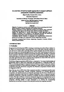
Figure 1. PRO3 functional architecture The functional model of figure 1 was derived based on the concept of classifying protocol processing functions into tasks that can be executed in a distributed manner on different functional entities. The on-chip peripherals of the protocol processor contain the following modules: Message Recognition, Generic Encoder/Decoder, Timer Pool, and Memory Management. Generally protocol processing is initiated by data reception from a network interface in the form of packet with specific protocol information residing in an appended header or trailer. Proper evaluation of the necessary fields that hold the protocol information leads to appropriate classification of the message. The Re-configurable Module handles the execution either of entire protocols or most frequently used and time-consuming branches of protocol FSMs in error free conditions, according to the requirements of each application, the type of the message or the protocol executed. The Re-configurable Module is accessible to the main RISC CPU through which configuration code is executed as well as protocol state information is
exchanged. The result of protocol processing in most cases is an update in stored protocol state, as well as the generation of a new or modified message/packet (a function to be executed by the Generic Encoder/Decoder) to be forwarded either to a higher layer protocol or to an output network interface. The symbolic feedback bus denotes potential return of messages in the input of the component in case that a multi-protocol stack is implemented. Certain priority rules can be applied along with specific access to/from the system. Implementation of timers, as well as efficient memory management including look-up table implementation, data and protocol context buffering are also an integral part of the protocol processing problem and potentially a bottleneck in generic architectures, which however can be offloaded to dedicated hardware units, as appearing in Figure 1. When programmability is set as a major requirement, RISC based micro-engines are best candidates for the implementation of functional units for many of the protocol processing functions. Following this approach we developed both fixed hardware units, as well as optimized micro-engines integrated with a commercial RISC processor in a layered architecture optimized for efficient protocol processing targeting link rates up to OC-48 (2,5 Gbit/sec). The actual block level PRO3 architecture is depicted in Figure 2. The PRO3 system is a distributed architecture incorporating dedicated hardwire modules for pre-processing and post-processing of low level protocols and two RISC-based Pipeline Modules (RPM) operating in parallel to facilitate load balancing, as well as the execution of protocols with different incoming and outgoing data flows. Packet pre-processing and lower layer protocol functions are executed by means of hardwired functionality (like the full ATM/CPCS layers), as well as programmable PDU processing and packet classification by means of a RISC-like micro-engine for Field Extraction and a controller of a high throughput external Ternary CAM (Content Addressable Memory) device for flexible and deterministic classification. CAM for classification
CAM I/F
CPU RAM
External Host CPU (optional)
Control RAM (state)
SDRAM I/F
CPU I/F
Control RAM I/F
RISC CPU
Timers
RPM
RPM
FEX PPE FMO
INSERT / EXTRACT
FEX PPE FMO
Internal BUS Pre-processing ATM/CPCS RX Layers CRC
IN
Post-processing Bus control, Internal Scheduling
Packet Classifier
ATM/CPCS TX Layers CRC
Data Memory Manager
OUT Traffic Scheduling
Pointer RAM
Storage DRAM
Scheduling RAM I/F Scheduling Memory
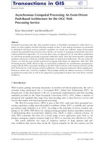
Figure 2. Block architecture of PRO3 system. Each RPM consists of a modified RISC core [3] surrounded by a Field Extraction (FEX) programmable microengine, which directly loads the required protocol data to the RISC for processing, and a Field Modification programmable engine (FMO in fig. 2) for flexible PDU construction and header modification. All together form a powerful 3-stage pipeline module capable of providing the mixed hardware and software processing heart of the system and performing the FSM of each protocol. The Internal Scheduling Unit, which is also a composite module, maintains a number of priority queues in order to schedule the forwarding of packets for processing according to the priority of each flow. It is also used to multiplex the execution of data transactions to the different internal destinations and/or allow for interleaved transactions over the Internal Bus. A dual scheduler module, configurable to operate either on fixed size cells or variable length packets, supports aggregate per group peak rate shaping for IP flows and guaranteed peak rate shaping per ATM flow. Other main blocks perform data/queue management and higher layer protocol processing (performed in SW on the on-chip standard Hyperstone RISC [3] or the external CPU). The common high speed path (up to the transport layer) is performed in the PRO3 hardware pipeline, and higher layer applications on the internal Hyperstone RISC CPU. Packets are stored per-flow in the external DRAM in queues implemented as linked list data structures [4] and can be retrieved by the Data Memory Manager module (DMM) in response to specific commands and be delivered over the internal bus either to the RPM modules or to the control RISC CPU or to a host CPU (via the insert/extract interface) or directly to the output interface. In general, the following sequence of operations is applied to each incoming packet: reception, classification, state processing, and transmission. Each of these generic functions consists of a set of lower level functions and can be understood as pipeline stages. In case of exception the packet is redirected to the internal or the external RISC CPU.
3. The RISC-based Pipelined Module, RPM The RISC-based Pipelined Module consists of three logical units: Field Extractor (FEX), the ProtocolProcessing Engine (PPE), which is a composite module, and Field Modifier (FMO). The PPE itself consists of three additional modules: the Modified Hyperstone RISC (MHY), the RPM-Glue Logic (RPG), and the Read/Write Control RAM module (RWR). Figure 3 depicts RPM top level design architecture.
This composite 3-stage design, where dedicated functional units are interconnect with a RISC core, offers an extreme advantage on tasks with high functional diversity. In this way, the usefulness and efficiency of a single processor core are extremely enhanced by providing the means to tailor its circuits for special tasks and reversely the diversity of applications of the dedicated units with their highly optimised configuration is broaden to accelerate protocol processing (or any computing task), yielding a clear cost/performance advantage. In a network processor, protocol portability is achieved accompanied with a high functional diversity of applications with significant performance improvement.
Figure 3.
RISC-based Pipelined Module
The Field Extraction/Modification Engines The Field Extraction and Field Modification engines of RPM module are pipelined and fully programmable modules that operate on a protocol-based firmware. Thus, only specific fields are extracted from FEX and fed to PPE module and these only specific fields are updated with their new values in FMO. This results in a constant ratio of cycle budget-to-packet length and optimal total processing time. The packets that are being received are stored in DMM and only the first 64 or 128 byte, containing the TCP/IP header information, called hereinafter segments, which needs to be processed are forwarded to RPM module. This efficient way of processing offers clear advantage of the architecture that differentiates it from other network processor designs.
The Modified Hyperstone RISC (MHY) The Modified Hyperstone RISC (MHY) module is the central protocol processing element in the PRO3 system. The MHY is a derivative of the standard Hyperstone E132XS microprocessor core [3]. Major architectural features of the MHY are: 1) The most recent stack frames are kept in a register stack, thereby reducing data memory accesses to a minimum by keeping almost all-local data in registers.
The Modified Hyperstone RISC uses 32 global and 64 local registers of 32 bits each, 16 global and 16 local registers directly addressable. Two sets of 14 global registers and 64 local registers are accessible from outside the core via a special port. Core accesses are switchable between the two sets of 14 global registers and between the two parts of a 32+32 register partitioning of the 64 local registers. In this way, state and packet information can be put into the register file by the RPM Glue Logic, and through the added read port, updated state and packet information is read out by the RPM Glue Logic. 2) 16 KByte dual-ported and fully static On-Chip Memory with the second port accessible from outside the core. Through the added port, initialization and status repots are obtained from an external/internal CPU. Additionally pipelined memory access allows overlapping of memory accesses with execution. 3) On-chip Instruction Cache omits instruction fetch in inner loops and provides pre-fetch. 4) Variable-length instructions of 16, 32 or 48 bits provide a large, powerful instruction set, thereby reducing the number of instructions to be executed. Primarily used 16-bit instructions halve the memory bandwidth required for instruction fetch in comparison to conventional RISC architectures with fixed-length 32-bit instructions, yielding also even better code economy than conventional CISC architectures. Most instructions are executed in one cycle and are orthogonally set. An instruction pipeline depth of just two stages — decode/execute — provides branching without insertion of wait cycles in combination with Delayed Branch instructions.
The RPM-Glue Logic (RPG) The RPM-Glue Logic (RPG) interfaces and transfers data between the Field Extractor, the Field Modifier, the Modified Hyperstone RISC and the Read/Write Control RAM module. The main features of RPM-Glue Logic are: 1) Programmable entry points for SW packet handling according to protocol type and message type 2) Programmable handling of “input” and “output” parts of flow state 3) Implements bypassing of updated flow state for backto-back processing of packets of the same flow 4) Full bandwidth input/output capacity The operation of RPG for incoming packets includes transferring of packet fields from the Field Extractor to the local portion of the registers of the modified Hyperstone core, and initiating packet processing when the modified Hyperstone core has completed processing
of the previous packet. Additionally, RPG reads and updates flow state information from and to the Read/Write Control RAM and forward it to the MHY core. It is worth noting that the MHY core does not have direct access to the external memory and application firmware is resident on its on-chip cache memory. Respectively for outgoing packets RPG interprets the outcome of the packet processing and transfers the updated packet fields from the local portion of the registers of the modified Hyperstone core to the Field Modifier. Additionally, RPM Glue Logic has to maintain consistency between the flow state information used in the packet processing, by means of bypassing. When packets of the same flow are processed back-to-back, the state flow read from the Control RAM is stale, and the RPG undertakes the responsibility to forward internally the correct flow state information, and implement the necessary control and status registers for the operation of the PPE, and perform reset and support the initialisation sequences for PPE. To process a packet the RPM Glue Logic places the extracted fields obtained from the Field Extraction engine as well as the state information about the flow into the MHY register file and/or internal memory. When this is complete, dedicated signals are used to indicate the correct packet data locations and dispatch tables to point to the appropriate processing routine. While the process is running, the RPM Glue Logic may use the second part of the register file to already load the field and state information for the next packet.
4. The Scheduler Unit Scheduling in such a processor environment is required to resolve contention for processing resources in a fair manner, or to distribute in time the transmission of packets/cells (in a network medium) due to traffic management rules (shaping). It is evident that packets from connections with low delay requirements (i.e. realtime, high priority traffic) should bypass the FIFO service discipline and be forwarded for internal processing with higher priority. When the processor cannot sustain worstcase conditions under line rates such as 2.5Gbps or 10Gbps, as is the case for TCP stateful inspection, queuing is necessary and an appropriate queuing service discipline has to be implemented. Therefore the scheduler unit must maintain a number of priority queues in order to schedule the forwarding of packets for processing according to a configurable priority per flow or per QoS class. The scheduling unit in the PRO3 system consists of a Task Scheduler Unit, TSC, which controls the data flow in the high-speed internal bus and a Traffic Scheduler Unit, TRS, to shape the generated
traffic according to traffic management specifications and service level agreements. Each flow is served by the DMM through a dedicated queue (in which the data/packets are stored/reassembled) directly indexed by the flowID value, assigned by the Classifier, uniquely identifying the protocol data and context for each connection and each layer of the protocol stack. The DMM is responsible to temporarily buffer incoming data packets, until they are fully processed and ready to be forwarded (or discarded). It implements queues of packets, one queue per active connection, and each packet being of variable length. The DMM segments the incoming packets into fixed-size segments of 64 bytes. This segmentation of memory space allows optimizing the memory utilization, increasing the performance of the DMM, and reducing the delay of high-priority packets [4]. The queues that are managed by the DMM will be called Data Queues in order to distinguish them from the TSC and TRS data structures and are associated explicitly with one destination within PRO3 and a specific handler/protocol that will be used for the processing of each packet classified in that queue. The data structures managed by the TSC and TRS will be called hereafter Scheduling Queues (and will be denoted as SIDQ). The organization of the SIDQs will be discussed in detailed in the next sections.
Task Scheduler module, TSC In total, there are 32 scheduling queues that may be used for sharing the processing resources of system. (i.e. field extraction & classification module, RPMs, RISC & external CPU) in a Weighted Round Robin manner [6]. Each of these queues is associated with one of the possible internal destinations of packets within PRO3 and a specific handler protocol that will be executed for the data of this flow. Obviously more than one data queues will share the same scheduling queue. The multiplexing of multiple flows in one scheduling queue (flow group) is based on the Round-Robin (RR) discipline. Thus, all the flows that hash into the same scheduling queue will share equally among them the portion of internal processing resources (in terms of service opportunities) that is allocated according to the pre-configured weight for that scheduling queue. The 32 scheduling queues are hierarchically organized. The first queue shall be treated with strictly highest priority over the others (with most prominent use to schedule traffic with low delay requirements for processing by the RPMs). The remaining 31 scheduling queues can either be treated with the same priority level and be serviced in a Weighted Round Robin (WRR)
fashion or (determined upon configuration) can be hierarchically organized into two sets of 15 and 16 queues respectively with strict priority of the first set of queues over the second. Scheduling queues of the same priority/set are serviced in a WRR fashion.
Traffic Scheduler module, TRS The outgoing Traffic Scheduler (TRS) orders the cells (ATM) or packets (IP) to be transmitted to the output network interface performing a shaping function in terms of peak-rate policing. Whenever the output data queues are active the TRS sends commands for transmission respecting the minimum transmission interval for flows that are amendable to specific traffic contracts and service level agreements. The TRS can support these functions utilizing the same basic data-structures required for the operation of the TSC and the same external memory space. Similarly to the TSC case the flows are grouped into 32 queues (SIDQs) on the basis of their predefined peak rate transmission. The 32 basic rates are adequate even in very high-speed link rates [7]. All the flows in the same SIDQ are shaped in the same peak rate (measured in segments or cells per slot). The flows within a SIDQ are served in a round robin way and the cell/packet transmission interval is dynamically modified as a function of the number of flows with pending packets existing in the rate queue. TRS operation is based on the NTT, MTI and AC parameters, denoting the Next Transmission Time, Minimum Transmission Interval and number of Active Connections respectively. The NTT variables are implemented as countdown timers kept on chip, one per scheduling (rate) queue, enabled by the general Slot Clock. In ATM based applications AAL packets leave the system cell by cell. Each time that a cell from the rate queue i is transmitted the timer is set to the MTIi/ACi value (since MTI represent the basic rate for a single flow). In IP applications, the NTTi is associated with the transmission of a data segment whose size is predefined. Each time that an IP packet is waiting to be transmitted, the timer is set to the value Ti*(PL/PDS), where PL is the packet length and PDS the size of the predefined data segment. Thus, 32 discrete rates are supported with guaranteed peak rate shaping per ATM flow and aggregate per group peak rate shaping for IP flows. When a counter reaches zero, a flag rises indicating that a cell should be transmitted and the timer is reset. To achieve maximum throughput in the worst case, 32 flags should be inspected in a slot time and this yields for the same straightforward implementation of a priority enforcer as in the case of circular scan of eligible SIDQs by the TSC circuitry.
5. Performance Evaluation In this last section we will quantify the performance enhancements that the innovative architecture of the PRO3 protocol processor can achieve. Our approach combine legacy benchmarking metrics for estimating the performance of programmable micro-engines (Instructions/Sec-IPS, Instructions/Cycle-IPC, etc.) as well as the trends of the NP Forum (NPF) [8]. A new metric introduced by the NOF is the Headroom Concept, which has been introduced in order to allow the measurement of the ability of a Network Processing Platform to perform multiple networking functions aggregately, in any combinations that make sense for networking applications and still maintain wire-speed performance. We must note here that since PRO3 follows a hybrid architecture with fixed H/W units and programmable engines designed to operate either in pipeline or in parallel we will denote Headroom as the percentage of the available processing resources of the chip that can be exploited in parallel. The main processing units that can operate in parallel are the two RPM units and the central RISC unit. RPM throughput is determined by the worst-case performance of each of its pipeline stages and results are discussed in detail in the sequence. Of course when wire-speed operation is achieved then the performance is limited by the nominal speed of operation of the interfaces of the chip. 2,5 Gbps sustained throughput can be achieved for average case conditions according to typical IP packet distributions. Worst-case conditions (i.e. continuous stream of minimum size 40-Byte IP packets) deteriorate this performance according to the analysis that follows in this section. The performance evaluation has been based on the following facts: the PRO3 chip is implemented using UMC 0.18 CMOS technology and the clock speed is 200MHz with a 64-bit wide internal bus. For the performance evaluation of the programmable units firmware for all the microengines was developed and open source C code was ported for implementing a stateful inspection Firewall with Network Address Translation (NAT) support [5]. Samples of real TCP/IP traffic have been used as input in H/W simulation and the processing time in each module was measured. In order to evaluate the application performance, simulations with different packet and header lengths were carried out. Based on the results optimisation of the cores design was possible. Following the performance of the cores of the RPM module is investigated. Two parameters were measured, the total number of the executed instructions and the corresponding processing time. Based on these
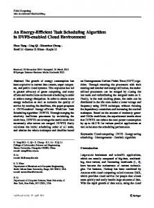
figures, the throughput of each sub-block and of the whole module was estimated. Figure 4a displays the total number of instructions executed by FEX block in the case of 64-byte and 128byte packet. For the particular implementation of the stateful-inspection Firewall application, FEX sub-block is commissioned to process only the TCP and IP header of each packet, by extracting the fields mentioned in Table A. The Data Memory Manager sends to RPM either one segment, in case the IP packet length is no more than 64bytes, or two segments (each 64-bytes) in case the IP packet is larger than 64 bytes. In this manner, it is guaranteed that all the relevant fields from IP and TCP headers will be fetched for processing to the FEX block of the RPM. Form figure 4a, it is worth noting that the number of required instructions is independent of the IP packet length. In addition it may be observed that for small IP packets (IP packet length between 40 and 64 bytes) the number of required instructions is proportional to the IP header length, which depends on the number of valid IP options. Additionally, for IP packets that are larger than 64 bytes, a fixed number of instructions are required for the cases where the IP header length is between 20 and 48 bytes, while for the rest of the IP header length cases, this number increases proportionally to the IP header length, reaching a maximum of 43 instructions in case of an IP-packet with 60 byte of IP options.
Figure 4. (a) Number of executed instructions and (b) processing time of FEX micro-engine versus IP header lengths The average cycle-to-instruction ratio for the FEX micro engine is 1.6. Although this value can be improved by reducing the most clock-consuming instructions, however since the processing does not depend on the total IP packet length, no major improvement is anticipated. Finally, from Figure 4a it can be seen that the total number of instructions for two segments (IP packet length larger that 64 bytes) is smaller than that for one segment (IP packet length between 40 and 64 bytes). This is due to the fact that the firmware easily identifies the case of two segments and, based on the IP header lengths (resides in first segment), scans faster and jumps directly to the fields to be extracted, which reside in the second segment. The corresponding processing time of FEX micro-engine is displayed in Figure 4b. From this
figure it can be seen that the cycle budget of the FEX micro-engine for 40-byte packets is close to 4 Mpackets/sec (Mpps). This throughput can be doubled when the traffic is balanced between the two RPM modules and sustain in this way OC-48 rate even for TCP/IP traffic of 40-byte packet length. Filed Modifier also receives the same number of segments as FEX –one or two 64-byte segments– depending on the total packet size –, which are stored in the bypass FIFO. However in Field Modifier, the total process time, depends on the IP header length and the number of valid bytes that reside within the segments (one or two) stored in the bypass FIFO. To this end, optimization was possible yielding significant improve in FMO sub-block performance. For example, the average cycle-to-instruction ratio was 2.2 and after the optimization was decreased down to 1.7. That was attainable after detecting, which firmware routines are most often called, which are the most clock-consuming ones and which can be executed in parallel. After the optimization, a significant decrease in the number of executed instructions was achieved, almost 60%, resulting in shorter processing times and in an improved of the instruction-to-clock ratio. Figure 5 displays the total number of the executed instructions of the optimized Field Modifier versus the total IP packet length for different IP header lengths. From Figure 6 we may observe that for packets having the same IP header length (same number of valid IP option) the total number of FMO instructions required for NAT is, as expected, proportional to the IP packet length. Additionally, for IP packets that have the same length the number of instructions is inverse proportional to the IP header length (number of valid IP options). This is due to the fact that, when more IP options are present the less jump instructions the micro-engine needs to scan the contents of the packet.
Figure 5. Number of executed instructions in Field Modifier for different packet/header lengths Finally, Figure 6 displays the total processing time versus the IP segment length. From Figure 6 it can be derived that a single Field Modifier module can sustain about 4 Mpps traffic assuming packets of 40-byte. When both the RPM modules are used then the throughput is double to 8 Mpps, which exceeds the maximum 7.5Mpps for 40-byte packets for OC-48 line rate.
Figure 6. FMO Processing time versus packet length for different IP header lengths Concerning the third complex sub-block of RPM module, the Modified Hyperstone RISC, its throughput depends heavily on the custom running application and it is estimated, that for complex applications, like TCP state updating, less than 170 instructions are needed and this of course has an impact in the overall throughput. However, for complex scenarios this is a trade off that any network processor faces. Based on our analysis, by using two RPM modules and balancing the load between them (supported by the Internal Scheduler design) 4 Mpps can be sustained at worst case, with only TCP traffic. For the average IP packet (about 128 bytes) this rate exceeds the OC-48 rate of 2,5 Gbps. It is worth noting that packet classification, queuing and scheduling can support 2,5Gbps link rates even for worst case minimum packets.
6. Conclusions In this paper the Programmable Protocol Processor architecture was presented with emphasis in the acceleration of packet processing using an innovative concept of a 3-staged pipelined processing operation and certain scheduling implementation in order to balance workload and resolve internal contention. Such a design is suitable for protocol processing in high-speed networks. The PRO3 chip is being fabricated in UMC’s 0.18 µm logic process occupying about 52mm2 of area and will be packaged in a 1096 BGA package. Samples are expected later this year. This work was performed in the framework of the PRO3 project, which is partially funded by the IST Program of the European Community. The authors would like to acknowledge the contributions of their colleagues from Lucent Technologies, Hyperstone AG, IMEC, National Technical University of Athens, Ellemedia Technologies, Technical University of Crete and InAccess Networks.
7. References
[1] T. Wolf, J. Turner, “Design Issues for high-performance Active Routers”, IEEE Journal on Selected Areas in Communications, Vol. 19, pp. 404-409, March 2001. [2] G. Konstantoulakis, et al. “A Novel Architecture for Efficient Protocol Processing in High Speed Communication Environments”, in proc. of ECUMN’2000, Colmar, France, October 2000. [3] Hyperstone AG, E1-32X RISC/DSP, http://www.hyperstone.com. [4] A. Nikologiannis, M. Katevenis, “Efficient Per-Flow Queueing in DRAM at OC-192 Line Rate using Out-of-Order Execution Techniques”, in proc. of ICC2001, Helsinki, Finland, June 2001. [5] N. Nikolaou, J. Sanchez, T. Orphanoudakis, D. Polatos N. Zervos, “Application Decomposition for High-Speed Network Processing Platforms”, 2nd European Conference on Universal Multiservice Networks, ECUMN’2002 April 2002, Colmar France. [6] M. Katevenis, S. Sidiropoulos, C. Courcoubetis, “Weighted Round Robin Cell multiplexing in a general-purpose ATM switch chip”, IEEE Journal on Selected Areas in Communications, Vol. 9, No 8, October 1991. [7] M. Shreedhar, G. Varghese, “Efficient Fair Queuing using Deficit Round Robin”, IEEE Transactions on Networking, Vol.4, No 3, June 1996. [8] P.R. Chandra and S.Y. Lim, “Framework for Benchmarking Network Processors, Draft 1.0, Network Processing Forum, August 2002.