Mar 12, 2006 - tion and realizes a customized processor capturing the ... (a) A high-level application to a hardware/software system generation (b) Processor ...
Processor Customization on a Xilinx Multimedia Board Partha Biswas, Sudarshan Banerjee, and Nikil Dutt,
CECS Technical Report #06-04 Center for Embedded Computer Systems School of Information and Computer Science University of California, Irvine, CA 92697, USA Mar 12, 2006
Abstract Performance of applications can be boosted by executing application-specific Instruction Set Extensions (ISEs) on a specialized hardware coupled with a processor core. Many commercially available customizable processors have communication overheads in their interface with the specialized hardware. However, existing ISE generation approaches have not considered customizable processors that have communication overheads at their interface. Furthermore, they have not characterized the energy benefits of such ISEs. This report presents a soft-processor customization framework that takes an input ‘C’ application and realizes a customized processor capturing the microarchitectural details of its interface with the specialized unit. The speedup, energy, power and code size benefits of the ISE approach were accurately evaluated on a real system implementation by applying the design flow to a popular Xilinx Microblaze soft-processor core synthesized for four real-life applications. It was found that only one large ISE per application is sufficient to get an average 1.41× speedup over pure software execution in spite of incurring communication overheads. Finally, a simultaneous savings in energy (up to 40%) and power (up to 12% peak power reduction) with this increased performance were observed.
1
Contents 1
Introduction
4
2
Customized Processor Model
5
3
Related Work
5
4
Framework for Complete System Realization 4.1 Preprocessing Input Application . . . . . 4.2 ISE Generation Phase . . . . . . . . . . . 4.3 H/W Generation Phase . . . . . . . . . . 4.4 S/W Generation Phase . . . . . . . . . . 4.5 Processor Subsystem Generation Phase .
. . . . .
. . . . .
. . . . .
. . . . .
. . . . .
. . . . .
. . . . .
. . . . .
. . . . .
. . . . .
. . . . .
. . . . .
. . . . .
. . . . .
. . . . .
. . . . .
. . . . .
. . . . .
. . . . .
. . . . .
. . . . .
. . . . .
. . . . .
. . . . .
. . . . .
. . . . .
6 7 7 7 8 10
5
Communication Template for Xilinx Microblaze
11
6
Experiments 12 6.1 Experimental Setup . . . . . . . . . . . . . . . . . . . . . . . . . . . . . . . . . . . . . . 12 6.2 System Implementation on the Board . . . . . . . . . . . . . . . . . . . . . . . . . . . . . 13
7
Experimental Results 13 7.1 Performance and Code Size . . . . . . . . . . . . . . . . . . . . . . . . . . . . . . . . . . 13 7.2 Power and Energy Results . . . . . . . . . . . . . . . . . . . . . . . . . . . . . . . . . . 15 7.3 Slices Utilization . . . . . . . . . . . . . . . . . . . . . . . . . . . . . . . . . . . . . . . 16
8
Summary and Future Directions
16
A System Realization on Xilinx Multimedia Board
18
B Steps for System Simulation using ModelSim
21
C Creating a Custom FSL Interface
26
D VHDL Source for the Communication Template
26
E Structural AFU model for adpcm-d
29
F AFU with its Interface for adpcm-d
36
List of Figures 1 2 3
Target Customized Processor Subsystem . . . . . . . . . . . . . . . . . . . . . . . . . . The Flow of our Framework . . . . . . . . . . . . . . . . . . . . . . . . . . . . . . . . . (a) A high-level application to a hardware/software system generation (b) Processor subsystem generation . . . . . . . . . . . . . . . . . . . . . . . . . . . . . . . . . . . . . . .
5 6 8
4
5 6 7 8 9 10
The ISE here is composed of the shaded instruction nodes. (a) An example showing the LastDef point and the FirstUse point; (b1) an example where it is not possible to insert the ISE under consideration; (b2) After code restructuring; (b3) positioning of the ISE between LastDef and FirstUse. . . . . . . . . . . . . . . . . . . . . . . . . . . . . . . . Measuring System Power . . . . . . . . . . . . . . . . . . . . . . . . . . . . . . . . . A DP-external AFU Interface . . . . . . . . . . . . . . . . . . . . . . . . . . . . . . . Microblaze Processor Core with an AFU and its Interface. . . . . . . . . . . . . . . . . Communication Template for AFU Interface in Microblaze . . . . . . . . . . . . . . . . Xilinx Multimedia Board . . . . . . . . . . . . . . . . . . . . . . . . . . . . . . . . . . An ISE for ADPCM ENCODER (adpcm-e) having 4 inputs and 2 outputs; each operation node maps to a hardware component. . . . . . . . . . . . . . . . . . . . . . . . . . . .
. . . . . .
9 10 10 11 12 13
. 15
1
Introduction
Typically, applications running on a programmable platform can be executed either as a software algorithm or on a specialized hardware unit. The software approach is the slowest but most flexible while the hardware approach is the fastest but least flexible. Instruction Set(IS)-extensible processors comprise an emerging class of processors (especially in the embedded domain) that permit execution of only the critical application kernels in customized units (as hardware) with the rest of the application executing on the processor core (as software). This speeds up the application without compromising the processor clock or modifying the architectural model of the processor and yet preserves the flexibility of the software approach. We call such a coprocessing hardware element an Ad-hoc Functional Unit (AFU). The AFU operation is triggered by an instruction or a set of instructions that we call an Instruction Set Extension or ISE. In the past, researchers have modeled AFUs having no communication overhead. However, many commercially popular customizable processors have communication overheads in their interface with AFUs. Therefore, our goal is to consider the microarchitectural details of an AFU interface in a processor customization framework and accurately evaluate the performance and energy benefits of ISEs in a realistic processor. The efficacy of the framework lies in seamlessly considering the synchronization between the processor and the AFU in a unified manner for different applications. Minimizing power and energy consumption is as important as maximizing performance in embedded systems. A high power consumption may destroy a chip completely through overheating while a high energy consumption may reduce the battery life of an embedded device. Therefore, even though ISEs can achieve high speedups, designers need to determine if this speedup comes at a price of increased power. This report shows that increased performance can also reduce both power and energy of a customizable processor in the presence of an AFU and reports the effects on code size and area. It is predicted [17] that by 2010, over one-third of all PLD/FPGA devices are expected to have microprocessor cores, up from 15% today. Xilinx Microblaze [10] is a popular commercially-available soft-core. We demonstrate the use of our framework by transforming a given input application into a running Xilinx Microblaze hardware-software system. For four real-life applications (from Mediabench and EEMBC suites), we measure the real performance gain over pure software execution and also accurately evaluate energy and power consumption. Our experimental results show that significant speedup is obtained only when an ISE contains a large set of atomic operations. With only one large ISE per application, we obtained speedup of up to 1.47× over simple software execution and simultaneously up to 40% energy saving and 12% peak power reduction. To the best of our knowledge, this is also the first attempt to present the details of interfacing an AFU with a customizable soft-core. The main contributions highlighted in this report are the following: • We present a generalized interface-aware soft-processor customization framework for mapping an application in C into a running processor-AFU subsystem that enables accurate evaluation of all the metrics deemed important in embedded system design, namely, performance, energy, power, cost and code size. • By applying our framework to Microblaze soft-processor core, we conclude that ISEs can be simultaneously beneficial in terms of performance, energy, power and code size. The rest of the report is organized as follows. We present our target customizable processor model in Section 2. In Section 3, we present some related research work. We describe our framework for transforming a given application to a customized processor subsystem in Section ??. Section 6.1 presents
Processor Subsystem
Program Memory
Core
DP−external
Register File
Data Memory
Bus External
Tightly−coupled
Execution Unit
AFU
AFU
External
DP−internal
Interface
Tightly−coupled
Peripherals Interface
Decoder
AFU
Coprocessor Loosely−coupled External Memory
Figure 1. Target Customized Processor Subsystem
how we use the framework to target Xilinx Microblaze soft-processor core. In Section ??, we describe our experimental results. Finally, Section 8 concludes the report.
2
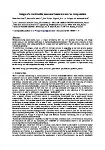
Customized Processor Model
Our goal is to map a given application to the target customizable processor model shown in Figure 1. In this model, the software part of the application stored in the program memory is composed of base instructions to be run on Execution Unit and ISEs to be run on the hardware part, i.e., AFUs. An AFU can be tightly-coupled with the core through an AFU interface inside the processor subsystem or loosely-coupled through an external bus. The AFU interface or the external interface implements the communication protocol between the AFU and the processor and thus controls synchronization of data and access to the processor register file. The function of an ISE is to transfer control to an AFU for execution. An ISE can be either a single user-defined instruction or a set of multiple pre-defined instructions. A single user-defined instruction is decoded as a special instruction, which encapsulates inputs and outputs of an AFU as source and destination operands respectively. The decoder takes the responsibility of issuing such a special instruction to an appropriate AFU for execution. Alternatively, sending inputs and receiving outputs of the AFU from the processor can be done at the expense of multiple data transfer instructions. Such instructions must already exist in the instruction set of the processor in the form of “send data to AFU” and “receive data from AFU” instructions. In this case, the AFU incurs communication overhead at its interface while sending and receiving data.
3
Related Work
Several algorithms [1, 4, 2, 3, 5, 6] have recently been proposed to identify ISEs in a given application. The speedups over simple software execution claimed in most of the approaches [1, 4, 2, 3] are estimated by assuming a typical RISC processor execution model. The methodology in [5] targets Trimaran research infrastructure. Using a simulator, the authors show speedup for applications that reuse AFUs generated for other applications in the same domain. Such reuse of AFUs across application is possible only when ISEs found were reasonably small in size. However, we will confirm in our experimental results that such
small-sized ISEs would not generate a considerable speedup for AFUs with communication overheads. Sun et al. [6] employs a Tensilica Instruction Extension (TIE) compiler in their methodology and operates at a higher (C source-code) level of abstraction. Therefore, this methodology relies more on designer’s experience for ISE identification and mapping to AFUs. The AFU in this case therefore does not have any communication overhead. Fei et al. [7] integrated a fairly accurate energy estimation engine in the same framework, but they do not report a comparison of energy before and after extending the processor. A recent work having a goal of real system implementation [8] generated application-specific instructions for Altera Nios II processor in the presence of AFUs that do not have communication overheads. The results show a good speedup and limited area overhead, but they do not discuss energy or power consumption. Unlike [8], in this report, we deal with the non-trivial details of synchronization between the processor and the AFU with the help of a generic communication template. Note that in the prior related work, the AFU in general did not have communication overheads at its interface. Indeed, there are many commercially available processors providing such an interface. Common examples are Altera Nios II processor [13], LEON processor [12], etc. However, there are similarly many commercial customizable processors where AFUs incur overhead in sending and retrieving data. Some examples include STMicroelectronics ST120 [11], Xilinx Microblaze processor [10], etc. To the best of our knowledge, ISE generation in the context of AFUs incurring communication overheads at their interface with the core processor has not been studied yet. This is our motivation for proposing a framework that is capable of incorporating different AFU models and in particular, targeting Xilinx Microblaze soft-core. We apply the design flow of our framework to study performance gain, energy/power consumption, code size reduction and area overhead with the introduction of an AFU into the Microblaze subsystem.
4
Framework for Complete System Realization
Our framework takes as input a high-level application (in C), and generates an executable and an AFU with appropriate interfacing protocol (as shown in Figure 2). The executable runs in the processor core as software containing ISEs for invoking the AFU operation in hardware. Our target for running the complete processor-AFU subsystem is an FPGA platform. Application ISE Generation ISEs Latency
S/W Generation
H/W Generation
Interface
Executable
System
Processor Core
AFU+Interface
AFU FPGA platform
Figure 2. The Flow of our Framework
The expanded view of our framework is shown in Figure 3(a). It has five main phases: Preprocessing phase, ISE generation phase, S/W generation phase, H/W generation phase, and Processor subsystem
generation phase. The Preprocessing phase takes the input application and generates an annotated intermediate representation. The ISE generation phase generates ISEs under microarchitectural constraints. The H/W generation phase synthesizes the corresponding AFUs with their interfaces and the S/W generation phase generates the executable. A dotted arrow between the two phases indicates that the latency of an ISE obtained in the H/W generation phase is passed on to the S/W generation phase. Finally, the Processor subsystem generation phase builds the complete running system for evaluation. 4.1
Preprocessing Input Application
This phase can be identified as a box labeled “Preprocessing” in Figure 3(a). A compiler front-end yields Control Flow Graph (CFG) and Data Flow Graph(DFG) of an input application and runs predication to combine a set of small basic blocks into a large basic block. The input application is then profiled and the basic blocks are annotated with their execution counts. A component library is created containing a synthesizable combinational element corresponding to each instruction in the target instruction set. Each element in the library is synthesized for a given technology and the corresponding instruction in the DFG is annotated with a normalized hardware latency. Each instruction in the DFG is also annotated with its software latency obtained from the target architecture specification. 4.2
ISE Generation Phase
This phase (shown as the “ISE generation” box in Figure 3(a)) is integrated with the compiler frontend. An ISE generation algorithm takes the annotated CFG/DFG and returns subgraphs or ISEs that would maximize performance under microarchitectural constraints. Although any ISE generation algorithm can be used, we use ISEGEN in our framework because it identifies all the instances of an ISE exploiting large-scale ISE reuse. 4.3
H/W Generation Phase
We show this phase in a box marked “H/W generation” in Figure 3(a). The two subtasks of this phase are component library binding and interface synthesis. The identified subgraph or ISE is isolated and each instruction in the subgraph is replaced by the corresponding element in the component library. Figure 10 shows an example subgraph where each node maps to an element in the component library. The data dependencies between the instructions are replaced by port-to-port connections between the elements and the resulting structure is an AFU. This structural AFU model is then synthesized to evaluate the critical path length. The critical path length divided by the clock period of the processor core gives the number of cycles needed for the AFU operation. This latency information is passed on to the scheduler in the S/W generation phase (shown with a dotted arrow in Figure 3). The evaluated number of cycles is also used to synchronize the AFU with respect to the core. Apart from the component library, the designer also creates a communication template for AFUs, which captures the communication protocol between the processor core and the AFU. The writing back of result from the AFU to the processor is delayed by the exact number of cycles required by the AFU operation. The implementation of communication protocol together with synchronization with the core completes the AFU interface synthesis. Note that the H/W generation phase can be applied to synthesize the AFU and its interface in the customized processor model presented in Figure 1.
Application
Preprocessing Compiler Front-end
Profile code
CFG/DFG
Annotate w/ hw/sw latencies, exec count
S/W generation
ISE generation
Replace subgraph by ISE
Component Library
Constraints
Communication Template
Annotated CFG/DFG
CFG/DFG w/ ISEs
ISEGEN
Scheduling Register Alloc ISEs or subgraphs
Compiler Back-end
H/W generation Component Library Binding Replace ops by components and edges by cnxns
Executable
Clock Period
Interface Synthesis
Structural AFU model Eval Crit. Path Calc # Cycles
Couple Computation w/ Communication
AFU + Interface
# Cycles
Latency
(a)
AFU + Interface
Processor model Synthesis P/R
Processor Subsystem generation
System
(b) Figure 3. (a) A high-level application to a hardware/software system generation (b) Processor subsystem generation
4.4
S/W Generation Phase
This phase (shown in Figure 3(a) as a box titled “S/W generation”) generates code for the target processor taking into account the presence of AFUs. The two subtasks in the S/W generation phase are
subgraph matching and subgraph replacement with ISEs. Since all possible instances of an ISE have already been enumerated by the ISE generation phase, the subgraph matching simply consists of a DFG traversal and marking constituent instructions of the ISE in the DFG.
1
LastDef
2 3
FirstUse
1
1
3
2
FirstUse
3
LastDef
1
3
LastDef
2
FirstUse
4
4
4
4
2
5
5
5
5
(a)
(b1)
(b2)
(b3)
Figure 4. The ISE here is composed of the shaded instruction nodes. (a) An example showing the LastDef point and the FirstUse point; (b1) an example where it is not possible to insert the ISE under consideration; (b2) After code restructuring; (b3) positioning of the ISE between LastDef and FirstUse.
After subgraph matching, the ISE is used to replace the set of marked instructions in the DFG. We depict the ISE replacement strategy in Figure 4. An ISE can be placed anywhere between the point where its source operands have their last definition (LastDef) and the point where its destination operand has its first use (FirstUse) as shown in Figure 4(a) (the shaded nodes identify the ISE under consideration). Since ISE generation phase has ensured convexity of the identified subgraphs, it is never possible to have a dependency edge from the FirstUse node to the LastDef node because this would make the subgraph non-convex. Consequently, it is possible to encounter a situation where a FirstUse point precedes a LastDef point in the instruction sequence. This renders the subgraph replacement impossible without code restructuring. Consider the following sequence of operations in instruction order: (1)a = b ∗ c; (2)f = a|0x2; (3)e = 5; (4)d = a + e; (5)g = e − d. Suppose the ISE under consideration is a multiply followed by an add, as identified by the nodes labeled 1 and 4 in Figure 4(b1) respectively. Figure 4(b1-b3) show an example of how the placement of ISE between LastDef and FirstUse is accomplished through code restructuring. Since in this case the FirstUse point appears earlier in the instruction chain than the LastDef point, the ISE cannot be placed anywhere (Figure 4(b1)). So, instruction reordering has to be done in order that the LastDef point precedes the FirstUse point. This reordering is possible because there is no dependency from FirstUse to LastDef. Figure 4(b2) shows the code snippet after restructuring Figure 4(b1) (i.e., swapping the positions of node 2 and node 3) and Figure 4(b3) shows the placement of ISE between the LastDef point (node 3) and the FirstUse point (node 2). If an ISE is used as a single user-defined instruction, a single instruction just replaces the set of constituent instructions. Replacing the multiply and the add with a single user-defined instruction (ISE1(·, ·, ·)), the resulting instruction sequence (as in Figure 4(b3)) would become: (3) e = 5; (1),(4) d = ISE1(b, c, e); (2) f = a|0x2; (5) g = e − d. However, if an ISE is represented as a set of predefined data transfer instructions (send(·), receive(·)), the resulting instruction sequence after ISE replacement would appear as: (3) e = 5; (1),(4) send(b); send(c); send(e); receive(d); (2) f = a|0x2; (5) g = e − d. After subgraph replacement with ISE, the compiler performs scheduling, register allocation and target code generation as a back-end pass. Note that the latency of the ISE required by the scheduler is derived
Executable
Memory Image
System
Superimpose
Structural Model
Timing Info
Hardware Simulation
Routing Info Power Simulation
VCD
Power Report
Figure 5. Measuring System Power
from the H/W generation phase as shown in Figure 3(a).
4.5
Processor Subsystem Generation Phase
We show this phase in Figure 3(b). As a final step, the processor model of the target Soft-core along with the AFU and its interface are synthesized and implemented using standard synthesis and Placeand-Route tools. The executable generated in Figure 3(a) and the system synthesized in Figure 3(b) are deployed in two schemes, one for measuring speedup and the other for evaluating energy/power consumption. With the goal of measuring actual time spent in running the application, the scheme for Performance Measurement uses the bitmap of the synthesized system to program an FPGA fabric, which then becomes the platform for actually running the executable. The executable is downloaded into the system memory through a JTAG port and the number of cycles for running the executable is measured using a hardware timer. Program Memory
Processor Subsystem Core
Tightly−coupled
Register File
Data Memory
Bus
Interface
Execution Unit
External
AFU
External
DP−external
AFU
Interface
Decoder Peripherals
External Memory
Figure 6. A DP-external AFU Interface
Since there is no direct way to measure power of a running system on the FPGA fabric, we employ a different scheme for Power/Energy Evaluation (depicted in Figure 5) for accurately evaluating the power and energy consumption of the system. Note that there are three kinds of information in the post-
Place-and-Route system (Figure 3(b)): the structural model of the system, the timing information and the routing information. We superimpose the memory image of the executable (in Figure 3(a)) into the memory section of the structural model. This complete structural model along with the timing information is run through a cycle-accurate hardware simulator to generate a Value Change Dump (VCD) of all the signals in the structural netlist. The routing information and the VCD information together are then used by a power simulator to generate the dynamic power consumed at different time steps. We then derive the total energy dissipated in the system from the reported power and the measured execution time. Now, we apply our processor customization framework to generate a real system.
5
Communication Template for Xilinx Microblaze
Xilinx Microblaze [10] is a soft-core with a DP-external AFU interface (as shown in Figure 6). We demonstrate the utility of our framework by transforming a given input application into a running Microblaze hardware-software system. Microblaze has a DP-external AFU to be connected with the processor via Fast Simplex Links (or FSLs). FSLs are dedicated point-to-point unidirectional 32-bit wide FIFO interfaces. The Microblaze is capable of including a maximum of 8 input and 8 output FSLs. Counter Count
Microblaze Processor
FSL 8X8
Cnt_en
AFU Int.
AFU_en In
AFU
Out
CLK Figure 7. Microblaze Processor Core with an AFU and its Interface.
Microblaze is a 32-bit RISC processor with a simple 3-stage pipeline. Figure 7 shows an AFU and its interfacing with the Microblaze processor core via 8 × 8 FSL channels. The AFU interface implements the processor-AFU communication protocol and is synchronous with the Microblaze processor through a global clock (CLK). The AFU interface is also connected to a counter module to enable counting whenever required. If the count enable signal (Cnt en) is ‘1’, counting is enabled. Otherwise, the counter is reset to ‘0’. The signals In[32] and Out[32] are used to send data to and receive data from the AFU respectively. When the AFU-enable signal, AFU en is ‘1’, the AFU latches the output in Out[32]. In Figure 8, we present the generic communication template for Microblaze-AFU interaction as a Finite State Machine (FSM) synchronous with respect to CLK. For the sake of explanation, we call an FSL channel FSL R when it is used for AFU read operation or FSL W when it is used for AFU write operation. Associated with every FSL R channel is a set of three signals, namely, (FSL READ SIG, FSL DATA EXISTS, FSL IN DATA[32]). Another triplet, (FSL WRITE SIG, FSL FIFO FULL, FSL OUT DATA[32]) is associated with every FSL W channel. The FSM is initially in “Input Sync” state waiting for data to arrive on an FSL R channel. When data exists on the FSL channel, the corresponding FSL DATA EXISTS signal goes high causing a transition from “Input Sync” state to “Input Read” state. In “Input Read” state, FSL READ SIG is set to high to cause the data in the FSL R FIFO to be read into
(FSL_DATA_EXISTS == ‘low’) (FSL_DATA_EXISTS == ‘high’)
Input−Sync
Input−Read
FSL_READ_SIG data_in3, data_in2 => sig13, data_out => sig15 ); add_32_4 : add_32 port map( chip_en => AFU_en, data_in1 => data_in3, data_in2 => sig13, data_out => sig14 ); and_32_5 : and_32 port map( chip_en => AFU_en, data_in1 => data_in1, data_in2 => cnst_8, data_out => sig16 );
mux_eq_32_4 : mux_eq_32 port map( chip_en => AFU_en, cond1 => sig16, cond2 => cnst_0, data_in1 => sig14, data_in2 => sig15, data_out => sig17 ); mux_leq_32_1 : mux_leq_32 port map( chip_en => AFU_en, cond1 => sig17, cond2 => cnst_32767, data_in1 => sig17, data_in2 => cnst_32767, data_out => sig18 ); mux_geq_32_1 : mux_geq_32 port map( chip_en => AFU_en, cond1 => sig18, cond2 => cnst_minus_32768, data_in1 => sig18, data_in2 => cnst_minus_32768, data_out => data_out1 ); mult_32_1 : mult_32 port map( chip_en => AFU_en, data_in1 => data_in1, data_in2 => cnst_4, data_out => data_out2 ); end logic;
F
AFU with its Interface for adpcm-d
The AFU with its interface that is captured in my fsl glues together the structural AFU model (presented in Appendix E) and the communication template (presented in Appendix D). The AFU with its
interface for the adpcm-d example is presented as follows: library IEEE; use IEEE.STD_LOGIC_1164.ALL; use IEEE.STD_LOGIC_ARITH.ALL; use IEEE.STD_LOGIC_UNSIGNED.ALL; library unisim; use unisim.vcomponents.all;
entity my_fsl is Port ( CLK : in std_logic; RESET : in std_logic;
-- System clock
FSL0_S_CLK : out std_logic; FSL0_S_READ : out std_logic; FSL0_S_DATA : in std_logic_vector(0 to 31); FSL0_S_CONTROL : in std_logic; FSL0_S_EXISTS : in std_logic; FSL1_S_CLK : out std_logic; FSL1_S_READ : out std_logic; FSL1_S_DATA : in std_logic_vector(0 to 31); FSL1_S_CONTROL : in std_logic; FSL1_S_EXISTS : in std_logic; FSL2_S_CLK : out std_logic; FSL2_S_READ : out std_logic; FSL2_S_DATA : in std_logic_vector(0 to 31); FSL2_S_CONTROL : in std_logic; FSL2_S_EXISTS : in std_logic; FSL3_S_CLK : out std_logic; FSL3_S_READ : out std_logic; FSL3_S_DATA : in std_logic_vector(0 to 31); FSL3_S_CONTROL : in std_logic; FSL3_S_EXISTS : in std_logic; FSL0_M_CLK : out std_logic; FSL0_M_WRITE : out std_logic; FSL0_M_DATA : out std_logic_vector(0 to 31); FSL0_M_CONTROL : out std_logic; FSL0_M_FULL : in std_logic;
FSL1_M_CLK : out std_logic; FSL1_M_WRITE : out std_logic; FSL1_M_DATA : out std_logic_vector(0 to 31); FSL1_M_CONTROL : out std_logic; FSL1_M_FULL : in std_logic ); end my_fsl; architecture IMP of my_fsl is signal count_en : std_logic; -- enabling the counter signal chip_en : std_logic; signal counter_ticks : std_logic_vector(0 to 1); -- Signal from the counter signal data_in1, data_in2, data_in3, data_in4 : std_logic_vector(0 to 31); signal data_out1, data_out2 : std_logic_vector(0 to 31); component counter port( CLK : IN std_logic; enable : IN std_logic; counter_ticks : OUT std_logic_vector(0 to 1) ); end component counter; component cut1 port( AFU_en : IN std_logic; data_in1 : IN std_logic_vector(0 to 31); data_in2 : IN std_logic_vector(0 to 31); data_in3 : IN std_logic_vector(0 to 31); data_in4 : IN std_logic_vector(0 to 31); data_out1: OUT std_logic_vector(0 to 31); data_out2: OUT std_logic_vector(0 to 31) ); end component cut1; component fsl_interface port( CLK : in std_logic; RESET : in std_logic; count_en : out std_logic; counter_ticks : in std_logic_vector(0 to 1); data_in1 : out std_logic_vector(0 to 31); data_in2 : out std_logic_vector(0 to 31);
data_in3 : out std_logic_vector(0 to 31); data_in4 : out std_logic_vector(0 to 31); data_out1: in std_logic_vector(0 to 31); data_out2: in std_logic_vector(0 to 31); FSL0_S_CLK : out std_logic; FSL0_S_READ : out std_logic; FSL0_S_DATA : in std_logic_vector(0 to 31); FSL0_S_CONTROL : in std_logic; FSL0_S_EXISTS : in std_logic; FSL1_S_CLK : out std_logic; FSL1_S_READ : out std_logic; FSL1_S_DATA : in std_logic_vector(0 to 31); FSL1_S_CONTROL : in std_logic; FSL1_S_EXISTS : in std_logic; FSL2_S_CLK : out std_logic; FSL2_S_READ : out std_logic; FSL2_S_DATA : in std_logic_vector(0 to 31); FSL2_S_CONTROL : in std_logic; FSL2_S_EXISTS : in std_logic; FSL3_S_CLK : out std_logic; FSL3_S_READ : out std_logic; FSL3_S_DATA : in std_logic_vector(0 to 31); FSL3_S_CONTROL : in std_logic; FSL3_S_EXISTS : in std_logic; FSL0_M_CLK : out std_logic; FSL0_M_WRITE : out std_logic; FSL0_M_DATA : out std_logic_vector(0 to 31); FSL0_M_CONTROL : out std_logic; FSL0_M_FULL : in std_logic; FSL1_M_CLK : out std_logic; FSL1_M_WRITE : out std_logic; FSL1_M_DATA : out std_logic_vector(0 to 31); FSL1_M_CONTROL : out std_logic; FSL1_M_FULL : in std_logic; AFU_en : out std_logic ); end component fsl_interface; begin counter_inst : counter port map ( CLK => CLK, enable => count_en, counter_ticks => counter_ticks
); cut1_inst: cut1 port map ( AFU_en => chip_en, data_in1 => data_in1, data_in2 => data_in2, data_in3 => data_in3, data_in4 => data_in4, data_out1 => data_out1, data_out2 => data_out2 ); fsl_interface_inst : fsl_interface port map ( CLK => CLK, RESET => RESET, count_en => count_en, counter_ticks => counter_ticks, data_in1 => data_in1, data_in2 => data_in2, data_in3 => data_in3, data_in4 => data_in4, data_out1 => data_out1, data_out2 => data_out2, FSL0_S_CLK => FSL0_S_CLK, FSL0_S_READ => FSL0_S_READ, FSL0_S_DATA => FSL0_S_DATA, FSL0_S_CONTROL => FSL0_S_CONTROL, FSL0_S_EXISTS => FSL0_S_EXISTS, FSL1_S_CLK => FSL1_S_CLK, FSL1_S_READ => FSL1_S_READ, FSL1_S_DATA => FSL1_S_DATA, FSL1_S_CONTROL => FSL1_S_CONTROL, FSL1_S_EXISTS => FSL1_S_EXISTS, FSL2_S_CLK => FSL2_S_CLK, FSL2_S_READ => FSL2_S_READ, FSL2_S_DATA => FSL2_S_DATA, FSL2_S_CONTROL => FSL2_S_CONTROL, FSL2_S_EXISTS => FSL2_S_EXISTS, FSL3_S_CLK => FSL3_S_CLK, FSL3_S_READ => FSL3_S_READ, FSL3_S_DATA => FSL3_S_DATA, FSL3_S_CONTROL => FSL3_S_CONTROL, FSL3_S_EXISTS => FSL3_S_EXISTS,
FSL0_M_CLK => FSL0_M_CLK, FSL0_M_WRITE => FSL0_M_WRITE, FSL0_M_DATA => FSL0_M_DATA, FSL0_M_CONTROL => FSL0_M_CONTROL, FSL0_M_FULL => FSL0_M_FULL, FSL1_M_CLK => FSL1_M_CLK, FSL1_M_WRITE => FSL1_M_WRITE, FSL1_M_DATA => FSL1_M_DATA, FSL1_M_CONTROL => FSL1_M_CONTROL, FSL1_M_FULL => FSL1_M_FULL, AFU_en => chip_en ); end IMP;