product line members, we have to adapt the transformation programs according to user ... Key words: Software Product Lines, Model Driven Development, Vari-.
Product Derivation in a Model-Driven Software Product Line using Decision Models? Hugo Arboleda1,2 , Andres Romero1 , Rubby Casallas1 , and Jean-Claude Royer2 1
2
University of Los Andes, Cra. 1 N◦ 18A 10, Bogot´ a, Colombia {aa.romero354,rcasalla}@uniandes.edu.co ´ Ecole des Mines de Nantes, 4 rue Alfred Kastler, 44307 Nantes Cedex 3, France {hugo.arboleda,jean-claude.royer}@emn.fr
Abstract. We present a mechanism to derivate products of Software Product Lines (SPLs) using decision models. Our approach to create SPLs is based on Model Driven Engineering principles. It uses metamodels and model transformation programs, which are sets of ordered model transformation rules, to obtain concrete software artifacts departing from an initial model. It uses also feature models to express the variability included in the SPLs. Because of the variability, to derivate product line members, we have to adapt the transformation programs according to user choices done on the feature models. The choices are gathered in configurations. Then, to derivate a product, we process a specific configuration and a decision model, which links variants, expressed as features, to model transformation rules. Thus, decision models enable the adaptation of the model transformation programs to derivate products including specific variants. Key words: Software Product Lines, Model Driven Development, Variability Management, Decision Model.
1
Introduction
A Software Product Line (SPL) is a set of similar products created using a common architecture, reusable core assets and a process to derivate the products [1]. Managing variability is a major concern in the development, maintenance and evolution of SPLs; it has to consider two issues: first, how to express the variability, and second, how to use that information to derivate the desired product. To express the variability, it is necessary to identify the characteristics that are common to every product in the SPL or specific to some of its members. A (variable) characteristic represents a variation point in a product line member, with multiple values or variants available for choosing. Numerous variability modeling techniques have been proposed both by academia and industry (e.g. [2, 3]). ?
This work has been partially supported by the STREP Project AMPLE IST-033710 and the “Instituto Colombiano para el Desarrollo de la Ciencia y la Tecnolog´ıa Francisco Jos´e de Caldas (COLCIENCIAS)”
To derivate products, it is necessary to adapt and assembly core assets according to the variants chosen by the product Designer. SPL Architects have to link the variability models to software assets specified in other artifacts such as models, textual documents or code. In practice, there is a significant gap between variability at a conceptual level (variation points and variants) and variability at the implementation level (concrete software assets). Decision models have been proposed to reduce the gap (e.g. [4, 5]); they gather the links between variants and software assets. A derivation process uses them and user choices to produce a concrete product line member. Our approach to create SPLs is based on Model-Driven Engineering principles [6, 7]. We use (1) metamodels to represent domain concerns such as application, architectural, or technological; (2) models that conform to metamodels to designate particular products of product lines; (3) model transformation programs to derivate members of the line departing from an initial model. Transformation programs are composed by transformation rules. Each transformation rule is responsible for producing a part of the final product. To derivate a complete product, we have to assembly the rules in a precise ordering, the schedule, that determines the order in which the individual parts are produced and assembled. To express configurable variability we use feature models which are orthogonal to the metamodels. Our feature models represent variation points and variants according to user needs. From the feature model, a product Designer defines a Configuration with his choices. Consequently, our big challenge is to produce adapted transformation programs to contain rules able to derivate products with the desired user choices. To facilitate maintainability and evolution in the SPL, we aim at maintaining detached the (code of the) rules from the information in the feature models. Currently, most Model-Driven SPL (MD-SPL) approaches (e.g. [5, 8]) do not provide explicit mechanisms to model and adapt model transformation schedules necessary to derivate (variable) products. Besides, some of them (e.g. [8]) maintain the information of relationships between variants and its related model transformation rules coupled inside the source code of the rules, or inside the variability models. This makes difficult to maintain and reuse transformation rules and/or variability models. Our approach provides a mechanism to model and process the relationships between variants and transformation rules in such a way that we can automatically derivate desired products. This solves problems related to modularization. Our mechanism to process and adapt model transformation programs is based on Aspect-Oriented Programing [9, 10], which enables separation of concerns and flexible adaptation of transformation programs.
2
An Illustrative Example
To illustrate our ideas, we have created a SPL of stand-alone software products to manage data collections. For example, a product manages students from a school, and their personal information: name, address, e-mail, etc. Another product manages discs in a music store, and their related information: name,
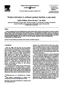
Fig. 1. Example of Graphical User Interface.
artist, price, etc. At the architecture level, products are structured in two components: the kernel and the Graphical User Interface (GUI). The kernel component implements functional requirements to add elements into the collection and to order the collection. The GUI component implements visualization and interaction with the final users and the kernel component. Kernel Commonalities. The kernel manages data associated to instances of a business logic concept such as student or music store. We use an aggregation structure to represent the business concept and its related attributes. For example, a student assembles the set of attributes code, name, address, and e-mail. Any modeled business concept has a name attribute and all the products of the product line have functionality for adding data. GUI Commonalities. Graphical User Interfaces use elements like panels, lists, labels, and images, among others. All the GUI elements are grouped by different types of views. There are five types of views that are mandatory for any product: (1) main, (2) list, (3) information, (4) order, and (5) creation view. The main view is in charge of communicating the kernel and the GUI by grouping all the other views. The list view displays data related to the name attribute of created instances of the business logic concept. The information view is used to show the data related to all the attributes of created instances of the business logic concept. The order view is used to select an attribute that will be used as reference for ordering the data displayed in the information and list views. The creation view is used to enter data for new instances of the business logic concept. Figure 1 presents the GUI of a product managing information of students. Kernel Variability. The most evident source of variation is the business concept and its attributes. As we presented before, products can be created to manage data such as students, music stores, or address books. A product may (or may not) provide functionality for ordering data. If it does, data can be ordered using either the bubble or insertion algorithms.
Fig. 2. MD-SPL Approach.
GUI Variability. The user can select two different alternative views to present the data in the information view. The first one is a simple view with labels and text fields for each attribute related to the problem space concept managed by the product. Instances are displayed one-by-one such as presented in Figure 1. The second one uses a grid component. Grid component facilitates the display of many instances of the problem space concept at the same time.
3
A Model-Driven approach for Creation of SPLs
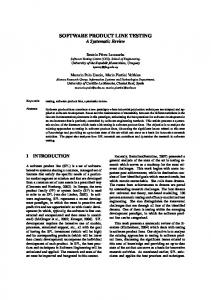
Figure 2 presents a process diagram of the activities involved in our approach. 3.1
Domain Engineering
Problem Space. During Variability Analysis (quadrant 1 of Figure 2) product line Architects create Problem Space Metamodels and Feature Models to capture commonality and variability of SPLs. Problem Space Metamodels capture metaconcepts involved in the problem space. Feature Models [3, 11, 12] capture variation points and variants. They facilitate the configuration of variable characteristics of products that are not expressed using models that conform to metamodels. For example, we create the features Simple and Grid as variants from the Information View variation point. Thus, variability is captured using metamodels and feature models. Decision about where to capture variability depends on the structure of the variability. If the variability includes structural details, and it is intended to be bound by domain experts, metamodels is the best solution. If the variability does not include structural details, but it can be bound only selecting variants from a variation point, feature models are preferred. Feature models are also a better solution to be used by stakeholders who are not experts in some specific domain, but need to bound variability only selecting specific variants. In our example (Section 2) the most evident source of variation is the business concept and its attributes. We have created a Problem Space Metamodel to
capture this structural variability. Figure 3 presents this metamodel (left) and an example of a problem space model (right) that bound structural variability to create a particular product. Our models describe only the structural information: concept type, composition, typed attributes and inheritance. To express configurable variability, we have created a feature model, Figure 4. By using it, product Designers can configure products with (or without) the functionality for Ordering data. Designers can also chose ordering data using either the Bubble or Insertion algorithms. Designers can select the GUI to present data in the Information View, it can be either the Simple or the Grid view. Solution Space. During Architecture Development (quadrant 2 of Figure 2), product line Architects create Product Line Architecture Metamodels, which capture metaconcepts involved in the solution space: (1) software design metaconcepts and/or (2) metaconcepts related to specific technology platforms. According to valid configurations made on the feature model, problem space models are transformed into Product Line Architecture models and after into the source code of products. In our example, we have created two metamodels to represent the product line architecture. One of them captures concepts involved in the kernel, the other captures GUI concepts. Figure 5 presents the GUI metamodel. Note that the abstract metaconcept Information is specialized in Simple and Grid metaconcepts. Thus, for example, if the Simple feature is selected in a configuration, a Simple element that conforms to the Simple metaconcept must be created, and then, the product will have a GUI using labels and text fields in the Information view. Product line Architects create Transformation Programs to transform models. For example, we create four programs to transform: (1) problem space models into GUI models, (2) problem space models into kernel models, (3) GUI models into Java source code of GUI components, and (4) kernel models into Java source code of kernel components. We use this sequence of model transformation programs to incrementally add design decisions to models until to obtain products according to user choices. A transformation program consists of a set of
Fig. 3. Problem Space Metamodel and Model.
Fig. 4. Feature Model.
Fig. 5. Graphical User Interface Metamodel.
Transformation Rules which in turn are sequences of instructions. We use imperative instructions such as those described in the QVT Operational Mapping language specification [13] or the xPand language reference [14]. In particular, an instruction can be the call to other transformation rule. Figure 6 presents an example of a transformation rule to transform Concept elements, from problem space models (Figure 3), into Element elements from GUI models (Figure 5). The rule is built using the xPand language. First, an element is created (line 2). After, all the conceptAttributes related to the concept received as argument, are transformed into elementAttributes using the createEleAttFromConAtt rule (line 4). Created elementAttributes are added to the list of attributes of the created element (line 5). Finally, the element is returned. Besides this kind of simple rules, product line Architects create complex rules with richer transformation logic. Two types of transformation rules are created: base and specific transformation rules. Base transformation rules contain the instructions to derivate commonalities of products. Specific transformation rules contain the instructions to derivate the variability associated to valid choices done on feature models. Thus, product line Architects create programs including base transformation rules to generate commonalities of products. Those programs must be adapted to include specific transformation rules and then to generate variability of products. For example, the program created to transform problem space models into GUI models includes base rules to create the common views to every product. We must adapt
1 create Element createElementFromConcept(Concept concept):{ 2 let element = new Element(); 3 for all conceptAttribute in concept.setOfAttributes do{ 4 let elementAttribute = createEleAttFromConAtt(conceptAttribute); 5 element.setOfAttributes.add(elementAttribute); 6 } 7 return element; 8} Fig. 6. Transformation Rule Example.
this program to include the specific rules to create an information view using either a grid component when the Grid feature is selected in a particular configuration, or text fields and labels when the selected is the Simple feature. Then, Decision Models are created. They manage the information about (1) model transformation programs and base transformation rules required to derivate the commonalities of product line members; (2) links between variants and specific transformation rules that are necessary to create model (or source code) structures associated to variants, and (3) what and when transformation programs and their base transformation rules must be adapted to generate products including specific variants. 3.2
Application Engineering
During Product Configuration (quadrant 3 of Figure 2) product Designers create Problem Space Models and Configurations to configure particular products. Configurations include selected variants from Feature Models. During Product Realization (quadrant 4 of Figure 2), model transformation programs are executed to transform the model artifacts into source code of product line members. The execution implies to process the current Configuration and the Decision Model to adapt the programs according to selected variants. Next section presents our proposal to manage (model and process) Decision Models.
4
Product Derivation based on Decision Models
Decision models are the base of our mechanism to derivate products including variability. They capture the execution ordering to be performed by the model transformation engine to derivate configured products. 4.1
Concepts involved in Decision Models
We have defined transformation programs as sets of model transformation rules with an ordering to execute them. We name Workflow to a sequence of transformation programs. In our example, we create one workflow with the four programs
that we use to transform problem space models until to obtain products. These transform, in the following order: (1) problem space models into GUI models, (2) problem space models into kernel models, (3) generated GUI models into Java source code of GUI components, and (4) generated kernel models into Java source code of kernel components. We call them respectively: (1) PS2GUI, (2) PS2Kernel, (3) GUI2Code and (4) Kernel2Code. Thus, the first information we capture in our decision model is the required workflow to derivate product line members. Figure 7 presents part of the decision model created for our illustrative example. Under the Workflow root element, we have created the four TransformationProgram elements. Two of them transform its source model into target models (PS2GUI and PS2Kernel). The others transform their source models into Java source code (Kernel2Code and GUI2Code). Each transformation program uses a set of rules to perform its transformations. For example, such as we presented in Section 3.1, to transform problem space models into GUI models, we create the base rule createElementFromConcept, which in turn uses the base rule createEleAttFromConAtt (Figure 5). We also create a base rule to create the common GUI views for every product of the SPL, createCommonViews, which in turn uses the base rule createInformationView, between others.
Fig. 7. Decision Model
Modeling the information of transformation programs, and the base transformation rules they use, facilitates the derivation of products including commonalities of products. However, to derivate products including spe-
cific variants, we have to execute specific transformation rules. We capture in our decision model, the information of the specific rules we need to derivate products. For example, the transformation program PS2GUI uses the specific rules createComparableAttribute, createGridComponent, and createSimpleComponent. The first one creates GUI Comparable elements from problem space Attribute elements when the Ordering feature is included in a product configuration. The second one creates a GUI Grid element when the Grid feature is included in a product configuration. The third one creates a Simple element when the included is the Simple feature. Our mechanism to adapt transformation programs, executing specific transformation rules when variants are included in configurations, is supported by Aspect-Oriented Programing (AOP) [9, 10]. Recent work (e.g. [15]) has shown that AOP is a valuable complement for Model Driven Engineering regarding the automatic transformation of models. We capture in decision models information about Aspects that must be executed to adapt model transformation programs. Aspects maintain the information of what and when base transformation rules must be intercepted (joinpoints) and what specific transformation rules must be then executed (advices). For example, we create an aspect that alter the behavior of the transformation program PS2GUI, by applying the specific rule createComparableAttribute, when the Comparable feature is selected and the base rule createEleAttFromConAtt is called. In our approach we only deal with around advices. This aspect could be codified as presented in Figure 8. Figure 9 presents part of our decision model modeling the information of two Aspects created to adapt the transformation program PS2GUI. The CreateComparable aspect is executed when the Comparable feature is selected and the base rule createEleAttFromConAtt is called. The CreateGrid aspect is executed when the Grid feature is selected and the base rule createInformationView is called. We have created a metamodel to guide the creation of decision models. Figure 10 presents our decision metamodel. This includes the required metaconcepts to capture Workflow, TranformationProgram, TransformationRule and Aspect elements. However, we deal with one clear restriction. Note that our joinpoints only include information about one feature and its related state (se-
1 public aspect CreateComparable:{ 2 pointcut callPointcut( ) : 3 call(createEleAttFromConAtt(Attribute) && Comparable isSelected); 4 around : callPointcut( ){ 5 createComparableAttribute(Attribute); 6 } 7 } Fig. 8. Transformation Aspect Example.
Fig. 9. Decision Model including Aspects.
lected or no-selected). This implies that we only can adapt programs when the presence of a feature (set in a particular state) in every valid configuration, always implies the same adaptation. It means that the behavior related to a feature is independent of the behavior related to any other feature. 4.2
Product Derivation
The process of product derivation transforms problem space models into products of the SPL based on configurations done by product Designers. The decision model is the base to build the required model transformation schedule that will be executed by the model transformation engine to derivate products including variability. To derivate products we have used as engine, the one provided by openArchitectureWare (oAW)3 . oAW is a MDD framework integrated into Eclipse. At the core of oAW, there is a model transformation engine allowing the definition of model transformation workflows by sequencing diverse oAW components. oAW has some pre-built components that facilitate the reading and instantiation of models, checking them for constraint violations, and transforming them into other models or source code. Model transformation workflows are built using XML files that describe the model transformation programs necessary to be executed in a generator run. 3
http://www.openarchitectureware.org
Fig. 10. Decision Metamodel
To manage Aspect elements, oAW provides a component that facilitates the definition of model transformation interceptors. This is called the transformationAspect component. The component allows to define a transformation rule to be intercepted when a particular feature is selected in a configuration. Configurations are expressed in feature models created using the pure::variants tool4 , and they can be loaded and query using two particular oAW components. Advices are created as a special type of transformation rule that is executed in the context of a transformationAspect component. Creating Model Transformation Workflows in oAW. As part of our mechanism to derivate products including variability, we have created a model-to-text transformation rule to transform our decision models into text files (oAW workflows) that can be read by the oAW engine. oAW workflows are described by XML text files that are neither easy to write nor to read, specially when product derivation implies many transformations and adaptations. Thus, we automatically generate those text files departing from a perspective based on modeling. Figure 11 presents a part of the oAW workflow we generate for our decision model. First, the current configuration model is loaded (line 2) to be query during the execution of the workflow. After, the current problem space model is loaded and stored in the local variable problemSpace (line 3-6). The problem space model is transformed using the transformation program PS2GUI (line 13), and a GUI model is generated, GUIModel (line 14). The whole transformation activity is identified as problemSpace2GUI (line 12). This transformation is intercepted when the feature Grid appears with the state isSelected in the current loaded configurationModel (line 7), and the specific rule createGridComponent is executed. The base transformation rule that is called inside the PS2GUI program, and for which its behavior is changed, is defined in another text file. In this case, it is the createCommonView base rule. 4
http://www.pure-systems.com
1 2 3 4 5 6 7 8 9 10 11 12 13 14 15 16 Fig. 11. oAW Workflow Example.
5
Comparison with other Approaches
In this paper we are interested on Model-Driven approaches and their strategies to derivate products taking into account user choices. Atkinson et al. [4] propose the Kobra approach. Kobra is a method for component-based product line engineering with UML. In KobrA an explicit and textual Decision Model is proposed to relate to each variant the architectural decision at the solution space. Decision models are devised as a treelike check list. To configure a product, the user goes through the list answering questions which answers refer to architectural model elements that must be included in the final architecture. This approach requires the intervention of product designers to modify models according to answers provided by decision models. This makes the approach for product derivation error prone. Czarnecki and Antkiewicz [8] capture variation points and variants using feature modeling. The product line architecture is modeled using model templates that are useful to create models such as class or activity diagrams. To relate variants and the model elements required to create configured products, the elements of a model template are annotated using presence conditions and meta-expressions. These annotations are defined in terms of features, and can be evaluated with respect to a feature configuration. Once a configuration is created based on feature models, model templates are used to create specific products. This approach couples variability models to the transformation rules. This makes difficult the maintenance and reuse of transformation rules and/or variability models. Similar to Czarnecki and Antkiewicz, Tessier et al. [5] use feature modeling to capture variability of SPLs, and model templates to capture the product line
architecture. Tessier et al. use explicit and independent decision models to capture relationships between groups of variants and the model transformations that must be executed, departing from models representing the product line architecture, to derivate products. This approach maintains separately the information of variants and its related model transformation rules, and use decision models to capture relationships between them. However, it does not provide a mechanism to compose or adapt model transformations according to configurations. Voelter et al. [16] capture variations creating (1) rich problem space metamodels and (2) feature models. The product line architecture is modeled using metamodels that constrain the creation of architecture models for configured products. Decisions about how problem space models are transformed into architectural models, based on configurations, are captured in text files. This approach does not provide a systematic way to build such text files, which are neither easy to manage nor adapt nor reuse. The work presented in this paper is an improvement of the one presented in [17]. In such a work, a special type of transformation rules, called control transformation rules, is used to relate variants to specific transformation rules. Control rules contain the logic to decide what and when specific transformation rules must be executed to derivate products including some configured variability. Such as in [8], this mechanism integrates in transformation rules the required logic of composition to derivate (variable) products. This modularization problem makes difficult to manage independently traceability information between variants, their related transformation rules, and the base rules required to derivate commonalities of products. Our approach provides a mechanism to model and process the relationships between variants and transformation rules solving problems related to modularization. Our mechanism to process and adapt model transformation programs, based on Aspect-Oriented Programing, enables separation of concerns and flexible adaptation of transformation programs.
6
Conclusions and Future Work
We have presented decision models as the base of our mechanism to derivate Software Product Lines. Decision models facilitate the adaptation of model transformation programs required to derivate configured products including variability. They manage the information about (1) model transformation programs and base model transformation rules required to derivate the commonalities of product line members; (2) links between variants and specific transformation rules that are necessary to create model (or source code) structures associated to variants, and (3) what and when model transformation programs included must be adapted to generate products. We have introduced our strategy to adapt model transformation programs intercepting and advising base transformation rules. Our proposal has introduced a strategy, based on Aspect-Oriented Programing, to modularize and compose transformation rules in a way that enable easy reuse, maintenance and evolution of transformation rules and variability models. For this, we maintain transfor-
mation logic in model transformation rules, and we capture required composition logic to derivate products including variability, in decision models. Thus, we decouple transformation and composition logic facilitating the traceability management of variants and its related transformation rules, to improve evolution and maintenance of SPLs. Currently our approach considers only structural models. For future work we will study the implications of using metamodels to designate behavior. We also will work on the implications of including a variant (feature) in different configurations when its transformation and composition logic depends of the presence of other features.
References 1. Bosch, J.: Design and Use of Software Architectures: Adapting and Evolving a Product-Line Approach. Addison-Wesley, Boston, MA, USA (2000) 2. Pohl, K., B¨ ockle, G., van der Linden, F.: Software Product Line Engineering: Foundations, Principles, and Techniques. Springer, Berlin (2005) 3. Czarnecki, K., Helsen, S., Eisenecker, U.: Formalizing Cardinality-Based Feature Models and their Specialization. Software Process: Improvement and Practice 10(1) (2005) 7–29 4. Atkinson, C., Bayer, J., Muthig, D.: Component-Based Product Line Development: The KobrA Approach. In: Proc. of 1st SPLC, Norwell, MA, USA (2000) 289–309 5. Tessier, P., G´erard, S., Terrier, F., Geib, J.M.: Using Variation Propagation for Model-Driven Management of a System Family. LNCS 3714 (2005) 222–233 6. Greenfield, J., Short, K., Cook, S., Kent, S.: Software Factories: Assembling Applications with Patterns, Models, Frameworks, and Tools. Wiley (August 2004) 7. Stahl, T., Voelter, M., Czarnecki, K.: Model-Driven Software Development: Technology, Engineering, Management. John Wiley & Sons (2006) 8. Czarnecki, K., Antkiewicz, M.: Mapping Features to Models: A Template Approach Based on Superimposed Variants. In: GPCE. LNCS 3676 (2005) 422–437 9. Kiczales, G., Lamping, J., Menhdhekar, A., Maeda, C., Lopes, C., Loingtier, J.M., Irwin, J.: Aspect-Oriented Programming. LNCS 1241. Springer, New York (1997) 10. Filman, R.E., Elrad, T., Clarke, S., Sit, M.A., eds.: Aspect-Oriented Software Development. Addison-Wesley, Boston (2005) 11. Kang, K., Cohen, S., Hess, J., Nowak, W., Peterson, S.: Feature-Oriented Domain Analysis (FODA) Feasibility Study. Technical Report CMU/SEI-90-TR-21 (1990) 12. Gomaa, H., Shin, M.E.: Automated software product line engineering and product derivation. In: Proc. of the 40th HICSS, Washington, DC, USA (2007) 285+ 13. Object Management Group (OMG) : Meta Object Facility (MOF) 2.0 QVT Specification Version 1.0 (2008) 14. openArchitectureWare (oAW): openArchhitectureWare 4.3 Manual. xPand Language Reference (2008) http://www.openarchitectureware.org/. 15. Third Workshop on Models and Aspects - Handling Crosscutting Concerns in MDSD, at ECOOP, Berlin, Germany (July 2007) 16. Voelter, M., Groher, I.: Product Line Implementation using Aspect-Oriented and Model-Driven Software Development. In: Proc. of the 11th SPLC. (2007) 233–242 17. Garces, K., Parra, C., Arboleda, H., Yie, A., Casallas, R.: Variability Management in a Model-Driven Software Product Line. Avances en Sistemas e Inform´ atica 4(2) (2007) 3–12