on a single processor which makes the overall hardware-software system design ..... We call such an implementation of a loop construct in software a pseudo-static ..... MIP 9115432 and by a fellowship provided by the Center for Integrated ...
Program Implementation Schemes for Hardware-Software Systems Rajesh K. Gupta
Claudionor N. Coelho, Jr.
Giovanni De Micheli
Computer Systems Laboratory Departments of Electrical Engineering and Computer Science Stanford University, Stanford, CA 94305-4055 To appear in IEEE Computer - January 1994 Abstract We consider mixed system designs that are made of interacting hardware and software components. The hardware component consists of a re-programmable component, like an off-the-shelf processor, and application-specific chips. The software component consists of a set of concurrently executing program fragments, called threads. We have considered the problem of generating hardware and software components from a given system model under input/output data rate constraints in [1]. In this paper we present schemes for implementation of the software component of mixed system designs. The primary motivation for software implementation schemes is to provide a low overhead scheme for concurrent software implementation on a single processor which makes the overall hardware-software system design feasible.
1 Introduction Prompted by the success in recent years in synthesis of large-scale integrated circuits either as a single chip or as a collection of chips [2] [3], attention has now been focused on synthesis of systems where the target architecture contains application-specific as well as general purpose re-programmable components. The re-programmable components of a system architecture refers to a microprocessor like the Mips R3000 which executes part of the system functionality implemented as programs assisted by dedicated ASIC hardware. The motivation for such a target architecture comes from the realization that most system designs used in dedicated applications, i.e., embedded systems consist of mixed components that blend ASIC chips with processors, memory and other special purpose modules. The ASIC components are chosen to complement performance or add functionality not achievable by pure program implementations. Recent advances in hardware synthesis and the proliferation of advanced and inexpensive microprocessors and processor cores have lead to the emergence of research interests in hardware-software co-design [4, 5, 6, 7, 8, 9, 10]. Synthesis of systems containing re-programmable components can be thought of as extension of highlevel synthesis techniques to systems containing ‘generalized resources’. However, due to differences in the computation model of the operations implemented in re-programmable and application-specific components, the overall problem of system synthesis is much more complex. The re-programmable components implement system functionality in an instruction-driven software component as an ordered 1
Gupta, Coelho, De Micheli: Program Implementation Schemes
2
HDL HDL Specification compilation
Graph Model constraint analysis partitioning
Program Graph
ASIC Graph Model
Interface
Multi−thread Program Generation
code synthesis
interface gen
C Program strctural synthesis
System Environment Model
compilation System IO
Assembly Program
ASIC Netlist
POSEIDON (Simulation)
Mixed System Implementation
Figure 1: System Synthesis Procedure set of machine instructions with a statically allocated memory space, whereas the application-specific hardware components essentially operate as data-driven reactive computational elements. Because of this difference in the hardware and software components, the problem of system synthesis is formulated as a hardware-software co-synthesis problem[11].
2 An Overview of our Co-synthesis Approach Figure 1 illustrates the overall approach to synthesis of systems containing both hardware and software components. We model system behavior using a hardware description language, HardwareC [12] language that has a C-like syntax and supports timing and resource constraints. HardwareC supports specification of unbounded and unknown delay operations that can arise from data dependent decisions and external synchronization operations. The choice of a hardware description language to model system functionality is not necessarly an ideal approach due to limitations that are inherent in such a model. However, it does provide the benefits developing a co-synthesis approach that extends and builds upon techniques for synthesis of hardware. Further, the particular choice of HardwareC is immaterial for the co-synthesis formulation, and one could use other HDLs such as Verilog or VHDL. The input HDL description is compiled into a system graph model based on data-flow graphs [11, 13]. The system graph model consists of vertices representing operations, and edges which represent serialization among operations.
Gupta, Coelho, De Micheli: Program Implementation Schemes
3
Overall the system graph model is composed of concurrent data-flow sections which are ordered by the system control flow. Associated with input/output statements, the user can specify corresponding constraints on input/output data rates. The input (output) rate constraints refer to bounds on the rates at which data is required to be consumed (produced). For a discussion of the constraint analysis the reader is referred to [13]. The system graph model is partitioned based on feasibility of the overall system implementation and satisfaction of applicable data-rate constraints. One such scheme relies on identifying unbounded delay operations[1, 14]. As a result of system partitioning, we have a set of concurrently executing ‘hardware’ and ‘software’ models. These models consist of hierarchical acyclic system graph models. We consider input/output operations related to message-passing and data-dependent loops to be unbounded delay operations. Since data-dependent operations may offer unbounded delays it becomes necessary to schedule these operations dynamically. Therefore, we refer to data-dependent delay operations as points of synchronization in the system model. Our approach to synthesis of hardware under relative scheduling formulation has been described in detail elsewhere [12]. Briefly, the relative scheduling formulation makes it possible to achieve a data-driven dynamic schedule of operations with respect to synchronization points. Due to inherently different model and rate of computation between hardware and software modules, it is necessary to allow multiple executions of individual hardware and software models in order to achieve high system throughput. Differences in rates of computation causes variation in the rates of communication across different models. In order to facilitate this form of distributed computation, appropriate buffering and handshake mechanisms between hardware and software components are needed [14]. The software graph models are then serialized to minimize temporary register storage requirements.From the serialized graph models, we generate a corresponding C-code description. The C-code is then compiled into assembly code for the target processor using existing software compilers. We verify the correctness of implementations by using an event-driven simulator named Poseidon, that performs concurrent execution of multiple functional models implemented either as a program or as application-specific hardware [14]. Poseidon supports simulation of assembly code for the DLX microprocessor [15], a RISC oriented load/store processor that supports instruction-set architecture of the commercially available Mips R3000 processor, and assembly code for the 8051 microcontroller. The hardware component of system design can be simulated either before or after the structural synthesis phase. The former simulation is performed at the system graph level and the latter simulation is performed at the logic level. Input to Poseidon consists of model declarations, interconnections and corresponding interface. Each model has an associated clock signal and clock cycle-time used for its simulation. The interface is specified by its components, such as wires, queues, registers, and memories, and their protocols. For example, the protocol for a data-transfer to or from a queue is specified by guarded commands. Section 5 presents an example of interface protocol specification in Poseidon. In this paper, we focus on the problem of generation of the software components from the graph model that is output of system partitioning as shown by the shaded area in Figure 1.
Target Architecture and Assumptions We choose a target architecture that contains the essential elements of hardware-software systems. As shown in Figure 2, the target architecture consists of a general-purpose processor assisted by application-
Gupta, Coelho, De Micheli: Program Implementation Schemes
4
MEMORY ML Program User Data Interface Buffer
ASIC MICROPROCESSOR ASIC
Re-programmable Component
Application-Specific Components
Figure 2: Target System Architecture specific hardware components. The following lists the relevant assumptions relating to target architecture. � We restrict ourselves to use of a single re-programmable component because presence of multiple re-programmable components requires additional software synchronization and memory protection considerations to facilitate safe multiprocessing. Multiprocessor implementations also increase the system cost due to requirements for additional system bus bandwidth to facilitate inter-processor communications. We make this simplifying assumption in order to make the synthesis tasks manageable. � The memory used for program and data-storage may be on-board the processor. However, the interface buffer memory needs to be accessible to the hardware modules directly. Because of the complexities associated with modeling hierarchical memory design, so far we have considered the case where all memory accesses are to a single-level memory, i.e., outside the re-programmable component. The hardware modules are connected to the system address and data busses. Thus all the communication between the processor and different hardware modules takes place over a shared medium. � The re-programmable component is always the bus master. Almost all processors come with facilities for bus control. On the other hand, inclusion of such functionality on the applicationspecific component would greatly increase the total hardware cost. � All the communication between the re-programmable component and the ASIC components is done over named channels whose width (i.e. number of bits) is same as the corresponding port widths used by read and write instructions in the software component. The physical communication takes place over a shared bus.
Gupta, Coelho, De Micheli: Program Implementation Schemes
5
� The re-programmable component contains a ‘sufficient’ number of maskable interrupt input signals. For purposes of simplicity, we assume that these interrupts are unvectored and there exists a predefined unique destination address associated with each interrupt signal.
3 Implementation of Software Components As mentioned earlier, the system ‘software component’ is described as a set of hierarchical acyclic graph models where the vertices represent operations and edges represent dependencies. Through the use of hierarchy to describe calls and loops, the graph model pushes the uncertainty of conditional execution paths into the uncertainty of delay. The uncertainty of loop executions manifests itself as the uncertainty of the number of times the a called graph model is executed. Example 1 shows a HardwareC process description containing message-passing receive, conditional and loop operations. Example 1:
Example of a HardwareC process with unbounded delay operations process example (a, b, c) in port a[8] ; in channel b[8] ; out port c ; { boolean x[8], y[8], z[8] ; x = read(a); y = receive(b); if (x > y) z = x - y ; else z = x * y ; while (z >= 0) { write c = y ; z = z - 1 ; } }
Notes on execution semantics: (1). A process in HardwareC executes concurrently with other processes in the system specification. A process restarts itself upon completion of the last operation in the process body. Thus there exists an implied outer-most loop that contains the body of the process model. In other languages, this loop can be specified by an explicit outer loop statement. (2). Operations within a process body need not be executed sequentially (as is the case in a process specification in VHDL, for example). A process body can be specified with varying degrees of parallelism such as parallel, data-parallel or sequential. 2
Figure 3 shows the corresponding hierarchical graph model for the process example that consists of two graphs, labeled G0 and Gloop . The bold-circles indicate operations with unbounded or unknown execution delays. Depending upon the points of synchronization in a model, the graph can be implemented as a single or multiple routines. In absence of multiple points of synchronization, a simple graph model can be implemented as a single routine. A hierarchical system model is implemented as a set of routines where each routine corresponds to a graph in the model hierarchy. A program implementation of a graph is referred to as a program thread due to the fact that the operations of the graph model are serialized in software. Thus, the software component consists of a set of program threads. The program threads may be hierarchically related. In addition, some program threads may need to be executed concurrently based
Gupta, Coelho, De Micheli: Program Implementation Schemes
6
Source nop
rcv
rd
cond c c
c’
mpy
sub
c
c’
Source
join
loop
nop
Sink
nop
wr
sub
nop
Sink
Figure 3: Example of a graph model containing unbounded and unknown delay operations on the concurrency among the corresponding graph models. Concurrency between program threads can be achieved by using an inter-leaved execution model as explained later in this section. A program thread may be initiated by a synchronization operation, such as a blocking receive operation (rcv synch). However, within each thread all operations have fixed delay. The (unknown) delay in executing the synchronization operation appears as a delay in scheduling the program thread and it is not considered a part of the thread latency. Therefore, for a given re-programmable device the bound on latency of each thread is known statically. Referring to the example in Figure 3, there are two program threads T0 and Tloop . Thread, T0 consists of the receive operation followed by the port read operation etc. while the other thread consist of serialized operations in the corresponding graph body. T0 rcv synch read cond eval cond jump op add op mpy detach
Tloop loop synch write op detach
Though only a feature of representation, this use of hierarchy is well suited to eventual implementation of the software component as a set of program routines. Upon synchronization, all the operations in a given graph model are eventually executed. Thus, the corresponding routines can be constructed with known and bounded latencies as explained earlier. As with the graph model, the uncertainty due to data-dependent delay operations is related to invocations of the individual routines. A software implementation consisting
Gupta, Coelho, De Micheli: Program Implementation Schemes
7
of dynamic invocations of fixed latency program threads simplifies the task of software characterization for satisfaction of data rate constraints. Satisfaction of imposed data rate constraints depends upon the performance of the software component. Even in presence of unbounded delay operations bounds on software performance can be determined based on its implementation of program threads. In the following sections, we describe a code-level transformation of the data-dependent loop operations that makes it possible to observe imposed input/output rate constraints. In cases where such transformations are not possible, we use processor interrupts along with bounds on number of interrupts and interrupt latencies to ensure satisfaction of rate constraints.
Rate constraints and software performance The data rate constraints on the inputs and outputs of the software component are derived based on the corresponding constraints on system inputs and outputs. A data rate constraint on an input (output) specifies a lower bound — in terms of samples/sec — on the rate at which the particular I/O data should be consumed (produced). In case of a deterministic software component, that is, software component with known and bounded execution delays, precise data rates can be computed and checked against corresponding data rate constraints. However, the presence of an unbounded-delay operation between consecutive read (write) operations requires computation of statistical measures — such as distribution of input data value and inter-arrival time — in order to determine the rate of data production and consumption. A major contribution to the variability of data rates is due to the data-dependent loop operations since the delay due to these operations consists of active execution times rather than ‘busywait’-type delays encountered by other synchronization operations. In some cases, the need for statistical measures can be avoided by transforming the dynamic loop execution model into a corresponding pseudostatic loop execution model as follows. Consider, for example, a software component that consists of reading a value followed by a data-dependent delay operation shown in Example 2. Example 2:
Consider a mixed implementation shown by the figure below.
port x
ASIC ρ samples/sec
Processor
The ASIC component sends to the processor some data on port x at an input rate constraint of � samples/sec. The function to be implemented by the processor is modeled by the following HardwareC process fragment. process test(x, ...) in port x [SIZE]; { ... read x ; while (x >= 0) { x = x - 1 ; } }
| | | | | | | | | |
Thread T1
Thread T2
read detach
loop_synch x = x - 1 detach
Gupta, Coelho, De Micheli: Program Implementation Schemes
8
x is a boolean array that represents an integer. In its software implementation, this behavior is translated into a set of two program threads shown on the right, where one thread performs the reading operations, and the other thread consists of operations in the body of the loop. For each execution of thread T1 there are x execution of thread T2. 2
For the HardwareC process in Example 2, the interval between successive executions of the read operation is determined by the overall execution time of the while statement. Due to this variable-delay loop operation, the input data rate at port x is variable and is dependent upon value of x as a function of time. For each invocation of thread T1 there are x invocations of thread T2. In other words, thread T1 can be resumed after x invocations of thread T2. In absence of any other data-dependency to operations in the loop body, thread T1 can be restarted before completing all invocations of thread T2 by buffering the data transfer from thread T1 to T2. Further, if variable x is used only for indexing the loop iterations, the need for inter-thread buffering can be obviated by accumulating value of x into a separate loop counter as shown in example below. We call such an implementation of a loop construct in software a pseudo-static loop based on the fact that an upper bound on the number of iterations of the loop body is statically determined by the data rate constraints on inputs and outputs that are affected by the data-dependent loop operation. A pseudo-static loop implementation assumes that there exists a repeat-count counter associated with every loop and a loop body is required to be executed as long as its repeat-count is a non-zero number. Additionally, the repeat-count is not used by the corresponding loop body for any purposes other than keeping a count of number of iterations remaining. Under such conditions, the above component can be transformed into two program threads where one thread reads port x and increments the repeat-count for the loop body contained in the other thread. Example 3:
Transformation of data-dependent loop in Example 2 into a pseudo-static loop process test(x, ...) in port x [SIZE] { integer repeat-count = 0 ;
| | | | | read x ; | repeat-count = repeat-count + x ; | while (repeat-count >= 0) | { | | repeat-count = repeat-count-1 | }
Thread T1
Thread T2
read add op detach
loop_synch repeat-count-detach
}
(1). For each execution of thread T1 there is an upper bound on the maximum number of executions of thread T2. This bound is determined by an input data rate constraint. (2). Initialization of variables is performed during system RESET state.
2
In this case, we can provide a bound on the rate at which port is read by ensuring that the read thread, T1, is scheduled, say after utmost m iterations of the loop body. Due to accumulation of repeat-count additional care must be taken to avoid any potential overflow of this counter. [Generally, overflow can be avoided if m is greater than or equal to the average value of x. In the extreme, it can be guaranteed not to overflow if m is at least maximum of x which is equivalent to assigning worst-case delay to the loop operation].
Gupta, Coelho, De Micheli: Program Implementation Schemes
9
Decoupling output data rate from software non-determinism Due to unbounded delay operations in the software component that is translated into a data-dependent number of invocations of some threads of execution, use of pseudo-static loops may not always be possible or it may lead to implementations that under-utilize the system bus bandwidths, for example, by reserving worst case data-transfer rates for some I/O operations. With concurrent threads, to a certain extent, we can insulate the input/output data rates from variable delays due to other threads by buffering the data transfers between threads. Thus, the inter-thread buffers hold the data in order to facilitate multiple executions among program threads. Threads containing specific input/output operations are scheduled at fixed intervals via processor interrupt routines as shown in the Example 4 below. In this scheme, finite-sized buffers are allocated for each data-transfer between program threads. In order to ensure the input/output data rates for each thread, we associate a timer process with every I/O operation that interrupts the processor once the timer expires. The associated interrupt service routine performs the respective I/O operation and restarts the timer. In case a data is not ready the processor can send the previous output and (optionally) raise an error flag. Example 4:
Implementation of program threads in Example 2 with inter-thread buffer.
Thread T2
Timer Process
T1 (interrupt service routine)
loop_synch x = x - 1 detach
timer-- per clock tick if (timer == 0) interrupt
read x load timer = CONSTANT enqueue (x) on dFIFO
Thread T1 is now implemented into an interrupt service routine that is invoked at each expiration of the timer process. Timer process represents a processor timer (or an external hardware timer) that is used to generate interrupts at regular intervals. The interruption interval CONSTANT is determined by the rate constraint and latencies of interrupt service routines. The buffer between threads T1 and T2 is called dFIFO in the interrupt service routine. 2
This scheme is particularly helpful in case of widely non-uniform rates of production and consumption. In this case, data transfer from processor to ASICs is handled by the interrupt routines thereby leading to a relatively smaller program size for the cost of increased latencies of the interrupt service routines. Section 6 presents implementation costs and performance of this scheme. Next we consider the problem of software synchronization and scheduling mechanisms to make a hardware-software system design feasible.
4 Control Flow in the Software Component Our model of software component relies on the sequential execution of each thread of execution. Concurrency between threads is achieved through interleaved execution of the threads. Multiple program threads may be created out of a graph model each starting with an unbounded-delay operation. Therefore, software synchronization is needed to ensure correct ordering of operations within the program threads and between different threads. In presence of multiple threads of executions due branching and loop operations, the control flow between threads is represented by a directed flow graph, the nodes of which are individual program threads
Gupta, Coelho, De Micheli: Program Implementation Schemes
10
and edges indicate control dependencies. Since the total number program threads and their dependencies are known statically, the programs threads are constructed to observe these dependencies. The threads are identified by unique tags. A run-time FIFO, called control FIFO, maintains the identifier tags of the threads that are ready to run based on control flow (while they may still be waiting for data). Before detaching, each thread performs one or more enqueue operations to the FIFO for its successor threads as shown in Example 5 below. Example 5:
Inter-thread control dependencies. before T1 Thread T1
T1
T2
T3
Flow Graph
T1
enqueue (T2) on cFIFO enqueue (T3) on cFIFO detach
after T1 T2 T3
ControlFIFO (cFIFO)
Thread
refers to the (linearized) set of operations from the corresponding graph models. Control dependency from thread T1 to T2 is built into the code of T1 by the enqueue operation on the control FIFO. 2
A thread dependency on more than one predecessor thread (that is a multiple indegree (fanin) node in the flow graph) is satisfied by ensuring multiple enqueue operations for the thread by means of a counter. For example, a thread node with a indegree of 2 would contain a synchronization preamble code as indicated by the while statement shown in Example 6 below. Example 6:
Thread with multiple input control dependencies. Thread T1 while (count != 2) { count = count + 1; detach } count = 0 enqueue on cFIFO detach
T2
T3
T1
T1 is enqueued by T2 and T3, since there are dependencies from T2 and T3 into T1. Therefore, T1 must wait for the control to be transfered from T2 and T3. This control transfer is achieved by counting the number of times T1 is enqueued in the control FIFO. 2
Control transfer for multiple fanin nodes entails program overheads that add to the latency of the corresponding threads. For this reason, an attempt should be made to reduce multiple dependencies for a program thread through a careful dependency analysis. In case of multiple outdegree nodes in the flow graph, a necessary serialization among enabling of successor threads occurs.
Gupta, Coelho, De Micheli: Program Implementation Schemes
11
The problem of achieving concurrency through interleaved execution in the software component was considered in [14]. The different program threads can be implemented as program subroutines that operate under a global task scheduler (or the main program). It was shown that the overheads in terms of number of cycles for each inter-thread control transfer operation can be reduced significantly by placing program subroutines in a co-operative, rather than hierarchical, relationship to each other by implementing them as Coroutines [16]. For the DLX microprocessor a coroutine implementation of program threads constitutes an overhead of 19 cycles. This low overhead comes from the fact that coroutine transfers are determined at compilation time in our model, and thus efficient use of registers prevents the high overhead costs of more general transfer schemes. Another scheme for implementation of the software component is to construct a program routine using the method of description by cases [17]. In this method, we attempt to construct a single program with a unique case assignment for each thread (in a rather large conditional in the final program). A set of global state registers is used to store the state of execution of each thread. The overheads due to this scheme depends strongly upon the instruction set architecture of processor. For the DLX microprocessor, the overhead amounts to 35 cycles for each inter-thread transfer operation. In case of so-called ‘CISC’ processors this scheme reduces the overhead by reducing amount of ALU operations in favor of a slight increase in memory input-output operations.
5 Hardware-Software Synchronization Due to the serial execution of the software component a data transfer from hardware to software must be explicitly synchronized. Using a polling strategy, the software component can be designed to perform pre-meditated transfers from the hardware components based on its data requirements. This requires static scheduling of the hardware component. In cases where the software functionality is communication limited, that is, the processor is busy-waiting for an input-output operation most of the time, such a scheme would be sufficient. Further, in absence of any unbounded-delay operations, the software component in this scheme can be simplified to a single program thread and a single data channel since all data transfers are serialized. However, this would not support any branching, no reordering of data arrivals since dynamic scheduling of operations in hardware would not be supported. In order to accommodate different rates of execution of the hardware and software components, and due to unbounded delay operations, we look for a dynamic scheduling of different threads of execution. Such a scheduling is done based on availability of data. One mechanism perform such scheduling is by means of a control FIFO mentioned in the previous section which attempts to enforce the policy that data items are consumed in the order in which they are produced. The hardware-software interface consists of data queues on each channel and a (control) FIFO that holds the identifiers for the enabled program threads in the order in which their input data arrives. The control FIFO depth is sized with the number of threads of execution, since a thread execution is stalled pending availability of the requested data. Example 7 below describes the hardware-software interface. Example 7:
Hardware-Software Interface.
Figure 4 shows schematic connection of the FIFO control signals for a single data queue. In this example, the data queue is memory mapped at address 0xee000 while the data queue request signal is identified by bit 0 of address 0xee004 and enable from the microprocessor ( up en) is generated from bit 0 of address 0xee008.
Gupta, Coelho, De Micheli: Program Implementation Schemes
12
System Bus
up_en
Processor up_ab
q_rq
FIFO control logic
Data Queue ASIC 0xee000
gn
cf_ak
ControlFIFO
Figure 4: Control FIFO schematic The control FIFO is ready to enqueue (indicated by gn = 1) a process id if the corresponding data request (q rq) is high and the process has enabled the thread for execution ( up en). Signal up ab indicates completion of a control FIFO read operation by the processor. In case of multiple indegree queues, the enqueue rq is generated by OR-ing the requests of all inputs to the queues. In case of multiple-outdegree queues, the signal dequeue rq is generated also by OR-ing all dequeue requests from the queue. 2
The control FIFO and associated control logic can be implemented either in hardware as a part of the ASIC component or in software. In case the control FIFO is implemented in software the FIFO control logic is no longer needed since the control flow is already in software. In this case, the q rq lines from data queues are connected to processor unvectored interrupt lines, where the respective interrupt service routines are used to enqueue the thread identifier tags into the control FIFO. During the enqueue operations the interrupts are disabled in order to preserve integrity of the software control flow. The hardware-software interface protocol is described using guarded commands as shown in the Example 8 below. Example 8:
Specification of the control FIFO based on two threads of execution.
queue [3] controlFIFO [2]; queue [16] line_queue [1], circle_queue [1]; enqueue when (cntl.gn_line, cntl.ak_line) in controlFifo[1:0]; enqueue when (cntc.gn_circle, cntc.ak_circle) in controlFifo[1:0]; dequeue dlx.0xff000[1:0] when (dlx.0xab0000[2:2],dlx.0xab0000_rd & dlx.CLOCK) in controlFifo[1:0];
In this example, two data queues with 16 bits of width and 1 bit of depth, line queue and circle queue, and one queue with 2 bits of width and 3 bit of depth controlFIFO are declared. The guarded commands specify the conditions on which the number 1 (represented by < 0; 1 >) or
Gupta, Coelho, De Micheli: Program Implementation Schemes
13
the number 2 (represented by < 1; 0 >) are enqueued. Those numbers correspond to thread ids. The first (second) enqueue command states that the value 1 (2) should be enqueued to the controlFIFO when a request comes from the FIFO control logic — see Figure 4 — for the line (circle) data queue. The controlFIFO acknoledges the request through the signal ak line (ak circle). The dequeue command states that the microprocessor dequeues the program thread id from controlFIFO when bit 2 of a memory port at address 0xab0000 is set — in this implementation, this bit is polled by the scheduler running in the microprocessor. The program thread is stored in the first two bits of the same memory port, and the synchronization between the microprocessor and the FIFO occurs when the microprocessor reads data from the memory address 0xab0000. 2
6 Results In order to illustrate the effect of software and hardware-software interface implementation, we present design of a portion of a graphics controller that outputs pixel coordinates for lines and circles given the end coordinates (and radius in case of circle). The final implementation of the system design consists of line and circle drawing routines in the software component while the ASIC hardware performs initial coordinate generation and coordinate transfer to the video ram. The software component consists of two threads of execution corresponding to the line and circle drawing routines. Both program threads generate coordinates that are used by the dedicated hardware. The data-driven dynamic scheduling of program threads is achieved through the use of a 3-deep control FIFO. The circle and line drawing program threads are identified by id numbers 1 and 2 respectively. The program threads are implemented using the coroutine scheme described in Section 4. Example 9 shows the main program in case of a hardware control FIFO implementation. Like the line and circle drawing routines, this program is compiled using existing C-compiler. Example 9:
Main program of the graphics controller software component #include "transfer_to.h" int lastPC[MAXCOROUTINES] = {scheduler, circle, line, main}; int current = MAIN; int *controlFIFO_out = (int *) 0xaa0000; int *controlFIFO = (int *) 0xab0000; int *controlFIFO_outak = (int *) 0xac0000; #include "line.c" #include "circle.c" void main() { resume(SCHEDULER); }; int nextCoroutine; void scheduler() { resume(LINE); resume(CIRCLE); while(!RESET) { do { nextCoroutine = *controlFIFO; } while ((nextCoroutine & 0x4) != 0x4); resume(nextCoroutine & 0x3); } }
Gupta, Coelho, De Micheli: Program Implementation Schemes
14
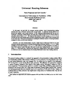
Figure 5: Graphics Controller Simulation
2 Figure 5 shows a simulation of the mixed implementation. x out and y out are the coordinates generated by the line thread routine. xcircle and ycircle are the coordinates generated by the circle thread routine. Note that these latter coordinates are generated in burst mode, since the circle thread routine explores symmetries to generate the coordinates. The values at the top of the controlFIFO are also shown in the figure. CF ready signals that the controlFIFO is never empty after initialization. We show also the synchronization between the data queues, the lines and circle threads and the scheduler. controlFIFO rd shows when the scheduler polls the controlFIFO to obtain the next thread id. controlFIFO wr shows the transfer of control-flow from the line and circle threads. Finally, ol rq (oc rq) shows when the data fifo for the line (circle) enqueues the corresponding thread ids to signal that new coordinates are already available. Table 1 compares the performance of different program implementations using control FIFO either in hardware or in software component. The hardware implementation of a control FIFO with a fanin of 3, when synthesized by program Hebe[12] and mapped to LSI 10K library of gates using program Ceres[12], costs 228 gates. An equivalent software implementation adds 388 bytes to the overall program size of the software component. Note that the cost of hardware control FIFO increases as the number of data queues increases. On the other hand, software implementation of control FIFO using interrupt routines to perform the control FIFO enqueue operations offers lower implementation cost for a 50% increase in the thread latencies. In case of software implementation of control FIFO, the enqueue and dequeue operations are described in C which are then compiled for DLX assembly. The overhead due to
Gupta, Coelho, De Micheli: Program Implementation Schemes
Program size
Scheme
Hardware CFIFO Software CFIFO Opt. Software CFIFO
(bytes)
Synchronization overhead delay (% cycles)
5972 6588 6360
0 50 29.4
15
Input data rate 01 (cycles/coordinate)
81 95 95
Output data rate 01 (cycles/coordinate) line circle ave. peak ave. peak 535.2 749.5 651
502 407 330
76.4 106.8 94
30 31 31
Table 1: A comparison of control FIFO implementation schemes
enqueue and dequeue operations is reduced further by manually optimizing the assembly code for enqueue and dequeue operations as indicated by the entry ‘Opt. Software CFIFO’. This one-time optimization of enqueue and dequeue routines, which does not affect the C-code description of the program threads, leads to a reduction in the program size and program thread overhead to 29.4% thereby improving the rate at which the data is output. Note that data input and output rates have been expressed in terms of number of cycles it takes to input or output a coordinate. Due to the data-dependent behavior of program threads, the actual data input and output rates would vary with respect to value of the input data. In this example simulation, the input rate has been expressed for a simultaneous drawing of a line and 5 pixel radius with width of 1 pixel each and the results are accurate to one pixel. An input rate of 81 cycles/coordinate corresponds to approximately 0.25 million samples/sec for a processor running at 20 MHz. Similarly, a peak circle output rate of 30 cycles/coordinate corresponds to a rate of 0.67 million samples/sec. An implementation of line and circle drawing program threads for the graphics controller example using inter-thread buffering and I/O timers mentioned in Section 3, comes to a total program size of 5788 bytes for a 62% overhead delay per program thread. Though instructive, the line and circle drawing algorithms are simple enough that their software implementation do not fully exploit the potential of a mixed implementation. However, a more computationally intensive operation like spline generation or operations involving floating point arithmetic would greatly benefit by their program implementations. As an example of complex system design, we present design of an ethernet-based network co-processor. This processor is modeled as a set of 13 concurrently executing processes which interact with each other by means of 24 send and 40 receive operations. The total HardwareC description consists of 1036 lines of code. A mixed implementation using a single program containing 17 cases using the method of description by cases for the software component takes 8572 bytes of program and data storage but it reduces the overall cost of the application-specific component by 23% from 10882 gates to 8394 gates using LSI logic 10K library of gates. The mixed implementation delegates much of execution unit and operations relating to frame assembly and dis-assembly to a software component. The mixed implementation meets the imposed performance requirements like maximum propagation delay of 46.4 �s, maximum jam time of 4.8 �s, minimum interframe spacing of 67.2 �s and input bit-rate for a 10 Mb/sec operation using ethernet protocol. Table 2 lists characteristics of the software component for the graphics controller and the network co-processor.
Gupta, Coelho, De Micheli: Program Implementation Schemes
16
Example
Program implementation
Program size bytes
Max delay cycles
Graphics controller Network coprocessor
Coroutines, Hardware CFIFO Desc. by cases, Hardware CFIFO
5972 8572
806, 859 56
Table 2: Software component for system examples
7 Summary and Conclusions Presence of re-programmable processors in target architectures promises a practical approach towards realizing complex system designs for embedded applications without associated increase in the cost of application-specific components required to implement the system functionality. Where possible, portions of system functionality can be delegated to the software component without incurring the cost of implementing these functions in the application-specific hardware components. Synthesis of systems containing both general-purpose re-programmable as well as application-specific components can be formulated as a hardware-software co-synthesis problem due to two predominantly different computation models used by the system components. Software component design for such systems poses interesting problems due to inherently serial nature of program execution that must interact with concurrently operating hardware components. In our approach to system synthesis, the software component is implemented as a set of program routines, called threads. Concurrency between program threads, achieved by inter-leaved execution of threads, preserves concurrency inherent in the system model. Further, dynamic scheduling of fixed latency threads avoids unnecessary serialization of operations in a graph model for generation of the software component. The program routines corresponding to threads can be implemented as subroutines or coroutines. A coroutine implementation reduces overheads by treating all routines symmetrically, therefore, the context information needed to be saved/restored is reduced. However, the necessity to embed control flow into the individual coroutines reduces this gain somewhat. At the same time, the ability to do intelligent dependency analysis on the system graph model can reduce this overhead. There is a tradeoff between when graph serialization is done and when program threads are generated. We construct program flow graphs that consist of potential threads as basic blocks based on points of synchronization in the system graph model. A completely serialized graph model would loose the advantage of coroutine implementation and may benefit by the subroutine implementation instead. However, the loss of all concurrency may make eventual software component in feasible with respect to the imposed data-rate constraints. We have proposed a scheme to achieve hardware-software synchronization. We have demonstrated feasibility of control FIFO-based hardware-software synchronization schemes where the FIFO control can be implemented either as a dedicated hardware or as a program. The software implementation of control FIFO reduces the size of hardware component of system design, but it increases program size and adds to the latencies of program threads. This makes the input data rate about 15% slower in case of the graphics controller example. Depending upon the objective of system synthesis either of the hardware and software alternatives can be selected and simulated using program Poseidon. Generally, an implementation that
Gupta, Coelho, De Micheli: Program Implementation Schemes
17
aims to rapidly prototype the system design would favor software component of the system design for a small loss of performance. Using the synchronization scheme proposed, we are able to synthesize and simulate mixed system designs. As example, we have presented designs of a graphics controller and a network coprocessor that employ software components to achieve part of the system functionality. Even with the simplifying assumptions relating to the target architecture, the problems of accurately characterizing software component and its synthesis are challenging problems. This work takes a first step in solving the problem of system software synthesis. Work is in progress to extend the model to include the effects of hierarchical memory schemes and reduction of communication overheads by using channel sharing and data encoding schemes.
8 Acknowledgments We acknowledge discussions with Martin Freeman. This research was sponsored by NSF-ARPA, under grant No. MIP 9115432 and by a fellowship provided by the Center for Integrated Systems and Philips. The second author was supported by the fellowship 200212/90.7 from CNPq-Brazil.
References [1] R. K. Gupta and G. D. Micheli, “System-level Synthesis Using Re-programmable Components,” in Proceedings of the European Design Automation Conference, pp. 2–7, Mar. 1992. [2] D. Gajski, Silicon Compilation. Addison Wesley, 1988. [3] R. Camposano and W. Wolf, High-level VLSI Synthesis. Kluwer Academic Publishers, 1991. [4] M. Chiodo, P. Giusto, H. Hsieh, A. Jurecska, L. Lavagno, and A. S. Vincentelli, “Synthesis of mixed software-hardware implementations from cfsm specifications,” in International Workshop on Hardware-Software Co-design, Oct. 1993. [5] A. Kalavade and E. A. Lee, “A hardware-software codesign methodology for dsp applications,” IEEE Design & Test of Computers, pp. 16–28, Sept. 1993. [6] D. E. Thomas, J. K. Adams, and H. Schmit, “A model and methodology for hardware-software codesign,” IEEE Design & Test of Computers, pp. 6–15, Sept. 1993. [7] N. Woo, W. Wolf, and A. Dunlop, “Compilation of a single specification into hardware and software,” in International Workshop on Hardware-Software Co-design, Oct. 1992. [8] E. Walkup and G. Boriello, “Automatic Synthesis of Device Drivers for Hardware/Software Codesign,” in International Workshop on Hardware-Software Co-design, Oct. 1993. [9] R. Ernst, J. Henkel, and T. Benner, “Hardware-Software Co-synthesis for Microcontrollers,” IEEE Design & Test of Computers, Dec. 1993.
Gupta, Coelho, De Micheli: Program Implementation Schemes
18
[10] M. B. Srivastava and R. W. Broderson, “Rapid-Prototyping of Hardware and Software in a Unified Framework,” in Proceedings of the IEEE International Conference on Computer-Aided Design, (Santa Clara), pp. 152–155, 1991. [11] R. K. Gupta and G. D. Micheli, “Hardware-Software Cosynthesis for Digital Systems,” IEEE Design & Test of Computers, pp. 29–41, Sept. 1993. [12] G. D. Micheli, D. C. Ku, F. Mailhot, and T. Truong, “The Olympus Synthesis System for Digital Design,” IEEE Design and Test Magazine, pp. 37–53, Oct. 1990. [13] R. K. Gupta, Co-synthesis of Hardware and Software for Digital Embedded Systems. PhD thesis, Stanford University, 1993. [14] R. K. Gupta, C. Coelho, and G. D. Micheli, “Synthesis and Simulation of Digital Systems Containing Interacting Hardware and Software Components,” in Proceedings of the 29th Design Automation Conference, pp. 225–230, June 1992. [15] J. L. Hennessy and D. A. Patterson, Computer Architecture: A Quantitative Approach, ch. 3. Morgan-Kaufmann, 1990. [16] M. E. Conway, “Design of a Separate Transition-Diagram Compiler,” Comm. of the ACM, vol. 6, pp. 396–408, 1963. [17] P. J. H. King, “Decision Tables,” The Computer Journal, vol. 10, no. 2, Aug. 1967.