search engine on a field programmable gate array. Our sys- tem filters and .... the duplicate logic, the example design only needs a total of eight decoders. Thus ...
Programmable Hardware for Deep Packet Filtering on a Large Signature Set Young H. Cho and William H. Mangione-Smith University of California at Los Angeles Department of Electrical Engineering Los Angeles, CA, USA {young,billms}@ee.ucla.edu
ABSTRACT Damage caused by the recent series of application-level network attacks clearly indicate an immediate need for increased security. Most of these attacks can be more accurately detected by a technique termed Deep Packet Inspection. Deep packet inspection not only examines the packet header, but also looks through the entire payload searching for all of the user specified patterns. Payload pattern search is an expensive process, especially when the set of patterns is large. Current solutions employ software filtering systems that is practical for bandwidth beyond 100 Mbps. For example, one of the most widely used intrusion detection system, Snort, configured with 845 patterns can sustain a throughput of only 50 Mbps running on a dual 1-GHz Pentium III system. The bottleneck of such system is the dynamic pattern search. Therefore, we implement a fast dynamic pattern search engine on a field programmable gate array. Our system filters and identifies the entire 1,625 unique patterns defined in the most current version of Snort rule set. This system is mapped onto a single 400k Xilinx Spartan 3 FPGA - XC3S400 with a filtering rate of 1.6 Gbps.
1.
INTRODUCTION
Flourishing network viruses indicate that inspecting the network packet header alone is not sufficient to protect computers from intrusion. Deep packet inspection not only examines headers but also the payloads of packets. Therefore, a security system that incorporates a deep packet filter offers better protection from attacks than traditional firewalls. For example, traditional firewall have not been effective in differentiating network packets containing the “Code Red” worm from normal packets. However, deep packet inspection system can be configured to detect “Code Red” worm by searching for a string pattern “.ida?” in the payload [5, 4]. It seems inevitable that future firewalls will need to em∗ This research work was supported under NSF grant #CCR-0220100.
ploy some form of deep packet inspection to increase network security.
1.1 Dynamic Pattern Search Some current firewalls employ forms of deep packet inspection [9]. Most of these systems use one or more general purpose processors running signature-based packet filtering software. It is difficult for a single software deep packet inspection system for 500 realistic patterns to sustain a bandwidth of 100 Mbps or more. This performance bottleneck is mainly due to the dynamic position of the target patterns in the packet payload. Since the location of the pattern is not predetermined, the patterns must be compared starting from every byte alignment of the payload during the string search process. Thus, the packet throughput of a search algorithm running on a sequential processor decreases as the number of byte comparison increases. Our contribution in this paper is a scalable reconfigurable hardware architecture for the dynamic pattern search task. We examine alternative hardware implementations for the patterns defined in the most recent Snort rule set using the architecture. Ultimately we present a single chip solution using a combination of reconfigurable discrete decoder and built-in memory design. There are a few other research projects on dynamic pattern search using FPGAs. Thus, we first describe the key aspects of these implementations in the following section. Then, in sections 3 and 4, we define our decoder based and memory based architecture for a scalable dynamic pattern search system. Based on the architecture, we implement and map a compact pattern search system into a small FPGA in section 5. Finally, we conclude with a summary and comparison of our work with other similar results.
2. RELATED WORK
Workshop on Architectural Support for Security and Anti-Virus ’04 Boston, MA USA
Recent work by more than one research group has looked at the application of FPGAs to signature matching. Sidhu and Prasanna mapped Non-deterministic Finite Automata (NFA) for regular expression into FPGA to perform fast pattern matching [15]. Then Franklin and Hutchings implemented a pattern search engine in JHDL, based on a subset of Snort IDS rules [10].
Moscola and Lockwood translated regular expressions into deterministic finite automata (DFA) showing that, in practice, most DFAs optimize to compact and fast hardware [13]. Due to the parallel nature of the hardware, these designs maintained high performance regardless of the size of the patterns.
Pipeline of 8−bit registers
D Serial String Input
The Granidt project of Los Alamos National Laboratory implemented a fast re-programmable pattern search system using content addressable memories (CAM) [11]. Our initial work used the chains of 8-bit decoders to build fast pattern match engines that can sustain a bandwidth of 3.2 Gbps [5]. Sourdis mapped a similar design with a deeper pipeline to increase the filtering rate up to 10 Gbps [16]. A research group from Washington University fit a pattern detector with most of the Snort rules into a single FPGA (Xilinx XCV2000E) using index lookup technique. With the use of Bloom filters [3], they detect the patterns at 600 Mbps with some false positives. However, due to the nature of the algorithm, identifying the detected or false positive patterns would eventually require a string comparison process [8, 12]. Our follow-up work and a similar JHDL based design by Clark made contribution in reducing the size of the design by eliminating duplicate logic [4, 6]. Such improvement allowed the decoder design to fit into a single FPGA (Spartan 3 XC3S2000) with byte to gate ratio of 1 [4].
3.
RECONFIGURABLE DECODER FILTER
As with most of the projects described in the previous section, our dynamic pattern search engine uses the high-level software rule signature from Snort to build a reconfigurable deep packet filter. A rule contains information to search through all layers of network packets to detect a particular attack. When packet is determined to contain a targeted header, an exhaustive search is performed on its payload to confirm a detection of an attack [14]. Snort allows the search area within the payload to be constrained in order to speed up software searches and reduce false positives. Other systems have similar technique.
AND Gates
0x43
C
B 0x42
B
A 0x41
A
Serial String Output
011 1−bit register
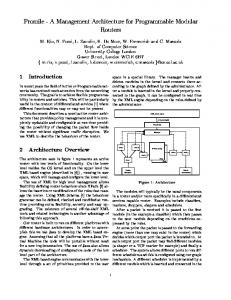
0 Figure 1: Simple string search engine for “ABC”: Since the input sub-pattern is “ABD”, the comparator detects no match. in figure 3 the dynamic pattern search engine work together with static header detector to provide more accurate results.
3.1 Compact Pattern Search Tree Directly applying the above concept gives a simple design with regular structure. On the other hand, it is a large design with many redundant substructures. We next begin to develop a design that is more area efficient.
3.1.1 Reusing Comparators Each byte comparator is constructed using 8-to-1 bit decoders. Since all the comparators use the same data input pins, there are many duplicate decoders. Therefore, we can retain one decoder output for all the duplicate decoders instead of distributing the same logic at every instance of the pipelined chains [4, 6]. For example, figure 4 shows that the output of the “B” decoder in the first pipeline stage can be reused for two other decoders in the second pipeline stage. By eliminating all the duplicate logic, the example design only needs a total of eight decoders. Thus, the total logic requirement for the example is reduced to 25 percent of the original design.
The basic concept of our deep packet filter is a direct byte to byte comparison done in parallel hardware. As shown in figure 1, the reconfigurable logic gates are configured into chain of 8 to 1 bit decoder to detect stream of target patterns at every cycle.
System with a large set of patterns maps all or most combinations of 8-bits. Therefore, 8-to-256 bit decoder can be placed at the header of each byte alignment of the search engine to provide 1-bit comparison result for incoming sequences of bytes [4, 6].
Using the same concept, the processing unit is scaled by widening the bus and adding duplicate inspection modules for different byte alignments. The system can achieve higher bandwidth using parallel sets of sub-pattern comparator in place of the 1-byte comparators in figure 1 [5, 4]. Figure 2 illustrates the inspection modules with four times the bandwidth of the single byte datapath.
In addition to 1-byte comparison, a design with wider datapath requires inspection of the sub-patterns at different alignments of the bus. As shown in figure 2, a 4-byte datapath contains four multiple byte comparators at each pipeline stages. Since all sub-pattern detectors are connected in parallel, there may be multiple comparators that check for the same sequence. As we eliminated of all the duplicate 1-byte decoders, the sub-pattern comparators can also be trimmed.
These modules are connected in parallel, to compare incoming data with all the target patterns at every cycle. Therefore, performance of the filter is only dependent on the bus width and the maximum clock rate of the design. As shown
As example of the sub-pattern combining process is shown in figure 5. There are 15 sub-pattern comparators that are used to construct the detectors for the patterns “BABAB”
A B C D 0
1
0
E
0
e
0
A B C 0
A B 0
1
1
D E
C D E
1
1
e
0
0
0
e
0
A
E A B C
MAC RULE 1 Match
Control Unit 32bit Reg.
Prot
0
IP Addr
0
Port Num
1 B C D E
0
e
...
D E A A
Match
AND Enbl Content Pattern Match RULE 2 ... RULE n
0
0
Malicious Packet Flag OR
Err
Pipelined 32 bit Data Stream
Figure 3: Parallel deep packet filter Figure 2: Parallel string search engine for “ABCDE”: “ABC” was matched on the previous cycle, enabling the registers to allow signal from “DE” comparator to latch; on following clock cycle, Match signal would indicate a match. and “ABAB”. From inspection, we find that comparators for sub-patterns “ABAB”, “BAB”, “AB”, and “B” can be reused. [4]. Every target pattern is broken into a set of byte segments of lengths less than the width of the datapath. Then a set of unique segments can be extracted from the original set. Each of the unique segments are then implemented as a single comparator that simply ANDs four output bits from the 8-to-256 bit decoder. The outputs from these subpattern comparators are forwarded to all the stages of the modules that use them.
3.1.2 Forming a Keyword Tree Aho and Corasick’s keyword tree [1] is used in many efficient software pattern search algorithms, including the Snort IDS [7]. We borrow the same concept to reduce the amount of hardware required to construct the pipelined pattern search engine. As shown in figure 6, keyword tree is a way to store set of patterns into an optimized tree of common keywords. The conversion not only reduces the amount of required storage, but it also narrows the number of potential patterns as the program traverses down the tree. Accordingly, the search pattern set can be restructured into keyword trees. Constructing the trees for our purpose requires that the length of each keyword be in multiples of the datapath width. Once the keyword tree is generated, it is converted into the pattern search tree with same function as parallel units with less logic.
3.2 Signature Index The inspection module for each pattern produces a 1-bit output to indicate a match at that clock cycle. It maybe sufficient in some applications to simply indicate a match,
4Byte Input
8 8 8 8
B A B B A B A B A B
A B A A B A B A B A
B A B B A B
Rule for “BABAB”
Rule for “ABAB”
Figure 4: Reusing common 8-bit comparators: All the duplicate comparators in the same alignment are combined. with identification accomplished in software. However, it is often desirable to produce a corresponding signature index number. A small index encoder module can be written in VHDL as a chain of CASE statement. However, an encoder with thousands of input does not make such construction feasible due to poor translation of most synthesis tools. In a naive implementation of an encoder for a large set of rules, the index encoder is almost always the critical path for of the entire system. Consequently, we have investigated more efficient designs.
3.2.1 Simple Index Encoding For the purpose of generating a compact hardware, we assume only one input pin will be asserted at any clock edge. With this assumption, our address encoder can be built using the combinations of outputs from the binary tree of OR gates as shown in figure 7. Based on natural characteristic of the binary tree, we deter-
Same Substrings
4Byte Input
8 8 8 8
M
B A B B A B A B A B
A B A A B A B A B A
B A B A B A B B A B
B A B B A B
Rule for “BABAB”
Rule for “ABAB”
B C
E X I S T E D G E
3 7
2 6
5
15 14 13 12 11 10 9
1 4
0
3 8
7
2 6
5
1 4
3
0 2
1
0
some cases limited output pin count may make it infeasible to have multiple index output. Therefore, in such case, it maybe desirable to designate a priority to the pattern index.
The problem of simultaneous pattern detection is only seen when two or more input pins are asserted at the same time. When multiple input pins are asserted, our encoder applies a bit-wise OR to all the index numbers. Therefore, at the output pin, we will see the combined output of two or more indices which may not give any indication of detected indices. By pre-processing and reassigning the index orders, one can effectively give priority of one pattern over another.
M P L E C T
I S T D G E Figure 6: An example of Aho and Corasick’s Keyword Tree: 6 bytes are optimized away. mine that each index bit is on if any of the odd nodes on the corresponding level of the tree is asserted. For example, a four bit index encoder for a 15-input encoder is written as equations 1 through 4. Index3 = a1
(1)
Index2 = b1 + b3
(2)
Index1 = c1 + c3 + c5 + c7
(3)
Index0 = d1 + d3 + d5 + d7 + d9 + d11 + d13 + d15
0
We have developed two methods for assigning index priorities. The first method uses software pre-processing to assign priority numbers to the patterns. The other method directly modifies the hardware to implement index priority.
E X A C T
A
1
Figure 7: A binary OR tree - logic equations indices are derived using the OR tree. All the unused gates are trimmer off to save hardware resource.
E X A M P L E
X
A
D
Figure 5: Reusing Common Substrings: All the matching substrings with same alignment are combined.
E
0
(4)
A static pattern search unit working with dynamic search unit would most likely cause only one of the input pins to be asserted at any cycle. However, there is still a possibility that a search engine will detect more than one pattern at one time instance. In this situation, the previously described index encoder may not be sufficient. One solution to the conflict is to divide the set into multiple sets; each subsets containing non-overlapping patterns. Then each subset pattern search unit can have its own index encoder. In
For all the patterns that can assert encoder inputs at the same time, one can assign index numbers to satisfy equation 5; which applies bit-wise OR to all the indices where In is an index number with higher value of n indicating the higher priority. In |In−1 |...|I0 = In
(5)
Once all the indices are assigned for the overlapping patterns according to the desired priorities, the indices can be assigned to the rest of the patterns. In this method, there is a limitation place on the size of prioritized pattern set. The maximum number of indices for each set is equal to the number of index output pins. There may be several independent sets of overlapping patterns in a realistic configurations, but their number of simultaneously overlapping patterns are usually less than four. Therefore, for most sets, this technique is sufficient. The advantage of using this method is that no additional gates are needed. For situations where strict priorities are need, we present a hardware priority index encoder. With additional gates, each pattern can have an index priority. We design a priority index encoder with higher index signifies higher priority. According to the binary OR tree, the most significant index bit of is “1” if any of the D nodes under A1 node is asserted. Since the higher numbered D nodes have the priority over
the lower, the output of A0 node need not be considered. Therefore, the most significant bit value is assigned as the output of A1 . For the next address bit, we consider branches with nodes that are immediate children of A1 and A0 . We can deduce that the second index bit is “1” if the output of B3 is asserted. But this time, we also find that the index bit is “1” if the output of B3 is “1” while none of the D nodes under A1 is asserted; we only need to check that A1 is “0” to guarantee that none of its children nodes are asserted. Using such method, equations for less significant bits can be constructed. We apply this method for a 15-bit input to extract index bit equations 6 to 9. Index3 = a1
(6)
Index2 = b1 · a1 + b3
(7)
Index1 = c1 · b1 · a1 + c3 · a1 + c5 · b3 + c7
(8)
Index0 = d1 · c1 · b1 · a1 + d3 · b1 · a1 + d5 · c3 · a1 + d7 · a1 + (9) d9 · c5 · b3 + d11 · b3 + d13 · c7 + d15 With registers at the output encoded address bits, the critical path has maximum of (log n)-1 gate delays where n is the number of the input pins. Since pattern search structures are pipelined after every gate, such long chain of gates become the critical path. Each look-up-table in most FPGAs are usually paired with a D-flipflop. Therefore our design of the encoder inserts additional pipeline registers. Figure 8 shows the pipelined OR tree with most 2-two input gates replaced by 1-four input gate followed by D-flip flop. The logic for index equations are also further pipelined to maintain 1-level of gate in between pipelined registers.
Suffix
Prefix Address Read Only Match Memory Module
Data In
Suffix Pattern
Byte Alignment
Comparator
Multiplexed Pipeline
Match Bit
Pipelined Pattern
Figure 9: Block diagram of a memory based pattern search engine trated in figure 10. For multiple byte datapath, the alignment information of the matching prefix is used to realign the data for correct comparison. Unlike the 8-to-256 decoder used as a comparator, the 1byte XOR comparators needed in the design requires over eight gates. But, since only one set of comparators is used by all the patterns stored in the ROM, the average gates per byte can be much less than the full decoder implementation.
Prefix A B
C
Suffix D
...
Translated
Prefix Match Module
Address
...
Stored
Read Only Memory
D-Flip Flop
A
Stage 2
1 3
B
4.1 Pattern Selection
1
2 D-Flip Flop
Stage 1
C D
7
6
5
15 14 13 12 11 10 9
4
3 8
7
2 6
5
1 4
3
2
1
Figure 8: Highly pipelined binary OR tree - two 2 input gates are collapsed into one 4 input gates to reduce the gate count. Pipelining is applied for single gate level of critical path.
4.
Figure 10: Pattern prefix and suffix
RECONFIGURABLE ROM FILTER
We have also developed a memory based filter as shown in figure 9, that uses the decoder based filter to “pre-screen” the beginning part, which we call “prefix”, of the potential pattern before invoking complete comparison with the rest of the patterns called “suffix.” The index generated by the prefix search engine points to an address into a ROM where the suffixes are stored as illus-
In order for a given design to function correctly, one must partition the patterns and map them into the ROMs. The most important condition in partitioning the rule set is that all the prefixes in each partition must be unique. For different length prefixes, the tail end of the longer prefixes in the partition must not match the shorter prefixes. Otherwise, more than one prefix match can occur. If there are more than one prefix detection, the module can not determine which suffix to read from the ROM. Since every clock can potentially produce a valid index, suffix comparison must be done at most once per cycle. Thus, any prefixes that can produce two different alignments must be assigned to separate ROMs. For a single byte datapath, this constraint does not cause any problem, since the data is always at zero alignment. However, certain prefixes can match two different alignments in multiple datapath design. For instance, let’s assume that in the 4-byte datapath, a prefix match module was configured with a prefix “ABAB”. If the incoming data started with “ABAB,” the alignment for the prefix could be either 0 or 2. Therefore, depending on the datapath and the lengths of the prefixes, conditions must be formed to test every pattern in the set to allow only
4.3.1 Improving Memory Utilization
Consider further that in a 4-byte datapath with fixed 4-byte prefixes, all prefixes in the partition must meet the following three criteria. (1) Byte 1 of the prefix can not be equal to byte 4. (2) The substring from byte 1 to 2 cannot equal substring byte 3 to 4. (3) Substring from byte 1 to 3 cannot equal substring byte 2 to 4. Other alignment constraints are possible, but 1 and 4 byte designs are the most likely to be built.
After the patterns are partitioned into ROMs, each set may contain suffixes of varying lengths. When the set is stored in the ROM, the memory utilization tends to be low due to the fixed width of the memory; which is as wide as the longest suffix entry in the set. There are a few ways to modify the memory to improve its utilization. Since our goal is to minimize the logic resource, we present a simple modification to the memory that can greatly increase utilization.
Width K bits
4.2 Prefix Match Module
Prefix 1 Alignment
Prefix 2 Alignment
N Entries
The role of the prefix match module is to match an incoming data with a prefix of patterns configured in the datapath. For multiple byte datapath, it must also generate an alignment offset of the corresponding suffix.
Width (K+1) bits N/2 Entries
up to one index detection at each cycle.
Prefix N Alignment
OR
Addr Enc
Byte Alignment
Suffix Index
Figure 11: Prefix match module The pattern search engine of the prefix match module is equivalent to the decoder based pattern search engine presented earlier. In addition to the pattern search engine, for multiple byte datapath alignment information must be generated as shown in figure 11. Our software synthesis tool guarantees that only one prefix in a given subset will be detected at each clock cycle, it does not have to consider the priority of matching patterns as with the decoder filter.
4.3 FPGA Memory Module Since memory modules are not standardized among different FPGA manufacturers, describing a generic and efficient memory module in VHDL is difficult. Even if the generic VHDL module are created, most vendor-specific compilers usually do not effectively map them as a memory. Instead, memory modules are usually transformed into combinational logic that may waste large amount of resources. In order to most effectively use the embedded memory, a target specific VHDL generator is necessary.
(a) Sorted Suffix
(b) Higher Utilization
Figure 12: Rearranging data to increase memory utilization While experimenting with dividing the patterns, we found that the majority of sets were mid-size suffixes. Most of the sorted suffixes look similar to figure 12a. When these patterns are stored directly into the memory, nearly half of the memory is wasted. Our modification improves the utilization by filling in the empty spaces with the valid data. We begin by sorting the patterns in the set by their length. Then all the even entries are sequentially stored from the first entry of the memory to the last. Then all the odd entries are stored flipped in terms of bit sequences and stored from the last entry to the first as shown in figure 12b. This process effectively stores the odd entries into a transposed memory. Addr(m:1)
Data(k:0)
0
Physical Address
Memory addr
1 Addr(0)
0
Output(K:0)
data
(m−1:0)
1 d
DFF
Data(0:k) q
CLK
Figure 13: Increasing the memory utilization Most FPGA vendor tools have memory primitive templates that can be used to correctly configure the built-in memory. A primitive template is chosen based on the dimensions of the pattern set for the best utilization. For the pattern search application, the memory configuration with the widest data bus is the best because of the long length of the patterns. Once the template is chosen for a given pattern set, its suffixes are processed and written in to the multiple primitive modules. These modules are instantiated and connected within a top memory module to hide the distribution of the memory content over multiple modules.
In order to correctly read the rearranged memory entries, a small amount of wrapper logic is necessary. Figure 13 is a block diagram of the wrapper logic. At the address input of the memory, all the bits, except for the least significant bit (LSB), are passed to the actual memory. The LSB is used to determine whether the memory is even or odd. If the address is even, the rest of the address bits are unchanged and passed on as a physical address. Otherwise, the address bits are first inverted and then passed on to the memory. Likewise, the output of the memory is connected to a 2-to-1
multiplexor with the LSB connected to its select pin. When the LSB indicates even entry, the normal output is selected. If odd entry is called, the output with the reversed bit order would be selected. The address assignment of each suffix is very important factor in high utility of such memory architecture. Therefore, the dimensions and the constraints of the memory should be consider during the pattern partitioning process.
4.4 Suffix Comparator Once the suffix is read from the ROM, the subsequent data is pipelined and shifted to the lineup at the comparator as in figure 14. Based on the length of the longest pattern and ROM latencies, the number of pipeline stages are determined. The shifters are made with a single level of multiplexors or they are pipelined to multiple levels, depending on the width of the input bus. Since one byte datapath has only one alignment, no shifters are necessary.
Align Data
Shifter (Multiplexor)
Bit−wise Compare
Match
increases the D-flip flop usage. But since each LUT is paired with one D-flip flop, the design does not become much more complex. We also reduce the size of the decoder filter by trimming the duplicate logic using the keyword tree [1]. We increase the memory utilization by partitioning the patterns according to the available space in the memory. For our design, we use the Snort rule set from end of March 2004. There are 1,625 unique content patterns in the entire set of 2,207 rules in Snort IDS. The total number of bytes in the extract patterns is 20,800. First, we implement the pattern set using only the reconfigurable decoder architecture (sec 3). Since this design only uses discrete gates, the number of gates is larger than the memory based design. Accordingly, none of the built-in memories in FPGA are used. Depending on the application and the available FPGA devices, such design choice may be preferable. Also, none of the gates in this design have to be placed around a large, common, internal components such as block memory as in ROM based filter. Since the design has fewer FPGA CAD placement constraints, it is able to run at a slightly faster clock rate. The full decoder based design successfully placed and routed into a single Xilinx Spartan 3 - XC3S1500 device using only 16,930 LUTs. The highest clock rate for the design is 250 Mhz, making the bandwidth of our dynamic pattern filter 2.0 Gbps. Pattern Decoder Tree
Prefix Decoder Tree
Suffix Suffix Length
Index
Figure 14: Suffix comparator: the incoming data is shifted to the corresponding alignment. Then the suffix is compared against aligned pattern. In addition to suffix data, ROM must store the length of each pattern. The length is decoded at the comparator to only enable the comparators of the indicated length. Then the memory output is compared with byte aligned packet data. When the data matches the suffix, the prefix index used as memory address is forwarded as an output to identify the detected pattern.
5.
IMPLEMENTATION RESULTS
We now present our implementation of 1-byte datapath using a combination of the architectures in the previous sections. By comparing with our previous designs and other research works, we show that a 1-byte datapath with a combination of decoder trees and ROM based detector yields the smallest design with high bandwidth for use in current network security devices. There are a few key improvements we made to our current design. In order to increase the clock rate of our design, we pipeline the entire design to guarantee at most 1-level of gate delay between two pipelined registers. This modification
FF
E
Index
Index
Index
Mem Filter
Mem Filter
Mem Filter
FF
E
FF
E
Pattern ID
Figure 15: Combining Decoder Tree with Memory based Pattern Search Module. As we mentioned earlier, the patterns assigned to the same ROM must have unique prefixes. Given the fixed number of available memory modules, some patterns may not partition into any one because of the above constraint. Only way to configure such patterns is by converting them into decoder filters. Due to larger resource requirements for the generic XOR based comparators, smaller set of patterns often are more efficiently implemented as a hardware decoder. With these modifications, we generate the same pattern search design that takes advantage of the best of the both
architectures. The block diagram of this compact design is shown in figure 15. Since the prefixes for patterns stored in the memory are essentially a set of shorter patterns, they are combined with the rest of the patterns to yield an efficient keyword tree. Since large amounts of patterns are stored in the memory, the overall design requires much less gates than the decoder based filter. As a result, the full filter successfully placed and routed into a smaller Spartan 3 - XC3S400 device. The system uses total of 4,415 LUTs with a clock rate of 200 Mhz in XC3S400 device and at 237 Mhz in XC3S1000 device. The speed up in XC3S1000 device is due to higher degree of freedom in placing the components in the larger FPGA. In the instances where pattern detection rate is low, it may be sufficient to indicate a match signal without identifying the pattern. Software can do a thorough search of the database to determine which pattern was detected. For such design all the index encoder for the decoder based matcher can be replaced with tree of OR gates to reduce the amount of gates. Due to our efficient index encoder design, only 755 LUTs can be reclaimed from the first design and 65 LUTs for the memory based implementation.
6.
CONCLUSION
To summarize, we tabulate our area and performance numbers along with the most recent results from various researches in Table 1. Due to our highly pipelined datapath, our dynamic pattern search implementations with 8-bit input bus produce comparable performance as other implementations with wider input. Design
Device
Cho-MSmith Spartan3 RDL+ROM 400* Cho-MSmith Spartan3 RDL+ROM 1000 Baker-Prasanna Virtex2 USC Unary Pro100 Cho-MSmith Spartan3 Reconf-Decoder 1500 Sourdis et al. Virtex2 Predecoded CAMs 3000 Clark-Schimmel Virtex RDL based 1000 Clark-Schimmel Virtex2 RDL based 8000 FranklinVirtexE Hutchings 2000 Gokhale et al. VirtexE CAM based 1000
BW # of Total Mem Gates/ (Gbps) Bytes Gates (kb) Byte 1.60
20800 4415
162
0.21
1.90
20800 4415
162
0.21
1.79
8263
2892
0
0.35
2.00
20800 16930
0
0.81
2.68
18031 19902
0
0.97
0.80
17537 19698
0
1.10
1.86
17537 29281
0
1.70
0.40
8003 20618
0
2.58
2.18
640
24
15.19
~9722
* The least expensive and the smallest FPGA for the equivalent application.
Table 1: Area and performance comparison table [2, 17, 6, 10, 11] Since most FPGAs are equipped with significant amount of memory in addition to the logic gates, the gates per pattern byte is a useful measure of the area efficiency of such
designs. As seen in the table, our implementation is about 1.7 to 8 times more space efficient than other most recently published result with similar bandwidth. From doing further experiments, we find that scaling the design into multiple byte datapath increases the area at a rate well below the linear growth. This is due to additional hardware saving when sub-patterns are reused in multiple byte datapath. On this paper, we present a compact intrusion detection filter architecture that is suitable for inexpensive FPGAs that are available today. The filter that detects all the Snort NIDS patterns can be mapped on to a 400k FPGA device (Xilinx Spartan 3, XC3S400). Due to the fine-grain pipeline, the design is able to run at a rate of 200MHz despite the fact that nearly 99 % of available slices were used. Since the filter can identify a pattern at every cycle, its bandwidth can be sustained at 1.6 Gbps regardless of the complexity of the input stream.
7. REFERENCES
[1] A. V. Aho and M. J. Corasick. Efficient String Matching: An Aid to Bibliographic Search. In Communications of the ACM, pages 333–340. ACM Press, June 1975. [2] Z. K. Baker and V. K. Prasanna. A Methodology for Synthesis of Efficient Intrusion Detection Systems on FPGAs. In IEEE Symposium on Field-Programmable Custom Computing Machines, Napa Valley, CA, April 2004. IEEE.
[3] B. H. Bloom. Space/Time Trade-Offs in Hash Coding with Allowable Errors. In Communications of the ACM. ACM, July 1970. [4] Y. H. Cho and W. H. Mangione-Smith. Deep Packet Filter with Dedicated Logic and Read Only Memories. In IEEE Symposium on Field-Programmable Custom Computing Machines, Napa Valley, CA, April 2004. IEEE. [5] Y. H. Cho, S. Navab, and W. H. Mangione-Smith. Deep Network Packet Filter Design for Reconfigurable Devices. In 12th Conference on Field Programmable Logic and Applications, pages 452–461, Montpellier, France, September 2002. Springer-Verlag. [6] C. R. Clark and D. E. Schimmel. Scalable Parallel Pattern-Matching on High-Speed Networks. In IEEE Symposium on Field-Programmable Custom Computing Machines, Napa Valley, CA, April 2004. IEEE. [7] N. Desi. Increasing Performance in High Speed NIDS: A look at Snort’s Internals. Feb 2002. [8] S. Dharmapurikar, P. Krishnamurthy, T. Sproull, and J. Lockwood. Deep Packet Inspection using Parallel Bloom Filters. In IEEE Hot Interconnects 12, Stanford, CA, August 2003. IEEE Computer Society Press. [9] I. Dubrawsky. Firewall Evolution - Deep Packet Inspection. Infocus, July 2003.
[10] R. Franklin, D. Carver, and B. L. Hutchings. Assisting Network Intrusion Detection with Reconfigurable Hardware. In Proceedings of the IEEE Symposium on FPGA’s for Custom Computing Machines, Napa Valley, CA, April 2002. IEEE. [11] M. Gokhale, D. Dubois, A. Dubois, M. Boorman, S. Poole, and V. Hogsett. Granidt: Towards Gigabit Rate Network Intrusion Detection Technology. In 12th Conference on Field Programmable Logic and Applications, pages 404–413, Montpellier, France, September 2002. Springer-Verlag. [12] J. Lockwood, J. Moscola, M. Kulig, D. Reddick, and T. Brooks. Internet Worm and Virus Protection in Dynamically Reconfigurable Hardware. In Military and Aerospace Programmable Logic Device (MAPLD), Washington DC, September 2003. NASA Office of Logic Design. [13] J. Moscola, J. Lockwood, R. Loui, and M. Pachos. Implementation of a Content-Scanning Module for an Internet Firewall. In IEEE Symposium on Field-Programmable Custom Computing Machines, Napa Valley, CA, April 2003. IEEE. [14] M. Roesch. Snort - Lightweight Intrusion Detection for Networks. In USENIX LISA 1999 conference, http://www.snort.org/, November 1999. USENIX. [15] R. Sidhu and V. K. Prasanna. Fast Regular Expression Matching using FPGAs. In IEEE Symposium on Field-Programmable Custom Computing Machines, Napa Valley, CA, April 2001. IEEE. [16] I. Sourdis and D. Pnevmatikatos. Fast, Large-Scale String Match for a 10Gbps FPGA-based Network Intrusion Detection System. In 13th Conference on Field Programmable Logic and Applications, Lisbon, Portugal, September 2003. Springer-Verlag. [17] I. Sourdis and D. Pnevmatikatos. Pre-decoded CAMs for Efficient and High-Speed NIDS Pattern Matching. In IEEE Symposium on Field-Programmable Custom Computing Machines, Napa Valley, CA, April 2004. IEEE.